High-contrast Kerr Frequency Combs
Abstract
Kerr frequency combs with depressed harmonic at the optical pump frequency are theoretically explained and experimentally demonstrated. This result is achieved in a MgF2 photonic belt resonator having reduced density of modes in its spectrum and configured with the add-drop optical couplers. ©2016 California Institute of Technology. Government sponsorship acknowledged.
Ring resonators characterized with cubic nonlinearity produce optical frequency combs when pumped with continuous wave (cw) light of sufficient power and certain frequency kippenberg11s ; savchenkov16nano . These frequency combs, dubbed as Kerr combs, may correspond to a train of short optical pulses matsko11ol ; herr14np ; brash16s and can be as broad as an octave delhaye11prl ; okawachi11ol . In the majority of experimental studies the resonator output contains the spectral line corresponding to the pump, which is significantly stronger than all other lines of the mode-locked frequency comb. The strong cw pump produces a high output cw background, which makes it hard to observe various Kerr frequency comb regimes and the high contrast optical pulses emerging from the resonator. The frequency comb without the cw background is useful for radio frequency (RF) photonic filters and oscillators, fiber telecommunications, and spectrometers.
The large difference between the pump harmonic and the comb envelope, or small contrast of the frequency comb, occurs in part due to saturation of the resonant nonlinear process. Another reason is the geometrical mismatch between the pump light and the mode of the cavity. While the geometrical mismatch can be reduced, conventional spectrally broad Kerr frequency combs still have low nonlinear conversion efficiency bao14ol ; yi15o , so that most of the pump power is reflected from the resonator during comb generation. This happens because the laser frequency has to be tuned away from the resonator mode to support generation of the mode-locked Kerr frequency comb.
The add-drop coupler configuration, consisting of an input coupler (add port) and an output coupler (drop port), allows reducing the pump spectral line to the comb envelope level by the mode anti-crossing approachwang13oe . Usually the pump line still exceeds the harmonics of the mode-locked Kerr comb retrieved from the drop port rather significantly liang15np ; wang16arch . It is desirable to find a regime of mode-locked Kerr frequency comb generation that does not suffer from the excessive cw background. Moreover, the theory describing frequency comb generation in microresonators predicts the existence of such a regime, which has not been observed so far. One of the main results of our study is that the theory is complete and the observation of the regime is possible if a proper ring resonator is made. We show both theoretically and experimentally that it is feasible to achieve comb generation regimes for which the intracavity comb envelope exceeds the pump line, resulting in a smooth comb envelope at the drop port, where the pump reflected from the resonator is not present.
Our paper is organized as follows. We first derive the analytical formula showing the condition for the ideal intracavity comb envelope to exceed the pump line. Then we validate the analytical result numerically and present the Kerr frequency comb with a suppressed pump line experimentally generated with a MgF2 photonic belt resonator. We compare the experimental results with numerical simulations and provide an explanation of why pump harmonic suppression is not present if a large number of high order modes are supported by a resonator.
We consider a mode locked Kerr frequency comb as a train of identical temporal dissipative Kerr solitons circulating in the cavity. The envelope amplitude of the pulses can be found from the damped driven Nonlinear Shrödinger equation also known as Lugiato-Lefever equation (LLE). We introduce the dimensionless parameters for the detuning of the pump line from the frequency of the corresponding resonator mode , , and for the pump power . Here is the input power, is the nonlinear coupling constant, which is also the Kerr frequency shift per photon matsko05pra , is the mode volume, and are linear and nonlinear refraction indices, is the speed of light, is the reduced Planck’s constant, and is the coupling efficiency parameter with and corresponding to total and intrinsic resonance half-linewidths. The group velocity dispersion (GVD) is characterized by , where are the frequencies of the modes neighboring with the pumped mode. We approximate the solution of LLE as herr14np ; matsko13oe ; nozaki86
| (1) |
where is the angular coordinate in the frame that co-propagates with the field inside the ring resonator, and are soliton positions. Real and stand for cw constant background amplitude and phase. These values can be found from the algebraic stationary equation which is obtained from the LLE by setting all temporal partial derivatives to zero. The solitonic parameters can be found with the Lagrangian perturbation method herr14np ; matsko13oe as , , .
Considering that the width of the solitons is small () we find the cw component of the field:
| (2) |
The condition for generation of the high contrast comb is thus (the soliton’s pump frequency Fourier component amplitude is larger than cw background amplitude ). It is interesting, however, that apparent suppression of the pump harmonic is also possible, when , which leads to
| (3) |
Note that in this case, though the amplitude of the pump line is the same as that of soliton’s pump harmonic, the phase is different, ( instead of ). Substituting the approximated soliton parameters we arrive at the condition of the apparent pump harmonic suppression:
| (4) |
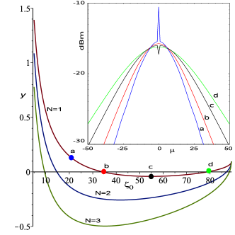
An example of graphical solution of the above equation obtained by varying the relative detuning and using , is shown in Fig.1. This also includes the simulated single-soliton Kerr comb spectra corresponding to several values of . Numerical simulations were performed using mode decomposition approach matsko05pra ; chembo10pra ; herr14prl . Exploring multiple parameters of the system we found that the carrier suppression is always possible if the pump power is high enough. Similar result was predicted theoretically for the case of a modulation instability laser coen98oc .
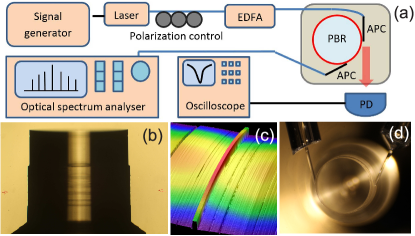
To validate the theoretical prediction we fabricated the crystalline resonator with only one mode per free spectral range (FSR) grudinin15o , and coupled this resonator in add-drop configuration wang13oe ; liang15np ; wang16arch (Fig. 2). We pumped this resonator with 1561 nm light and observed generation of Kerr frequency combs with the suppressed pump harmonic (Fig. 3).
The experimental setup is shown in Fig. (2a). Three photonic belt resonators (PBRs) are fabricated on a MgF2 polished cylinder with 2675 micrometers in diameter Fig. (2b). These resonators have typical cross sections on the order of micrometers and support dispersion engineering Fig. (2c) grudinin15o . Angle polished SMF-28 fiber couplers were used for add and drop ports. The coupling efficiency is measured as the maximum achievable dip of transmission when the distance between the coupler and the PBR is varied. This minimum transmission corresponds to critical coupling, where the resonator’s coupling loss equals the intrinsic loss. The critical coupling can be less than 100% if resonator’s output beam is not matched well to the coupler transmission. Here, all measurement were done under critical coupling setting and the transmission dip was over 60%. The drop port coupling was only enabled during comb measurements. The additional small coupler loss results in the shift towards the under-coupled regime ideality . We measured the Q factor of a specific PBR at 470 million (critically coupled) by recording its resonance curve with a Koheras 1561 nm laser and using phase modulation sidebands for frequency calibration. While single-mode by design, this resonator still supports a couple of higher order modes with poor coupling efficiency and low Q. These modes are well separated from the fundamental mode frequency in the vicinity of the pump wavelength.
We excited the frequency comb in this resonator by pumping it with 19 mW of light as measured at the output of the input angle-polished fiber coupler (“add” port). We observed the step-like multistability on the resonance curve, which is typical for soliton combs herr14np ; herr14prl ; brash16s , by tracking the power of the light reflected from the resonator (“add” port) as the laser frequency was scanned through the resonator mode.
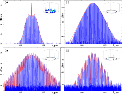
The laser frequency was first tuned to the blue slope of the resonance and we observed generation of the first pair of sidebands at 11 FSRs of the resonator (FSR GHz). The laser was then tuned closer to the mode center and a comb typical of a non-coherent state was observed (Fig. 3a) matsko13ol . We then used the frequency jump technique to excite the comb states that are typical of single and multiple soliton states (Fig. 3b-d). In this technique, the laser frequency is tuned abruptly to the expected solitonic state within the nonlinear resonance curve. As predicted by our calculations, we found that the pump harmonic was suppressed in all of these states and merged with the overall comb envelope. No tuning of experimental parameters was required. In our case the soliton states were not very stable due to temperature drift of the resonator after the frequency jumps. The slight asymmetry of the recorded spectra in addition to higher order dispersion may be also attributed to the drift of the detuning between the pump light and the corresponding resonator mode during the time needed to acquire such single spectrum (10-30 s). Further work is needed to stabilize the frequency comb completely and can be achieved by controlling the laser parameters after the frequency jumps.
There is a very good agreement between the experimental data and the results of our numerical simulations with actual experimental parameters (Fig. 3). The evaluation started at a chosen initial detuning with seeded analytical soliton train and propagated in time with slow pump frequency tuning until the boundary of soliton existence was reached. The number of calculated modes was selected to be . The case of anomalous group velocity dispersion corresponding to the experimental conditions was considered. The pump frequency detuning was adjusted until simulated comb width matched the experimental one. It was assumed that the intracavity field is sampled using the drop coupler, so the power of all harmonics of the frequency comb outside of the resonator is proportional to the intracavity power.
We found that some experimental spectra correspond to two optical pulses confined in the mode. In order to simulate the two-soliton spectra we determined the angular distance between the solitons by means of Fourier transform of the experimental spectra. Such transformation produces the autocorrelation function for the waveform brash16s . This angular distance was then used to generate the analytical expression for the soliton train, which was then used as an initial condition in the code. We found that the resulting frequency comb was not stable for smaller detunings (corresponding to longer solitons) when the experimentally determined distance was too small (Fig. 3d). The solitons were interacting, moving with respect to each other, until a stationary two-soliton cluster was formed. This observation explains the experimental difficulties with the observation of these particular frequency comb states as well as the small dissimilarity of the wings of the comb envelope observed experimentally and simulated numerically (Fig. 3d).
Let us now discuss the reasons why the pump harmonic is not always completely suppressed if one uses the add-drop port configuration and generates a broad mode-locked Kerr frequency comb. In this regime the conversion efficiency of the nonlinear process is saturated and the intracavity field at the pump frequency does not increase significantly when the pump power exceeds the oscillation threshold. Most of the pump light is reflected from the resonator. This reflection does not impact the light leaving the drop port in the add-drop coupler configuration if the resonator has a single mode family. Therefore, the carrier is expected to be suppressed in a single mode resonator. However, the insufficient pump power is one of the reasons why it does not always happen. Indeed, let us note that the condition of high contrast solitons (which follows from (2) and ) may be cast as if we take the soliton existence condition into account: herr14np ; nozaki86 . It means that the pump power needed for the suppression of the carrier harmonic is inversely proportional to of the mode (since, by definition, and ). This value is too large to be achieved in the majority of experiments involving low-Q resonators. Barring a few weakly coupled higher order low-Q modes, the resonator used in this work has the highest Q-factor of any single mode family resonators studied to date.
Dense spectrum of resonator modes is another reason why the pump harmonic suppression has not been experimentally observed in typical multimode resonators so far. There are multiple channels for the pump light to go from the add to the drop port in the case of a multimode resonator. The leakage through the higher order modes with nearly the same frequency as the pumped mode is suppressed by mode matching of the couplers. However, this suppression usually does not exceed 20 dB. Some pump light enters the high order mode families and leaves the resonator without participating in the nonlinear frequency conversion. As a result, the output power at the carrier frequency increases, in contrast with the power leaving a single mode family resonator, where such an interaction is not supported.
To illustrate this process we have measured the modal spectra of two different resonators in the linear regime. The spectrum of an 18 GHz FSR wedge-shaped resonator is shown in (Fig. 4a). The resonator supports a large number of high order modes that create a -20 dB background in the spectrum. Moreover, there is a mode that nearly overlaps with the pump mode, resulting in interference and sharp dispersion features (Fano resonances maleki04ol ; li11apl ). When Kerr frequency comb is generated with such a resonator, up to ten percent of the pump light reaches the drop port through the adjacent modes. Similarly, this explains the large pump line on top of the mode locked Kerr comb generated with multimode resonators in some studies. It is worth noting that the leakage light from the higher order modes can result in multi-path interference noises in the detected beatnote signals.
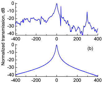
On the other hand, there is only one channel for the pump light to reach the drop port (Fig. 4b) in the single mode belt resonator grudinin15o ; winkler16oe . Observation of the intra-cavity field becomes possible, as the result.
In conclusion, we have studied generation of Kerr frequency combs in a nonlinear ring resonator pumped with cw coherent light under conditions optimized for increased comb contrast. We have shown that it is possible to observe Kerr frequency combs with suppressed pump line when the density of the optical modes in the resonator is reduced. Any increase of the mode density results in a decrease of the Kerr comb contrast due to leakage of the pump light through high-order modes not involved in the nonlinear process. The observation is important for multiple practical applications of the microresonator-based frequency combs suffering from the presence of the large cw background produced by the pump harmonic which masks optical pulses leaving the resonator and increases the noise of the comb oscillators.
The research was carried out at the Jet Propulsion Laboratory, California Institute of Technology, under a contract with the National Aeronautics and Space Administration. We thank Risaku Toda of JPL’s MDL for the optical profilometer images. M.L.G acknowledges support from the Ministry of Education and Science of the Russian Federation project RFMEFI58516X0005. V.H. acknowledges support from the Direction Générale de l’Armement (DGA). A.B.M. and L.M. acknowledge support from Defense Sciences Office of Defense Advanced Research Projects Agency under contract D16PC00158.
References
- (1) T. J. Kippenberg, R. Holzwarth, and S. A. Diddams, “Microresonator-based optical frequency combs,” Science 332, 555-559 (2011).
- (2) A. A. Savchenkov, A. B. Matsko, and L. Maleki, “On frequency combs in monolithic resonators,” Nanophotonics 5, 363-391 (2016).
- (3) A. B. Matsko, A. A. Savchenkov, W. Liang, V. S. Ilchenko, D. Seidel, and L. Maleki, “Mode-locked Kerr frequency combs,” Opt. Lett. 36, 37 (2011).
- (4) T. Herr, V. Brasch, J. D. Jost, C. Y. Wang, N. M. Kondratiev, M. L. Gorodetsky, and T. J. Kippenberg, “Temporal solitons in optical microresonators,” Nature Photon. 8, 145 (2014).
- (5) V. Brasch, M. Geiselmann, T. Herr, G. Lihachev, M . H. P. Pfeiffer, M. L. Gorodetsky, and T. J. Kippenberg, “Photonic chip-based optical frequency comb using soliton Cherenkov radiation,” Science 351, 357 (2016).
- (6) P. Del’Haye, T. Herr, E. Gavartin, M. Gorodetsky, R. Holzwarth, and T. Kippenberg, “Octave spanning tunable frequency comb from a microresonator,” Phys. Rev. Lett. 107, 063901 (2011).
- (7) Y. Okawachi, K. Saha, J. S. Levy, Y. H. Wen, M. Lipson, and A. L. Gaeta, “Octave-spanning frequency comb generation in a silicon nitride chip,” Opt. Lett. 36, 3398 (2011).
- (8) X. Yi, Q.-F. Yang, K. Y. Yang, M.-G. Suh, and K. Vahala, “Soliton frequency comb at microwave rates in a high-Q silica microresonator,” Optica 2, 1078 (2015).
- (9) C. Bao, L. Zhang, A. Matsko, Y. Yan, Z. Zhao, G. Xie, A. M. Agarwal, L. C. Kimerling, J. Michel, L. Maleki, and A. E. Willner, “Nonlinear conversion efficiency in Kerr frequency comb generation,” Opt. Lett. 39, 6126 (2014).
- (10) P.-H. Wang, Y. Xuan, L. Fan, L. T. Varghese, J. Wang, Y. Liu, X. Xue, D. E. Leaird, M. Qi, and A. M. Weiner, “Drop-port study of microresonator frequency combs: power transfer, spectra and time-domain characterization,” Opt. Express 21, 22441 (2013).
- (11) W. Liang, D. Eliyahu, V. S. Ilchenko, A. A. Savchenkov, A. B. Matsko, D. Seidel, and L. Maleki, “High spectral purity Kerr frequency comb radio frequency photonic oscillator,” Nature Communications 6, 7957 (2015).
- (12) P. H. Wang, J. A. Jaramillo-Villegas, Y. Xuan, X. Xue, C. Bao, D. E. Leaird, M. Qi, A. M. Weiner, “Intracavity characterization of micro-comb generation in the single-soliton regime,” (2016).
- (13) A. B. Matsko, A. A. Savchenkov, D. Strekalov, V. S. Ilchenko, and L. Maleki, “Optical hyperparametric oscillations in a whispering-gallery-mode resonator: Threshold and phase diffusion,” Phys. Rev. A 71, 033804 (2005).
- (14) A. B. Matsko and L. Maleki, “On timing jitter of mode locked Kerr frequency combs,” Opt. Express 21, 28862 (2013).
- (15) K. Nozaki, N. Bekki, “Low-dimensional chaos in a driven damped nonlinear shrodinger-equation,” Physica D 21, 381 (1986).
- (16) Y. K. Chembo and N. Yu, “Modal expansion approach to optical-frequency-comb generation with monolithic whispering-gallery-mode resonators,” Phys. Rev. A 82, 033801 (2010)..
- (17) T.Herr, V. Brasch, J. D. Jost, I. Mirgorodskiy, G. Lihachev, M. L. Gorodetsky, and T. J. Kippenberg, “Mode spectrum and temporal soliton formation in optical microresonators,” Phys. Rev. Lett. 113, 123901 (2014).
- (18) S. Coen, M. Haelterman, “Impedance-matched modulational instability laser for background-free pulse train generation in the THz range,” Opt. Commun. 146, 339 (1998).
- (19) I. S. Grudinin and N. Yu, “Dispersion engineering of crystalline resonators via microstructuring,” Optica 2, 221 (2015).
- (20) S. M. Spillane, T. J. Kippenberg, and K. J. Vahala, “Ideality in a fiber-taper-coupled microresonator system for application to cavity quantum electrodynamics,” Phys. Rev. Lett. 91 043902 (2003).
- (21) A. B. Matsko, W. Liang, A. A. Savchenkov, and L. Maleki, “Chaotic dynamics of frequency combs generated with continuously pumped nonlinear microresonators,” Opt. Lett. 38, 525 (2013).
- (22) L. Maleki, A. B. Matsko, A. A. Savchenkov, and V. S. Ilchenko, “Tunable delay line with interacting whispering-gallery-mode resonators,” Opt. Lett. 29, 626 (2004).
- (23) B. B. Li, Y. F. Xiao, C. L. Zou, Y. C. Liu, X. F. Jiang, Y. L. Chen, Y. Li, and Q. Gong, “Experimental observation of Fano resonance in a single whispering-gallery microresonator,” Appl. Phys. Lett. 98, 021116 (2011).
- (24) J. M. Winkler, I. S. Grudinin and N. Yu, “On the properties of single-mode optical resonators,” Opt. Express 24, 13231 (2016).