-symmetric spectral singularity and negative frequency resonance
Abstract
Vacuum consists of a bath of balanced and symmetric positive and negative frequency fluctuations. Media in relative motion or accelerated observers can break this symmetry and preferentially amplify negative frequency modes as in Quantum Cherenkov radiation and Unruh radiation. Here, we show the existence of a universal negative frequency-momentum mirror symmetry in the relativistic Lorentzian transformation for electromagnetic waves. We show the connection of our discovered symmetry to parity-time () symmetry in moving media and the resulting spectral singularity in vacuum fluctuation related effects. We prove that this spectral singularity can occur in the case of two metallic plates in relative motion interacting through positive and negative frequency plasmonic fluctuations (negative frequency resonance). Our work paves the way for understanding the role of -symmetric spectral singularities in amplifying fluctuations and motivates the search for -symmetry in novel photonic systems.
pacs:
I Introduction
Systems with -symmetric Hamiltonians have invoked interest in recent years, primarily because they enable the extension of quantum mechanical formulation to systems with complex non-Hermitian Hamiltonians Bender and Boettcher (1998). Bender et. al. discovered that Bender (2005, 2007) that for an energy eigen-spectrum to be real, the stringent condition of Hermiticity of a Hamiltonian can be replaced by a weaker -symmetry condition. A major consequence of this extension of quantum mechanical framework to non-Hermitian systems, is a new class of optical structures Rüter et al. (2010) with spatially distributed loss and gain profiles El-Ganainy et al. (2007); Makris et al. (2008); Guo et al. (2009). Such -symmetric non-Hermitian optical systems with complex dielectric profiles find promising applications in optical components ranging from couplers Principe et al. (2015) and waveguides Alaeian and Dionne (2014) to microresonators Chang et al. (2014); Hassan et al. (2016) and lasers Feng et al. (2014); Hodaei et al. (2014, 2015, 2016a, 2016b); Longhi (2010); Chong et al. (2011).
An important characteristic of the -symmetric systems is that they exhibit spectral singularities (zero-width resonance) Ahmed (2009); Mostafazadeh (2009). The -symmetric spectral singularities have been observed in a variety of systems such as, periodic finite gap systems Correa and Plyushchay (2012), confined optical potential Sinha and Roychoudhury (2013), and unidirectional singularities in Fano coupled disk resonators Ramezani et al. (2014). Recently, the -symmetric singularity in a graphene metasurface has been employed for enhanced sensing applications Chen and Jung (2016). The stabilities and instabilities in a complex potential system are also related to -symmetry Kirillov (2012). Therefore characterization of the -symmetry in a complex Hamiltonian system is important not just to enable consistent quantum mechanical formulation, but also to identify the stable and unstable regimes in photonic systems, and to predict singularities.
A moving lossy medium such as a plasma in motion is known to exhibit electromagnetic instabilities Silveirinha (2014a). These instabilities in a moving medium are caused by the Cherenkov amplification of negative energy waves Nezlin (1976) and have been recently linked to the noncontact vacuum friction Pendry (1997, 2010); Volokitin and Persson (2011); Maghrebi et al. (2013) between media at relative motion. Vacuum friction arises from quantum-fluctuation induced near-field photonic interactions Intravaia et al. (2014), and has also been studied in particles moving near surfaces Dedkov and Kyasov (2009); Intravaia et al. (2011); Pieplow and Henkel (2015); Intravaia et al. (2015) and in rotating bodies Manjavacas and de Abajo (2010); Dedkov and Kyasov (2012). The nature of vacuum friction is to oppose the relative motion, and therefore the energy spent in maintaining the relative velocities is utilized in the amplification of vacuum fluctuations, which results in the instabilities. Recently, Silveirinha Silveirinha (2014a); Lannebère and Silveirinha (2016); Silveirinha (2014b) reported that these instabilities in moving media occur because of -symmetry breaking. Recently, Guo et. al. Guo and Jacob (2014a) have shown that moving media can support singular resonances, which are manifested in giant vacuum friction and enhanced non-equilibrium heat transfer between two moving slabs Guo and Jacob (2014b). However, the origin of these singular resonances in view of the symmetries present in moving media remains unexplained.
In this paper, we reveal a -symmetric spectral singularity (zero width resonance) which occurs for bodies in relative motion. We show that this -symmetry is a consequence of a universal frequency-momentum mirror symmetry observed under the relativistic Lorentz transformations, which was surprisingly overlooked so far. We analyze the case of metallic media in relative motion and show that the spectral singularity occurs because of the perfect coupling between positive and negative frequency surface plasmon polaritons. This is fundamentally different from the case of the balance between spatially distributed gain and loss profiles known in conventional -symmetric systems. These -symmetric spectral singularities are manifested at the transition between stable regions (loss dominant regime) and region of instabilities (gain dominant regime) in the dispersion of a moving system. Our work explains the underlying cause of a giant enhancement in all phenomena related to vacuum and thermal fluctuations in moving media eg.: vacuum forces and radiative heat transfer. We show that the giant enhancement is caused by the universal phenomena of coupling between negative and positive frequencies in the near-field and therefore can be used to explain similar effects in acoustic systems Shi et al. (2016), hydrodynamic flows Nath and Mukhopadhyay (2016) and experiments on Coulomb drag Nandi et al. (2012).
II Frequency-momentum mirror symmetry
In this section, we show the existence of a frequency-momentum mirror symmetry in the Lorentz transformation laws. The time-dependent electromagnetic field solutions to Maxwell’s equations are real variables. Thus the spectral decomposition of modes necessarily consist of positive and negative frequencies which are complex conjugates of each other. For the dispersion relation in the plane, this implies that positive frequency branches are necessarily accompanied by a symmetric negative frequency branch. Under stationary conditions, the positive frequency components alone contain all the physics in the system, and therefore it generally suffices to restrict our analysis to the positive frequencies. However, both the positive and negative frequency solutions become relevant when there is a relative translatory motion in the system. This is because the Doppler shifts are velocity dependent causing the symmetry between forward/backward traveling waves and positive/negative frequencies to be broken.
The transformation of frequency () and momentum () from a stationary frame of reference to an inertial frame of reference , under the relativistic Doppler shift is governed by Kong (1975),
| (1) | |||||
| (2) |
where and is the frequency and the propagation constant (respectively), as seen in the transformed frame of reference moving with a velocity ; is the normalized velocity of translation, and . is the velocity of light in vacuum. For simplicity, we have considered translatory motion along the -axis only. The central theme of this paper is the unique relativistic transformation from positive frequencies to an equal and opposite frequency given by
| (3) |
Note that the momentum of waves is invariant to this transformation and is conserved,
| (4) |
This unique transformation is satisfied by the equation of a line
| (5) |
We call this as the frequency-mirror-symmetry condition, on which the frequency flips its sign in a transformed frame of reference while maintaining its momentum.
On similar lines, it can be shown that another special relativistic transformation exists which maps the wave momentum in the stationary to an equal and opposite momentum in the moving frame i.e.
| (6) |
This is satisfied on the line
| (7) |
Note, that in this case, the frequency is invariant to the Lorentz transformation
| (8) |
We call this as the momentum-mirror-symmetry condition.
Thus, the fundamental Lorentz transformation equations (1),(2) have universal symmetry properties in the plane such that for a given velocity , there exists,
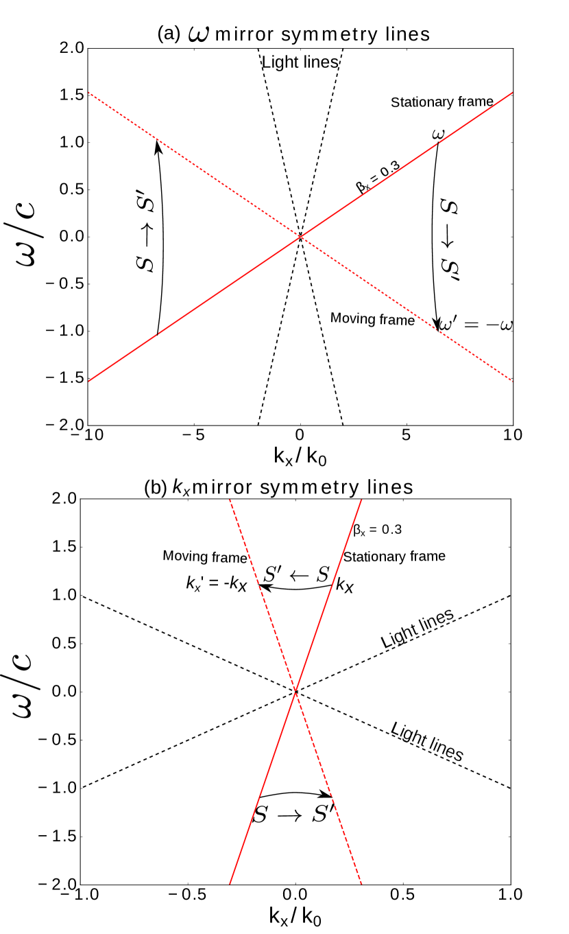
These two symmetry conditions in the plane are shown in Fig. 1, panel (a) and (b) respectively. The dashed black lines in the figure represent the light lines. In Fig. 1(a), the solid red line represents the equation (5) for , in the stationary frame of reference denoted by . The line then transforms to the dashed line in the moving frame of reference denoted by . It can be seen that a positive frequency mode satisfying equation (5) transforms to its negative frequency counterpart while the momentum is invariant, i.e. it exhibits frequency-mirror-symmetry. Similarly, Fig. 1(b) shows the transformation of a momentum-mirror symmetry line. It should be noted that while the momentum-mirror symmetry line lies inside the light line, the frequency-mirror-symmetry condition can be satisfied only outside the light line, i.e. when the phase velocity is lower than the velocity of light.
The frequency-mirror-symmetry condition with its flipped frequency and invariant momentum (shown in Fig. 1(a)) is of particular interest, because it enables the observation of the negative frequency electromagnetic response of a medium at positive frequencies. Thus, an EM mode at on the frequency-mirror-symmetry line, will be transformed to in a moving medium, and consequently its negative frequency response will be observed in the stationary frame of reference.
III Negative frequency response at positive frequencies
Our mirror-symmetry arguments are completely general and apply in the relativistic case. Here, we show a practical scenario where this symmetry is manifested. First,we provide a physical interpretation of negative frequency modes followed by the role of the universal symmetry described above. The electromagnetic properties of a metal slab in relative motion with a velocity , as observed in the stationary lab frame of reference are governed by the Lorentz transformation of constitutive relations. However at low velocities () under the First Order Lorentz transformation (FOLT) limit, the dielectric response of the slab as seen from the stationary lab frame is Kong (1975), where is the dielectric response of the metal and is the frequency as seen in its proper frame of reference. is obtained by transforming as per equation (2), which simplifies to under FOLT limit. The dielectric response as seen in the lab frame of reference is then given by
| (9) |
It can be seen that the dielectric response of a moving metal slab is not just dependent on frequency, but also on the propagation constant and the velocity of motion. As a consequence, an incident wave of frequency and propagation constant will observe a negative frequency dielectric response of the metal when,
| (10) | ||||
| (11) |
This is the Cherenkov condition at which the velocity of motion is greater than the phase velocity () of the wave Čerenkov (1937); Ginzburg (1996).
The condition of can be physically satisfied only when . This requires the momentum to be larger than the free space wavevector causing the waves to decay in vacuum. Thus the negative frequency transformation for metallic slab in motion can occur for near-field evanescent waves. We now analyze the reflection properties of such evanescent waves at the vacuum-metal interface. The origin of such evanescent waves could be quantum emitters or another stationary slab in the near-field of the moving slab. The normal component of Poynting vector () of an evanescent wave absorbed at the metal interface is proportional to the imaginary component of the reflection coefficient () Guo and Jacob (2014a).
| (12) |
Therefore the reflection coefficient of a semi-infinite Drude metal () slab sheds light on the absorption and amplification characteristics of the medium. Note that the tangential boundary conditions and hence the Snell’s reflection law at moving media interface is valid when the motion is in the plane of the interface Kong (1975) [see Appendix A].
The sign of the imaginary component of the reflection coefficient () is representative of the loss in the metal slab and it’s peak follows the dispersion curves of a surface plasmon polariton (SPP). For any lossy metal, is positive. However, this is strictly true only at positive frequencies. At negative frequencies, the dielectric response and the reflection coefficient is the complex conjugate of its respective positive frequency values ().
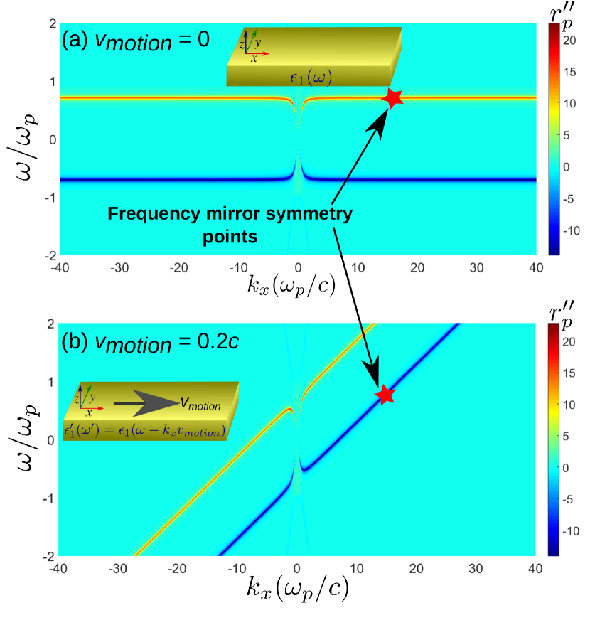
Fig. 2(a) shows the dispersion of the p-polarized plasmonic mode in the plane. It can be seen that the SPPs have positive peaks in for positive frequencies ( region), and negative peaks for negative frequencies ( region). The negative frequency region actually corresponds to the complex conjugate part of the electromagnetic field solution. The mode solutions have phase fronts which are forward propagating when and have the same sign and when they have opposite signs the mode is backward propagating. Therefore the complete representation of a forward propagating mode includes the first and third quadrant solution, while that of a backward propagating mode includes second and fourth quadrant. It should also be noted that in the stationary case, the dispersion characteristics are symmetric for the forward () and the backward propagation () as well as positive and negative frequencies.
Motion of the slab breaks the symmetry of the dispersion relation since the Lorentz transformation of frequency and momentum (or equivalently the fields) is velocity dependent. In the extreme case, when the slab is moving with velocity above the Cherenkov limit, the negative frequency mode from the fourth quadrant is dragged into the positive frequency region. Note the phase of the wave is an invariant of motion and the condition for real EM fields holds true in all reference frames. The symmetry breaking in the dispersion relation due to motion is shown in Fig. 2(b). The negative frequency mode which is dragged into the positive frequency region has negative , implying gain characteristics in the positive frequency domain. A slab moving above the Cherenkov limit has two forward propagating modes and no backward propagating mode. One of the forward propagating modes is an ordinary lossy mode (shown by red peak in ), while the other mode is amplified (growing mode shown by blue peak in ). The motion of the dielectric slab results in the violation of time reversal symmetry.
| (13) |
We would like to emphasize that the above argument is valid even at relativistic velocities, even without FOLT approximations.
Note the existence of a special frequency-mirror-symmetry when the observed response of the moving slab is the exact complex conjugate of its stationary value. This is shown by the starred point in the plane. While the dielectric response at this frequency-mirror-symmetry point is for a stationary slab, it is for the moving slab. If we now consider two identical parallel slabs (see Fig. 3), one in relative motion to the other, our analysis shows the existence of a unique velocity at which the dielectric response of the moving slab is the complex conjugate of the stationary slab. This occurs for a specific frequency and momentum wavevector dictated by two conditions - the dispersion relation of surface waves on the slab and the frequency-momentum mirror symmetry condition.
IV -symmetric resonance in a moving MIM waveguide
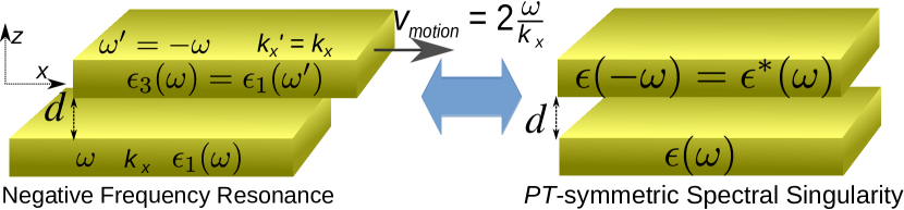
Here, we show how the relativistic negative frequency-mirror-symmetry is connected to the achievement of parity-time symmetry in a moving system. Note our work in this section is connected to the mirror-symmetry condition and not the instabilities or spontaneous -symmetry breaking in moving media Silveirinha (2014b). If we place a stationary and a moving metal slab close enough to allow evanescent wave interactions, they form a metal-insulator-metal (MIM) waveguide structure. In this structure, the stationary slab will have a dielectric response and the moving slab will exhibit dielectric response of . This is shown in Fig. 3. The separation between the slabs is . The overall dielectric distribution of the waveguide as a function of is then written as,
| (14) |
The dielectric function of the waveguide is complex in the region and . To investigate the -symmetry properties of this complex dielectric system, we write the Hamiltonian formulation for a plane wave propagation () along direction Kong (1975); Alaeian and Dionne (2014)
| (15) |
where eigenfunctions can be either or and is the eigenvalue. Assuming non-magnetic media and in the FOLT limit, can be written as
| (16) |
in which . Equation (15) will be -symmetric with real eigenvalues and unitary time-evolution if is eigenfunction of operator and,
| (17) |
From the properties of and operators, it is straightforward to show that [see Appendix B]
| (18a) | |||
| (18b) |
Combining Eq. (18a) and (18b) together, we conclude that the Hamiltonian is -symmetric if . This means that the condition of -symmetry on dielectric function, as obtained from equation (16), is the well known condition Principe et al. (2015)
| (19) |
Using equation (14) and the fact that the imaginary part of dielectric response is an odd function of frequency Landau et al. (2013), the condition for -symmetry in the moving system translates to,
| (20) |
This condition is only met when for the same value of in stationary as well as moving frame of reference, i.e. on the frequency-mirror-symmetry line of equation (5). This is a unique case where the system response is -symmetric only for a specific electromagnetic mode. Our moving slab systems does not possess time-reversal-symmetry or parity-symmetry individually for any mode. In the FOLT limit, the frequency-mirror-symmetry line simplifies to [see Appendix C],
| (21) |
We will henceforth refer to this line as the -symmetry line along which the Hamiltonian (equation (16)) is -symmetric or . Note that this condition is independent of the separation but the spectral singularity depends on the gap distance. A mode of the system on the -symmetry line will not undergo attenuation or amplification, because at this condition the loss in the stationary slab is perfectly balanced by the gain in the moving slab.
V Cherenkov amplification
We emphasize that the parametric amplification of vacuum fluctuations is well-known for the phenomenon of vacuum friction which occurs for bodies in relative motion Pendry (1997). The parametric nature arises since the evanescent wave on reflection is amplified without change in frequency or momentum. Similarly, growing electromagnetic waves and instabilities in moving plasmas and their connection to negative energy waves have been well-studied Nezlin (1976). However, the role of the frequency-momentum mirror symmetry condition in Lorentz transformations, the perfect coupling of positive and negative frequencies in the near-field and -symmetric spectral singularity has never been pointed out till date.
We note that gain in the moving system arises from Cherenkov amplification also known as the anomalous Doppler effect fundamentally different from conventional -symmetric systems. These growing waves in moving media can be seeded by vacuum fluctuations. We note that unlike the classical Cherenkov radiation where charged particles are necessary, this effect only requires the motion of neutral polarizable particles or harmonic oscillators with internal degrees of freedom. The classical dispersion relation of modes enters the classical thermal fluctuations and quantum vacuum fluctuations through the fluctuation-dissipation theorem (FDT) Levin et al. (1980).
| (22) |
where and represent the three spatial orthogonal coordinates (). is the energy of a quantum oscillator at equilibrium, given by , and is an element of the electric field Green’s tensor. We note that the FDT formalism ensures that classical mode structure affects the noise properties and effects such as Casimir forces Milton (2001); Philbin and Leonhardt (2009), near-field heat transfer Liu et al. (2015) and vacuum friction Pendry (1997).
VI -symmetric spectral singularity
In this final section, we show the spectral singularity associated with -symmetric systems is manifested in the perfect coupling of positive and negative frequency branches in moving plasmonic media. This perfect coupling occurs at a critical velocity and gap distance when negative frequency mirror symmetry is achieved for surface wave solutions. We call this a negative frequency resonance. Note that, even though -symmetry is satisfied on all points of the -symmetry line, not all on the line are valid waveguide modes. This is because a mode has to satisfy additional boundary conditions at the interfaces, which also makes the solution gap-size () dependent. To get the precise location of a mode on the -symmetry line, we compute the full dispersion curve for an MIM waveguide with one moving slab, by solving the dispersion relation,
| (23) |
in the full plane. Here, , ; is the Drude dielectric response, (or a constant) and . We consider p-polarized () wave propagation as it alone supports plasmonic modes.
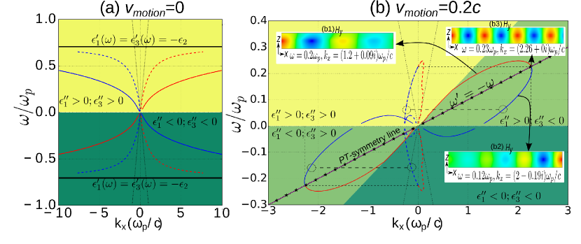
Fig. 4 contrasts the computed dispersion curves of the MIM waveguide with (a) stationary slabs and (b) one slab moving with . Background color in the plot indicates the sign of the imaginary part of the dielectric response of the two slabs ( and ). In Fig. 4a, dark yellow background represents the region where and are positive, while dark green represents the region where both the constants are negative. For a lossy medium, is positive for positive frequencies and negative for negative frequencies. Thus both slabs ( and ) are lossy in the stationary case.
When one of the slabs starts moving, its dielectric response transforms according to . Above the Cherenkov limit of , negative frequency characteristics are dragged into the positive frequency region as shown by the overlap of light green and light yellow region in Fig. 4b. In this overlap region medium-1 is lossy, while medium-3 exhibits amplifying characteristics. The -symmetry line lies in this overlap region and forms the diagonal to the rhombus formed between the region and . The condition is satisfied at all points on -symmetry line which implies the moving slab dielectric response is the complex conjugate of the stationary slab.
In Fig. 4, the real component of propagation constant () is represented by solid lines and the imaginary component () is shown by the dashed line of corresponding color. For the stationary MIM waveguide (Fig. 4a), both positive as well as negative momentum waves attenuate as they propagate in either direction, as indicated by the same sign of and for all positive frequencies ( The signs are opposite in the complex conjugate region of negative frequencies). However when one slab is moving, we notice two unique modes in first quadrant, one is a lossy mode ( and have same sign) and another is a mode exhibiting gain ( and have opposite signs). These two modes are shown by red and blue colors in Fig. 4b, respectively. The gain mode in first quadrant arises form the negative frequency component of the backward propagating mode which is dragged to the positive frequency region from the fourth quadrant. The lossy and amplified modes converge and meet on a point on -symmetric line (shown by magenta colored line with star marker). We emphasize that the propagation constant at this point of intersection is purely real, . At this point on the dispersion curve, the -symmetry is achieved and the wave propagates without any attenuation. All points on the dispersion curve above the -symmetry line are lossy, while those below exhibit gain as shown by the mode profile in inset. It can also be seen that, in contrast to the stationary case, the dispersion diagrams becomes unsymmetrical .
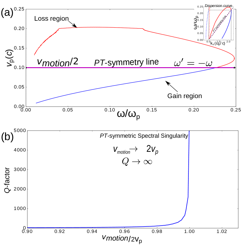
The dispersion curve and the -symmetry line intersect when the phase velocity of the mode is equal to half the slab velocity. Fig. 5(a) shows the phase velocity of points along the dispersion curve when . The corresponding dispersion curve in the first quadrant of the plane is shown in the inset. All the points on dispersion curve with phase velocity higher than are lossy, while those with lower phase velocity exhibit gain. Thus the Cherenkov limit for amplification for MIM waveguide with one moving slab, is modified to
| (24) |
The more stringent condition for amplification arises from the fact that the gain in the moving slab has to compensate for the loss in stationary slab, and therefore to achieve net gain the slab velocity has to be twice the conventional Cherenkov limit. The -symmetry condition lies at the boundary of stability (loss dominant regime) and instability (gain dominant regime).
A mode at the -symmetry condition () exhibits zero-width resonance, as depicted by the -factor of resonance in Fig. 5(b). The -factor is defined as a ratio [see Appendix D]. It can be seen that at the -symmetry condition, the -factor tends to infinity, indicating zero-width of resonance or spectral singularity. Note that non-equilibrium phenomena such as radiative heat transfer and vacuum friction will exhibit a giant enhancement when the velocity and gap size is tuned to achieve this resonance Guo and Jacob (2014b) . Our future work will focus on theoretical work beyond linear response theory to regularize the fluctuations near this spectral singularity.
VII Conclusion
In this paper, we have shown the existence of a universal frequency and momentum mirror symmetry conditions in relativistic Lorentz transformations. We have shown that frequency-mirror-symmetry is the fundamental origin of the -symmetry condition in the case of metallic slabs in relative motion. We show that the -symmetry condition is achieved only on a line which satisfy frequency-mirror-symmetry. Our work provides a clear connection between negative frequency resonances and -symmetric spectral singularity in moving media. We have considered two metallic slabs in motion to show how the spectral singularity results from perfect coupling of positive and negative frequency surface plasmon polariton branches. Our work on the coupling of negative and positive frequencies in the near-field is a universal phenomenon and can lead to similar effects being discovered in acoustic systems Shi et al. (2016), hydrodynamic flows Nath and Mukhopadhyay (2016) and experiments on Coulomb drag Nandi et al. (2012).
References
- Bender and Boettcher (1998) C. M. Bender and S. Boettcher, Physical Review Letters 80, 5243 (1998).
- Bender (2005) C. M. Bender, Contemporary physics 46, 277 (2005).
- Bender (2007) C. M. Bender, Reports on Progress in Physics 70, 947 (2007).
- Rüter et al. (2010) C. E. Rüter, K. G. Makris, R. El-Ganainy, D. N. Christodoulides, M. Segev, and D. Kip, Nature Physics 6, 192 (2010).
- El-Ganainy et al. (2007) R. El-Ganainy, K. Makris, D. Christodoulides, and Z. H. Musslimani, Optics letters 32, 2632 (2007).
- Makris et al. (2008) K. G. Makris, R. El-Ganainy, D. N. Christodoulides, and Z. H. Musslimani, Physical Review Letters 100, 103904 (2008).
- Guo et al. (2009) A. Guo, G. Salamo, D. Duchesne, R. Morandotti, M. Volatier-Ravat, V. Aimez, G. Siviloglou, and D. Christodoulides, Physical Review Letters 103, 093902 (2009).
- Principe et al. (2015) M. Principe, G. Castaldi, M. Consales, A. Cusano, and V. Galdi, Scientific reports 5 (2015).
- Alaeian and Dionne (2014) H. Alaeian and J. A. Dionne, Physical Review B 89, 075136 (2014).
- Chang et al. (2014) L. Chang, X. Jiang, S. Hua, C. Yang, J. Wen, L. Jiang, G. Li, G. Wang, and M. Xiao, Nature photonics 8, 524 (2014).
- Hassan et al. (2016) A. U. Hassan, H. Hodaei, M.-A. Miri, M. Khajavikhan, and D. N. Christodoulides, Physical Review E 93, 042219 (2016).
- Feng et al. (2014) L. Feng, Z. J. Wong, R.-M. Ma, Y. Wang, and X. Zhang, Science 346, 972 (2014).
- Hodaei et al. (2014) H. Hodaei, M.-A. Miri, M. Heinrich, D. N. Christodoulides, and M. Khajavikhan, Science 346, 975 (2014).
- Hodaei et al. (2015) H. Hodaei, M. A. Miri, A. U. Hassan, W. Hayenga, M. Heinrich, D. Christodoulides, and M. Khajavikhan, Optics letters 40, 4955 (2015).
- Hodaei et al. (2016a) H. Hodaei, M.-A. Miri, A. U. Hassan, W. E. Hayenga, M. Heinrich, D. N. Christodoulides, and M. Khajavikhan, Laser & Photonics Reviews 10, 494 (2016a).
- Hodaei et al. (2016b) H. Hodaei, A. U. Hassan, J. Ren, W. E. Hayenga, M.-A. Miri, D. N. Christodoulides, and M. Khajavikhan, IEEE Journal of Selected Topics in Quantum Electronics 22, 1 (2016b).
- Longhi (2010) S. Longhi, Physical Review A 82, 031801 (2010).
- Chong et al. (2011) Y. Chong, L. Ge, and A. D. Stone, Physical Review Letters 106, 093902 (2011).
- Ahmed (2009) Z. Ahmed, “Zero width resonance (spectral singularity) in a complex pt-symmetric potential,” (2009).
- Mostafazadeh (2009) A. Mostafazadeh, Physical Review Letters 102, 220402 (2009).
- Correa and Plyushchay (2012) F. Correa and M. S. Plyushchay, Physical Review D 86, 085028 (2012).
- Sinha and Roychoudhury (2013) A. Sinha and R. Roychoudhury, Journal of Mathematical Physics 54, 112106 (2013).
- Ramezani et al. (2014) H. Ramezani, H.-K. Li, Y. Wang, and X. Zhang, Physical review letters 113, 263905 (2014).
- Chen and Jung (2016) P.-Y. Chen and J. Jung, Physical Review Applied 5, 064018 (2016).
- Kirillov (2012) O. N. Kirillov, Physics Letters A 376, 1244 (2012).
- Silveirinha (2014a) M. G. Silveirinha, Physical Review X 4, 031013 (2014a).
- Nezlin (1976) M. V. Nezlin, Physics-Uspekhi 19, 946 (1976).
- Pendry (1997) J. Pendry, Journal of Physics: Condensed Matter 9, 10301 (1997).
- Pendry (2010) J. Pendry, New Journal of Physics 12, 033028 (2010).
- Volokitin and Persson (2011) A. Volokitin and B. Persson, Physical review letters 106, 094502 (2011).
- Maghrebi et al. (2013) M. F. Maghrebi, R. Golestanian, and M. Kardar, Phys. Rev. A 88, 042509 (2013).
- Intravaia et al. (2014) F. Intravaia, R. Behunin, and D. Dalvit, Physical Review A 89, 050101 (2014).
- Dedkov and Kyasov (2009) G. Dedkov and A. Kyasov, Physics of the Solid State 51, 1 (2009).
- Intravaia et al. (2011) F. Intravaia, C. Henkel, and M. Antezza, in Casimir Physics (Springer, 2011) pp. 345–391.
- Pieplow and Henkel (2015) G. Pieplow and C. Henkel, Journal of Physics: Condensed Matter 27, 214001 (2015).
- Intravaia et al. (2015) F. Intravaia, V. E. Mkrtchian, S. Y. Buhmann, S. Scheel, D. A. Dalvit, and C. Henkel, Journal of Physics: Condensed Matter 27, 214020 (2015).
- Manjavacas and de Abajo (2010) A. Manjavacas and F. G. de Abajo, Physical review letters 105, 113601 (2010).
- Dedkov and Kyasov (2012) G. Dedkov and A. Kyasov, EPL (Europhysics Letters) 99, 64002 (2012).
- Lannebère and Silveirinha (2016) S. Lannebère and M. G. Silveirinha, Phys. Rev. A 94, 033810 (2016).
- Silveirinha (2014b) M. G. Silveirinha, Physical Review A 90, 013842 (2014b).
- Guo and Jacob (2014a) Y. Guo and Z. Jacob, Optics express 22, 26193 (2014a).
- Guo and Jacob (2014b) Y. Guo and Z. Jacob, Journal of Optics 16, 114023 (2014b).
- Shi et al. (2016) C. Shi, M. Dubois, Y. Chen, L. Cheng, H. Ramezani, Y. Wang, and X. Zhang, Nature communications 7 (2016).
- Nath and Mukhopadhyay (2016) S. K. Nath and B. Mukhopadhyay, “A pure hydrodynamic instability in shear flows and its application to astrophysical accretion disks,” (2016).
- Nandi et al. (2012) D. Nandi, A. Finck, J. Eisenstein, L. Pfeiffer, and K. West, Nature 488, 481 (2012).
- Kong (1975) J. A. Kong, New York, Wiley-Interscience, 1975. 348 p. 1 (1975).
- Čerenkov (1937) P. Čerenkov, Physical Review 52, 378 (1937).
- Ginzburg (1996) V. L. Ginzburg, Physics-Uspekhi 39, 973 (1996).
- Landau et al. (2013) L. D. Landau, J. Bell, M. Kearsley, L. Pitaevskii, E. Lifshitz, and J. Sykes, Electrodynamics of continuous media, Vol. 8 (elsevier, 2013).
- Levin et al. (1980) M. Levin, V. Polevoi, and S. Rytov, Soviet Journal of Experimental and Theoretical Physics 52, 1054 (1980).
- Milton (2001) K. A. Milton, The Casimir effect: physical manifestations of zero-point energy (World Scientific, 2001).
- Philbin and Leonhardt (2009) T. Philbin and U. Leonhardt, “Casimir-lifshitz force between moving plates at different temperatures,” (2009).
- Liu et al. (2015) X. Liu, B. Zhao, and Z. M. Zhang, Physical Review A 91, 062510 (2015).
Appendix A Boundary conditions in moving media interface
The generalized boundary conditions at moving media interface are derived in A. J. Kong’s book Kong (1975). For completeness, we restate these conditions and show that they simplify to stationary boundary conditions in our configuration.
At moving interface the electric and magnetic boundary conditions are not decoupled Kong (1975)
| (25) | ||||
| (26) |
where is the normal to the interface. In our case the is along the interface with . Therefore the coupled terms with have zero contribution and the boundary conditions simplify to,
| (27) | ||||
| (28) |
The boundary conditions on and derived from the divergence equations remain unaltered for moving media. Therefore the Snell’s law is valid when the motion is in the plane of the interface. The reflection properties can then be computed by Lorentz transforming the material properties of moving medium to stationary frame of reference and applying the boundary conditions for stationary interface. Alternatively, the same reflection properties can be obtained by solving the boundary conditions in the proper frame of reference of the moving medium followed by Lorentz transformation of the solution to stationary frame of reference.
Appendix B Parity and Time reversal operation
Parity reversal operation performs on the system. Therefore acting on the Hamiltonian of equation (16) gives,
| (29) | ||||
| (30) | ||||
| (31) |
The time reversal operator is defined to reverse the direction of time, by performing and on the system. Therefore acting on the Hamiltonian of equation (16) gives,
| (32) | ||||
| (33) | ||||
| (34) |
Appendix C Frequency-mirror-symmetry in First Order Lorentz Transform (FOLT) limit
The frequency-mirror-symmetry line for a given is,
| (35) |
Substituting the value , we get
| (36) |
Using the binomial expansion,
| (37) |
Appendix D Q-factor of a propagating wave resonance
The line width of resonance in a system is characterized by its -factor, defined as,
| (39) |
The line width is inversely proportional to value and there is singularity in the spectrum when .
The average stored energy in the system for time harmonic fields propagating in direction is,
| (40) |
The electric and magnetic fields of a mode in one-dimensional propagation can be written as,
| (41) | |||
| (42) |
where the complex propagation constant . From (40), (41) and (42), the average stored energy in the mode is,
| (43) |
Average power dissipated by the mode as it propagates a distance in time is,
| (44) |
| (45) |
Since a phase front () travels distance in time , we have
| (46) |
From (43), (45) and (46), the average power dissipated is given by,
| (47) |
From (47) and (39) we get the -factor of the propagating mode as,
| (48) |