Magnetoplasmon spectrum for realistic off-plane structure of dissipative 2D system
Abstract
The rigorous analysis of textbook result(Chiu and Quinn, 1974) gives unexpectedly the dramatic change of magnetoplasmon spectrum taking into account both the arbitrary dissipation and asymmetric off-plane structure of 2D system. For given wave vector the dissipation enhancement leads to decrease(increase) of magnetoplasmon frequency at low(high) magnetic field. At certain range of disorder the purely relaxational mode appears in magnetoplasmon spectrum. In strong magnetic fields the magnetoplasmon frequency falls to cyclotron resonance line even in presence of finite dissipation. The recent observation of 2D magnetoplasmon spectrum is consistent with our findings.
pacs:
73.20.Mf, 71.36.+cI Introduction
Plasma oscillations in two-dimensional electron gas(2DEG) were first predicted in the middle 60th Stern67 ,Chaplik72 ,Chiu74 and, then observed experimentally in liquid helium system Grimes76 and silicon inversion layers Allen77 ,Theis78 . The observation Kukushkin03 of the magnetoplasmon spectrum reported to be affected by retardation effectsChiu74 recommences the interest to the above problem. It was argued that in large-mesa 2D systems the role of edges becomes less significant, therefore the observed MP features can be accountedCheremisin04 within conventional theoryChiu74 for unbounded 2DEG. However, the simple model of the effective dielectric function fails to account for a peculiar behavior of the magnetoplasmon spectrum. In present paper we provide the rigorous analysis of the magnetoplasmon spectrum taking into account both the realistic off-plane asymmetry and, moreover, arbitrary dissipation of 2DEG. Our results are in a good agrement with experimental findingsKukushkin03 .
II 2D plasmon dispersion law influenced by dissipation and dielectric permittivity mismatch
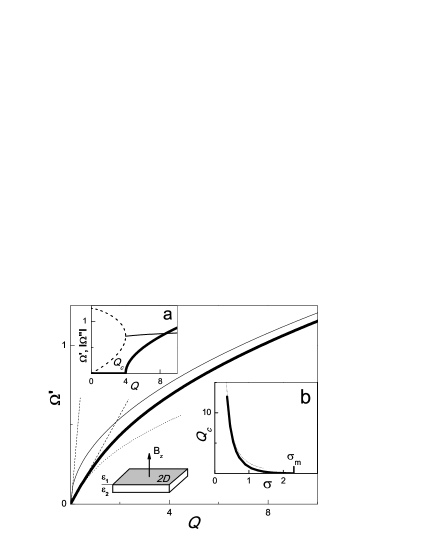
Let us assume 2DEG in x-y plane(see Fig.1, inset) embedded into the dielectric media with the permittivities and of 1,2-halfspace respectively. In perpendicular magnetic field, , the complete set of Maxwell equations for in-plane components of the electrodynamic potentials yields Falko89
| (1) | |||
where is the d’Alambert operator. In presence of the magnetic field the conductivity tensor contains the longitudinal and transverse components.
Assuming the magnetoplasmon propagated in 2DEG, and, then separating the longitudinal and the transverse in-plane components of the vector potentialFalko89 , the magnetoplasmon dispersion relation yields:
| (2) |
where denotes the inverse penetration length of electromagnetic fields into 1(2)-halfspace respectively. Note that Eq.(2) was first derived by Chiu and QuinnChiu74 . Until now, Eq.(2) was analyzed in shortcut form for off-plane symmetric 2DEG sample.
Let us specify the components of the conductivity tensor embedded into Eq.(2). Following conventional Drude formalism one can represent them as it follows
| (3) |
where is the Drude conductivity at , is the density, is the effective mass, and is the momentum relaxation time. Then, for actual problem of magnetoplasmon spectrum we use the notations made of use in Ref.Cheremisin04 . Namely, we specify the dimensionless frequency and the cyclotron frequency scaled by the dimensional unit . In addition, we use the auxiliary quantity , where the dimensionless dissipation parameter is known to be a measure of 2DEG charge relaxation dynamics in presence of retardation effectsDyakonov87 ; Govorov89 .
In absence of the magnetic field, i.e. when , Eq.(2) decouples. The left(right)-hand term in square brackets defines the dispersion law for longitudinal (transverse) plasmon respectively. The transverse mode is purely relaxationalFalko89 . Hence, our primary interest concerns the dispersion law
| (4) |
for longitudinal mode which could demonstrate the weakly damped or purely relaxational behavior dependent on dissipation strength. Here, is the dimensionless inverse penetration length, is the dimensionless wave vector.
We emphasize that the plasmon dispersion law specified by Eq.(4) is affected by the dielectric mismatch . To confirm this, we solve numerically Eq.(4) for typical GaAs-based 2DEGKukushkin03 which exhibits strong asymmetry, i.e. , . Let us first consider the dissipationless carriers case, when . The result is represented by the bold line in Fig.1, main panel. At high values of the wave vector the retardation effects can be ignored. The plasmon spectrum(see thin line in Fig.1, main panel) obeys the familiar square-root dispersion relationship with the average permittivity embedded. This intuitive result is known in literature as ”effective dielectric function approach” and claimed to be universal. We argue, however, that in the opposite low- case the average permittivity scenario fails to account the plasmon spectrum. Indeed, at the retardation effects becomes of the primary importance. Consequently, the plasmon dispersion curve in Fig.1 is located well below the lowest light dispersion asymptote associated with GaAs bulk of actual 2D structure. We argue that the common use of the ”effective dielectric function approach” is well justified for high- part of the plasmon spectrum only. In opposite low- case the retardation effects become highly important, therefore the problem of electromagnetic fields in the vicinity of 2DEG plane needs to be solved exactly.
We now examine the plasmon spectrum for real case of dissipative 2D system. At fixed disorder strength the solution of Eq.(4) gives of the complex frequency . The plasmon is damped when . We verify that for arbitrary dissipation the plasmon electromagnetic fields are indeed localized within 2D plane since .
In Fig.1,a we plot both the real and imaginary part of the longitudinal plasmon frequency vs wave vector for certain value of the dissipation strength. The evidence shows that the real component of the frequency becomes positive when , where is a critical wave vector which, in turn, can be represented as a function of and . For actual GaAs-based 2DEG we find numerically the critical diagram shown in Fig.1,b. The part of the diagram above the bold line corresponds to plasmon excitations, i.e. when . Note that for certain wave vector the graphic solution of the equation defines a critical value of dissipation, , above which the plasmon excitations exist. To confirm this finding we solve Eq.(4) and, then plot in Fig.2c,d both the real and imaginary part of the longitudinal plasmon frequency vs disorder parameter assuming fixed wave vector . We find that the longitudinal plasmon exists when . For stronger disorder the only relaxational mode exists. Substituting into Eq.(4) one can easily obtain the longitudinal plasmon damping shown by dashed line in Fig.2d. Similarly, we add in Fig.2d the transverse plasmon damping which follows from the right-hand square brackets term in Eq.(2). We conclude that for high disorder case there exists a three different relaxational modes displayed, for example, by open symbols in Fig.2d.
Remarkably, the critical diagram in Fig.1,b can be found analytically within high- non-retarded limit. Indeed, with the help of Eq.(4) both the real and the imaginary parts of the complex frequency yield
| (5) |
Actually, the Eq.(5) provides the critical diagram asymptote shown by dotted line in Fig.1,b.
We emphasize that the critical diagram demonstrates vanishing at certain magnitude of the dissipation . Fortunately, the above value can be easily found within analytic approach as well. Indeed, the substitution and, moreover, into Eq.(4) gives the result . We conclude that the long-wave plasmon always exists when . Note that in particular case of symmetric 2DEG, i.e. when , our finding coincides with that reported in Ref.Falko89 . We argue also that the dimensionless disorder parameter made of use in Ref.Volkov16 for symmetric case is related to that in our notations via the relationship . As expected, the long-wave plasmon exists when in notations of Ref.Volkov16 .
III Dramatic change of the magnetoplasmon spectrum caused by off-plane dielectric asymmetry and dissipation
The up-to-date attempts to analyze the plasmon spectrum in presence of the magnetic field concern either non-dissipative Chiu74 or dissipative 2D plasmaVolkov16 . In both cases the dielectric mismatch of 2D structure was neglected. We now demonstrate that both the off-plane dielectric asymmetry and the dissipation strongly affect the magnetoplasmon spectrum. In contrast to authors of Ref.Volkov16 we intend to consider the regular experimental setup implying the changeless 2D sample geometry. Consequently, we will analyze the magnetoplasmon excitations for fixed wave vector and varied magnetic field and compare our results with existing experimental dataKukushkin03 .
Substituting the components of the conductivity tensor given by Eq.(3) into Eq.(2) the magnetoplasmon spectrum yields
| (6) |
Evidently, the zero-field dispersion law specified by Eq.(4) follows from Eq.(6) when . We argue that for fixed values of dielectric permittivities , wave vector and the dissipation strength one can solve Eq.(6) and, then find both the real and the imaginary parts of the magnetoplasmon frequency as a functions of the cyclotron one.
Let us examine first the dissipationless case when magnetoplasmon is undamped. Substitution into Eq.(6) readily gives the sought-for spectrum in the form . For actual GaAs-based 2DEG the result is shown in Fig.2a for fixed wave vector . Remarkably, the lossless magnetoplasmon excitation exhibits a certain cutoff point on the spectrum plot. Indeed, for asymmetric 2D structure in question the magnetoplasmon penetration length becomes infinitely large for 2-halfspace when . Under this condition the Eq.(6) provides the spectrum cutoff point as and respectively. Note that for symmetric 2D structure the lossless magnetoplasmon spectrum could demonstrate the saturationChiu74 ; Cheremisin04 at high magnetic fields since .
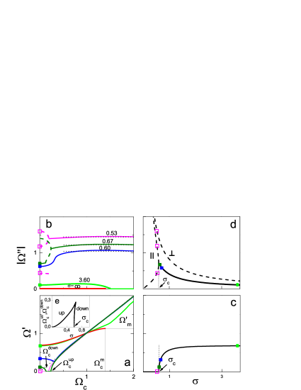
We now analyze the magnetoplasmon spectrum for fixed wave vector and, moreover, assume a finite disorder. In general, Eq.(6) can be solved numerically. The solid curves in Figs.2a,b correspond to magnetoplasmon excitations possessing the nonzero frequency. At low magnetic fields the real(imaginary) component of the complex frequency decreases(increases) under the disorder enhancement. This finding correlates with that discussed above for zero-field plasmon at (see Figs.2c,d). For given dissipation strength the zero-field plasmon frequency(damping) shown by the solid symbols in Fig.2, panel c(d) corresponds to those in Figs.2, panel a(b) respectively. In contrast, for high-disorder case the only relaxational plasma modes could appear in 2D system. As an example, the relaxational plasma modes associated with longitudinal and(or) transverse plasmon are represented by open symbols in Figs.2b,d.
We argue that the substantial drop of the lossy magnetoplasmon frequency at low magnetic fields compared to that expected for clean 2DEG can be attributed to so-called ”low-frequency mode” discussed in literatureMuravev15 ; Gusikhin14. Let us analyze in details the behavior of lossy magnetoplasmon spectrum at moderate magnetic fields. Figs.2a,b provides a strong evidence of relaxational mode appeared within a certain range of magnetic fields even for . We find numerically and, then plot in Fig.2e the dependencies vs , thus obtain the relaxational mode diagram. The area outside the triangle in Fig.2e corresponds to magnetoplasmon excitations possessing nonzero frequency. Note that for strong disorder the magnetoplasmon frequency approaches the cyclotron line which is seen in Fig.2a.
In high magnetic fields the behavior of the magnetoplasmon spectrum is striking as well. At first, the all curves plotted for different dissipation strengths demonstrate a certain crossing with cyclotron resonance line. Well above the crossing point the magnetoplasmon spectrum exhibits the change from cutoff trend owned to dissipationless case to linear in magnetic field behavior for lossy magnetoplasmon. As an example, for simplest case of lossless 2DEG we substitute into Eq.(6) and, then find the transcendental equation
| (7) |
for sought-for crossing point frequency. For GaAs 2DEG case shown in Fig.2a we obtain the crossing point at .
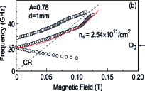
We argue that in strong magnetic fields the magnetoplasmon spectrum can exhibit(see Fig.2a) a non-monotonic behavior at moderate dissipation . To test our model, we analyze in Fig.3 the experimental dataKukushkin03 . For actual carrier density cm-2 and mesa diameter mm of GaAs 2D sample, we find the frequency c-1 and the wave vector cm-1, thus . The best fit of the lowest 2D resonator cavity mode is shown in Fig.3 for disorder strength . The later allows us to estimate the carrier mobility cm2/Vs being close to that cm2/Vs reported in experimentKukushkin03 .
Remarkably, for finite dissipation strength we are able to solve analytically Eq.(6) within high frequency limit . Indeed, one can represent the inverse penetration length as . Keeping -order terms the complex frequency yields
| (8) |
Eq.(8) is valid when whereas denotes the magnetoplasmon frequency at . Note that for symmetric 2DEG Eq.(8) coincides with Eq.(3) obtained in Ref.Volkov16 .
According to Eq.(8) at high magnetic fields the magnetoplasmon frequency follows the cyclotron resonance asymptote, while the damping depends on dissipation strength. To confirm this finding, in Fig.2 we plot the asymptotes specified by Eq.(8). Numerical data is well described by theory predictions. We emphasize also that at high magnetic fields the magnetoplasmon is always localized nearby 2D plane. Indeed, Eq.(8) allows one to find the correct inverse penetration length of the electromagnetic fields for both sides of 2D plane, i.e. .
IV Conclusions
Our analysis of textbook Eq.(2) derived in early 70-sChiu74 provides the strong doubts concerning overall use of effective dielectric function approach. We demonstrate the dramatic change of magnetoplasmon spectrum for realistic case of asymmetric off-plane structure of dissipative 2D systems. Under disorder enhancement the magnetoplasmon with a certain wave vector demonstrates the decrease (increase) of its frequency at low (high) magnetic field. At certain range of disorder the purely relaxational mode appears in magnetoplasmon spectrum. At high magnetic fields the real(imaginary) component of magnetoplasmon frequency follows the cyclotron resonance line and depends on the dissipation strength respectively. For moderate dissipation our calculations provide an evidence of non-monotonic behavior of magnetoplasmon spectrum already observed in experiment.
References
- (1) F.Stern, Phys. Rev. Lett. 18, 546, 1967
- (2) A.V.Chaplik, Sov. Phys. JETP 35, 395, 1972
- (3) K.W.Chiu and J.J.Quinn, Phys. Rev. B 9, 4724, 1974
- (4) C.C.Grimes and G.Adams, Phys. Rev. Lett. 36, 145, 1976
- (5) S.J.Allen, D.C.Tsui and R.A.Logan, Phys. Rev. Lett. 38, 98, 1977
- (6) T.N.Theis, J.P.Kotthaus and P.J.Stiles, Solid State Comm. 26, 603, 1978
- (7) I.V.Kukushkin, J.H.Smet, S.A.Mikhailov, D.V.Kulakovskii, K.von Klitzing and W.Wegscheider, Phys. Rev. Lett. 90, 156801, 2003
- (8) M.V.Cheremisin, JETP Lett. 80, 271, 2004
- (9) V.I.Falko and D.E.Khmel’nitskii, Sov. Phys. JETP 68, 1150, 1989
- (10) M.I. D’yakonov and A.S. Furman, Soviet Phys. JETP 65, 574, 1987
- (11) A.0. Govorov and A.V. Chaplik, Sov. Phys. JETP 68, 1143, 1989
- (12) V.A.Volkov and A.A.Zabolotnykh, Phys.Rev.B 94, 165408, 2016
- (13) V.M. Muravev, P.A. Gusikhin, I.V. Andreev and I.V. Kukushkin, Phys.Rev.Lett. 114, 106805, 2015.
- (14) P.A. Gusikhin, V.M. Muravev and I.V. Kukushkin, JETP Lett., Vol. 100 648 2014.