Neutron induced strike: On the likelihood of multiple bit-flips in logic circuits
Abstract
High energy particles from cosmic rays or packaging materials can generate a glitch or a current transient (single event transient or SET) in a logic circuit. This SET can eventually get captured in a register resulting in a flip of the register content, which is known as soft error or single-event upset (SEU). A soft error is typically modeled as a probabilistic single bit-flip model. In developing such abstract fault models, an important issue to consider is the likelihood of multiple bit errors caused by particle strikes. The fact that an SET causes multiple flips is noted in the literature. We perform a characterization study of the impact of an SET on a logic circuit to quantify the extent to which an SET can cause multiple bit flips. We use post-layout circuit simulations and Monte Carlo sampling scheme to get accurate bit-flip statistics. We perform our simulations on ISCAS’85, ISCAS’89 and ITC’99 benchmarks in 180nm and 65nm technologies. We find that a substantial fraction of SEU outcomes had multiple register flips. We futher analyse the individual contributions of the strike on a register and the strike on a logic gate, to multiple flips. We find that, amongst the erroneous outcomes, the probability of multiple bit-flips for ‘gate-strike’ cases was substantial and went up to 50%, where as those for ‘register-strike’ cases was just about 2%. This implies that, in principle, we can eliminate the flips due to register strikes using hardened flip-flop designs. However, in such designs, out of the remaining flips which will be due to gate strikes, a large fraction is likely to be multiple flips.
Index Terms:
soft error, gate strike, multiple bit flips, fault model, logic circuitsI Introduction
Soft errors are known to have a significant impact on circuit reliability. High energy particles from either cosmic rays or packaging materials are the major contributors towards soft errors. When such particles strike a semiconductor substrate, they generate charge which in turn results in a glitch or a transient current in a circuit. Such a glitch is called the single event transient (SET). The SET can occur on a register or on a logic gate and can propagate to eventually get captured in a register, altering the stored bit (). Such an error is known as a single event upset (SEU) or soft error. The cosmic rays interact with earth’s atmosphere creating secondary particles, mainly neutrons, protons, muons and pions, as they penetrate down to the sea level. The energy or flux of these particles increases at a rate of 5x per 5000 feet, reaching a maximum intensity at about 12-15 km from sea level [1, 2]. Thus, the errors caused due to these particles were of specific interest in satellite, aircraft and space applications. For example, in-flight measurements reveal an upset rate of approximately 5x10⁻³ upsets per hour per memory device [3].
Several studies were then conducted by IBM and were also summarized by Boeing Defense and Space group, which reveal that a significant amount of neutron flux is found even at sea level [1, 4]. The average low energy neutron flux (around 10MeV) at sea level is reported to be nearly 100000 neutrons/sq.cm per year [1]. They report that thousands of upsets happen every year at the ground level, which are mainly recorded by computer systems having error detection and correction logs. For instance, the average error rate in memories observed in several computers were reported to be nearly 1.5e-12 upsets/bit-hr and most of the upsets are reported to be due to atmospheric neutrons [4]. Thus, SEUs caused due to neutrons gained significant importance. Most early studies focused on SEUs only in memories. SEUs in logic circuits were not considered because such circuits exhibit inherent masking phenomena, which prevented the SETs from getting captured in a register/flip-flop. However, as technology scales, the impact of masking phenomena tends to reduce [5, 6, 7, 8] and it is important to study SEUs in logic circuits.
At the architectural level, soft errors are commonly modeled by a probabilistic single bit-flip fault model [9, 10, 11, 12]. In developing such abstract fault models, an important issue to consider is the likelihood of multiple bit errors caused by particle strikes. This likelihood has been studied to a great extent in memories, but has not been understood to the same extent in logic circuits. This model has been challenged in [13, 14, 15, 16], which report that multiple bit flips do occur in logic circuits. However, the state-of-art fault model continues to be a single bit-flip, single cycle model for soft error in logic circuits. Reliability estimates (such as mean time to failure/MTTF) and reliability enhancement techniques (such as error correction codes etc) are also based on the assumption that a single bit flip occurs due to a particle strike. However, in reality, if multiple errors occur, these MTTF estimates are likely to be optimistic and the error correction methods are likely to be insufficient. Most of the existing techniques that estimate soft error rate (SER) use approximate modeling techniques to arrive at these conclusions which reduces the accuracy of their results [17, 18, 19, 20, 21]. Therefore it is essential that our estimation technique be as accurate as possible, in order to increase the confidence in the conclusions on the multiple bit flip probability in logic circuits. So, we perform a detailed characterization of the impact of an SET using post-layout circuit (SPICE) simulations and Monte Carlo sampling scheme in order to get accurate bit-flip statistics. Our goal is to quantify the extent to which the single bit-flip fault model is accurate.
We performed a basic characterization to this extent in an earlier work [22]. We evaluate the bit-flip statistics by comparing the SET- induced circuit simulation with a fault-free register-transfer-level (RTL) reference simulation. In our simulations, we assume that an SET affects a single transistor [23, 24]. We run our experiments on the ISCAS’85, ISACAS’89 and ITC’99 benchmark circuits in 180nm and 65nm technologies. We found that the impact of an SET in a circuit can be understood as a two-cycle phenomenon, that is, the SEU outcomes need to be observed across two clock cycles (the cycle which had the SET injected and the following clock cycle) in order to accurately capture the phenomenon. This leads us to the fact that there are several possible SEU outcomes. We estimated the relative probabilities of all SEU outcomes and the conditional probability of multiple flips given that there is at least one error. In other words, given that an SET propagates and causes an error in a flip-flop in either of the two clock cycles, what is the probability that it can flip multiple flip-flops? We analyse these results further and evaluate this probability separately for strikes on logic gates and strikes on registers to understand their individual contributions.
We find that, overall, up to 8% of the erroneous outcomes result in multiple bit-flips. Although this probability is low, it can a have significant impact on error-detection or correction schemes. It means that a single bit error correction scheme can go wrong in as much as 8% of the cases, and these errors will go down as silent undetected errors. The probability of multiple errors also increases as technology is scaled (based on 180nm and 65nm data). A key observation is that, amongst the erroneous outcomes, the probability of multiple bit-flips for ‘gate-strike’ cases was substantial and went up to 50%, that is, these errors are caused due to the propagation of the SET from the logic gate to the flip-flop. On the other hand, out of the erroneous outcomes, the likelihood of multiple flips for ‘register-strike’ cases was just about 2%. This implies that, if we were to do hardened flip-flop designs to eliminate the flips due to register strikes, then in such designs, out of the remaining flips which will be due to ‘gate strikes’, a large fraction will be multiple flips. So, although the traditional circuit designs with hardened flip-flops will solve one problem, they will uncover a different problem.
Thus, our study reveals that multiple flips are quite likely and are likely to increase with technology scaling. Reliability estimation/enhancement approaches based on the single bit-flip model are likely to be optimistic. Gate-strikes are the key contributors to multiple flips. Robust flip-flop designs may not help; we may need to look at methods such as modifying the path delays or designs such as delay-capture flip-flops to reduce the likelihood of multiple errors due to gate-strikes. Enough precautions need to be taken at the layout/circuit/system level so that the single bit-flip model can be used with a higher degree of confidence.
We organize the rest of the paper as follows. In Section II, we provide a brief introduction to the two-cycle phenomenon and describe the possible SEU outcomes in a logic circuit. We describe the experimental setup in Section III. We present our simulation results on ISCAS’85, ISCAS’89 and ITC’99 benchmarks in Section IV. In Section V, we summarize our paper.
II Two-cycle phenomenon and the possible SEU outcomes
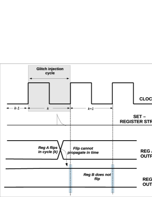
In a logic circuit, a high-energy particle can strike a logic gate or a register, resulting in an SET. We call this the ‘gate-strike’ and ‘register-strike’ respectively. We model the SET as a current injection at the drain of a transistor in a particular clock cycle ‘k’. This SET can eventually propagate and get captured in a register or a flip-flop in the same clock cycle ‘k’ or in the subsequent clock cycle ‘k+1’, depending on the time instant at which the SET occurs in clock cycle ‘k’. These two possibilities can be explained as follows. If the SET flips a register content early in the clock cycle ‘k’, it will have enough time to propagate and flip some register in clock cycle‘k+1’, as illustrated in Figure 1. However, if the SET flips a register later in the clock cycle ‘k’, the error will not have enough time to propagate and flip some other register in the subsequent clock cycle ‘k+1’, as illustrated in Figure 2. Thus, the impact of an SET, in reality, needs to be viewed across two clock cycles to accurately capture the phenomenon. We call this the ‘two-cycle phenomenon’. This time dependence of the strike is currently missing in the single bit flip, single cycle fault model.
We now classify the flips and come up with a systematic notation for the possible SEU outcomes across two clock cycles. This is shown in Figure 3. In the figure, ‘N’ stands for no-flip, ‘F’ stands for flip and ‘Fm’ stands for multiple flips. So, the illustrations in Figure 1 and 2 can be classified as ‘FF’ and ‘FN’ type of outcomes respectively as per this terminology. Thus, the occurrence of second flip depends on the time instant at which the SET occurred in the first clock cycle. Flips in the subsequent clock cycles can be understood completely based on logical propagation of the flip in the second cycle which occurs on the clock edge.

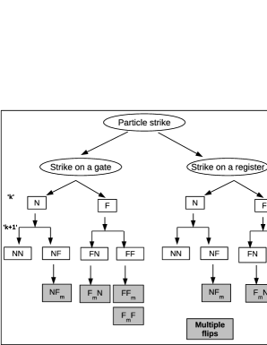
Since we are interested in evaluating the accuracy of the single bit-flip model, we focus on the likelihood of multiple register flips. The ones caused directly as a result of the SET are denoted by ‘NFm’, ‘FmF’ and ‘FmN’. The multiple flip caused due to the propagation of the previous flip is denoted by ‘FFm’, which will be anyway captured by modeling the first flip using the traditional single bit-flip model. So, the multiple flips in this case are not a direct result of the SET and we do not consider this in our experiments.
III Simulation setup
We perform our simulations on the ISCAS’85, ISCAS’89 and ITC’99 benchmark circuits in 180nm and 65nm technologies. We model the SET as a current injection at the drain of a single transistor [23, 24]. A fixed glitch is used in our experiments and we assume that the probability that an SET affects a drain is proportional to its area. We use the scaling trends presented in [25] to arrive at the glitch height and width for the technology we simulate.
Each circuit that we perform our experiment on, is described as a Verilog or VHDL netlist (RTL). The circuit is implemented to layout using synthesis and placement-route (PNR) tools. The post-layout Verilog and circuit netlist are then extracted. We simulate the post-layout Verilog netlist with a representative test-bench using the ModelSim [26] simulator and store the input/output values of all the flip-flops (registers). These are called as the reference values. From the post-layout circuit netlist, we generate ‘sample circuit simulation decks’ by picking a random clock cycle (k) for simulation, selecting a random drain (d) to inject the SET and selecting a random time instant (t) in the clock cycle to inject the SET.
The sample circuit is simulated for three clock cycles as shown in Figure 2 and the register outputs are recorded at two clock instants: ‘k’ and ‘k+1’. We use the Ngspice or Hspice circuit simulators [27] to perform our simulations. In the (k-1)th clock cycle, the input registers of the circuit netlist are initialized with the corresponding input values obtained from the RTL reference values for that clock cycle. In the kth clock cycle, we inject the SET at a random point in time (t) in the clock cycle. Inputs to the circuit change at the falling edge of the clock cycle k, so that there is sufficient setup time. We note the register outputs at the rising edges of clock cycles and . The register values from the SET injected circuit simulation are compared with the corresponding reference values from the fault-free RTL simulation. Differences between the sampled values in the circuit simulation and the reference values are recorded as bit-flips in the respective clock cycles.
We generate several sample simulation decks with different (d,k,t) values. The average number of sample circuit simulations run for each circuit was about 4000. We ran these simulations in parallel using GNU Parallel [28] on a high performance computing cluster in Centre for Development of Advanced Computing (CDAC) Pune, India, which utilizes multiple cores. The time taken to run these many simulations for each circuit was on an average about 1 to 2 hours. The key advantage of running the post-layout circuit simulations is that they capture all the masking phenomena accurately. With the availability of the high performance cluster with multi-core facility, these simulations can be run in a reasonable amount of time.
We extract the bit-flip information from each simulation and then classify these flips into one of the SEU outcomes described in Figure 3. We continue to generate the circuit samples until the standard error () is reduced to less than 10% of the value of the estimate. The probabilities obtained from this Monte Carlo sampling experiment fall within the 95% confidence interval. The experimental setup is briefly described in Algorithm 1. This entire process is automated using a set of python and perl scripts.
Input: Verilog/VHDL description of circuit
-
•
Perform Synthesis of the Verilog/VHDL description
-
•
Perform placement and route of the resulting Synthesis output
-
•
Extract the post-layout Verilog and SPICE netlists
-
•
Simulate the post-layout Verilog netlist using ModelSim for 10000 clock cycles
-
•
Store the input and output values of all flip-flops at every clock cycle
-
•
for (Number of simulations)
{
-
•
Create a sample simulation netlist from the post-layout SPICE netlist:
{
-
–
Pick a random drain d of a transistor at which the SET will be injected
-
–
Pick a random clock cycle k from the reference trace for simulation
-
–
Pick the inputs to the sample netlist from the chosen clock cycle k
-
–
Inject the SET at a random time instant t in the selected clock cycle
}
-
–
-
•
Simulate the sample SPICE netlist with parameters for 3 clock cycles
-
•
Store the output values of all flip-flops at the 2nd and 3rd clock edges
-
•
Compare the outputs from SPICE netlist with that of the Verilog netlist
-
•
Note any discrepancy in the output as a bit-flip
-
•
Evaluate the conditional probability of multiple flips given at least one error occured
-
•
Simulations are run to reach a 95% confidence interval
}
Output: Calculate the statistics of all SEU outcomes
IV Results
We perform our experiments on ISCAS’85 (c432 etc), ISCAS’89 (s344 etc) and ITC’99 (b01 etc) benchmark circuits in 180nm and 65nm technologies. Flip-flops (registers) are added to the inputs and outputs of the combinational circuits of the ISCAS’85 benchmarks. Clock frequency for each circuit is set to the maximum operable frequency of the post-layout netlist, which is determined by post-layout timing analysis. We calculate the probability of a ‘gate-strike’ and ‘register-strike’ depending on whether the SET was injected on a gate or a register. Further, we classify the bit-flips into one of the SEU outcomes described in Figure 3. Our key focus is on quantifying the extent to which multiple flips occur. We further evaluate the multiple bit flip probability contributed independently by the ‘gate-strike’ and ‘register strike’ scenarios.
IV-A Probabilities of SET outcomes
In Table I, we show the observed probabilities of all the SEU outcomes under the condition that the SET occurs at a register (‘register strike’) as shown below.
-
•
-
•
-
•
-
•
In Table II, we tabulate these SEU probabilities under the condition that the SET occurs at a logic gate ( ‘gate-strike’). A ‘-’ in the table means that the outcome did not occur. The key observations are as follows:
- •
-
•
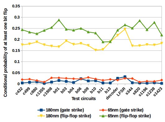
The probability indicates the probability that a flip or an error occurred. This is plotted in Figure 4. The flip probability for register-strike cases is substantially greater (nearly 10x greater) than that for the gate-strike cases. This indicates that, when an SET occurs on a register, it is more likely to cause an error, than one at a gate. Protecting the flip-flops or having robust flip-flop designs can help reduce this flip probability.
-
•
From Figure 4, we note that the flip probabilities are higher in the 65nm technology, which means that, as technology scales, the likelihood of an error increases.
-
•
In the case of strike on a register, from Table I we observe that, and are dominant as compared to . This implies that, when an SET occurs at a register, it is more likely to cause a flip in the same clock cycle (clock cycle ‘k’).
-
•
On the other hand, when an SET occurs on a logic gate, from Table II we can see that the probabilities of and are extremely small as compared to . This indicates that, when a strike occurs on a logic gate in clock cycle ‘k’, the register flip is most likely to occur due to the propagation of the SET and hence, the flip is likely to occur in the subsequent clock cycle ‘k+1’.
| Example | 180nm | 65nm | 180nm | 65nm | 180nm | 65nm | 180nm | 65nm |
|---|---|---|---|---|---|---|---|---|
| c432 | 0.824 | 0.777 | 0.003 | 0.0275 | 0.136 | 0.166 | 0.035 | 0.028 |
| c499 | 0.82 | 0.767 | 0.01 | 0.029 | 0.1 | 0.113 | 0.065 | 0.089 |
| c880 | 0.811 | 0.774 | 0.005 | 0.0225 | 0.115 | 0.135 | 0.067 | 0.067 |
| c1355 | 0.824 | 0.759 | 0.003 | 0.027 | 0.098 | 0.11 | 0.072 | 0.102 |
| c1908 | 0.83 | 0.746 | 0.006 | 0.037 | 0.112 | 0.137 | 0.05 | 0.078 |
| b01 | 0.833 | 0.712 | 0.013 | 0.038 | 0.088 | 0.116 | 0.064 | 0.133 |
| b03 | 0.806 | 0.7583 | 0.006 | 0.034 | 0.046 | 0.065 | 0.14 | 0.141 |
| b04 | 0.822 | 0.808 | 0.002 | 0.012 | 0.05 | 0.057 | 0.124 | 0.122 |
| b06 | 0.818 | 0.755 | 0.0128 | 0.024 | 0.117 | 0.156 | 0.051 | 0.063 |
| b09 | 0.827 | 0.766 | 0.006 | 0.025 | 0.024 | 0.023 | 0.141 | 0.183 |
| b10 | 0.848 | 0.771 | 0.003 | 0.029 | 0.011 | 0.022 | 0.136 | 0.177 |
| b11 | 0.845 | 0.811 | 0.006 | 0.022 | 0.025 | 0.046 | 0.121 | 0.119 |
| b13 | 0.81 | 0.81 | 0.008 | 0.026 | 0.012 | 0.013 | 0.168 | 0.146 |
| s344 | 0.829 | 0.749 | 0.011 | 0.046 | 0.136 | 0.17 | 0.024 | 0.033 |
| s820 | 0.828 | 0.715 | 0.024 | 0.022 | 0.115 | 0.159 | 0.031 | 0.1 |
| s1196 | 0.823 | 0.756 | 0.014 | 0.025 | 0.155 | 0.2 | 0.008 | 0.018 |
| s1238 | 0.825 | 0.723 | 0.007 | 0.039 | 0.157 | 0.219 | 0.01 | 0.018 |
| s1423 | 0.817 | 0.78 | 0.004 | 0.026 | 0.112 | 0.103 | 0.066 | 0.089 |
| 3:8 decoder | 0.781 | 0.732 | 0.021 | 0.041 | 0.156 | 0.154 | 0.04 | 0.072 |
| 8-bit LFSR | 0.753 | 0.734 | 0.038 | 0.034 | 0.012 | 0.01 | 0.195 | 0.22 |
| worst case standard error |
| Example | 180nm | 65nm | 180nm | 65nm | 180nm | 65nm | 180nm | 65nm |
|---|---|---|---|---|---|---|---|---|
| c432 | 0.996 | 0.98 | 0.003 | 0.019 | - | - | - | - |
| c499 | 0.993 | 0.979 | 0.004 | 0.019 | 0.001 | 0.0008 | - | - |
| c880 | 0.991 | 0.985 | 0.006 | 0.013 | 0.002 | - | - | 0.0016 |
| c1355 | 0.998 | 0.992 | 0.0016 | 0.007 | - | - | - | - |
| c1908 | 0.992 | 0.973 | 0.007 | 0.025 | - | - | - | 0.0005 |
| b01 | 0.985 | 0.973 | 0.014 | 0.026 | - | - | - | - |
| b03 | 0.989 | 0.965 | 0.006 | 0.034 | - | - | 0.003 | - |
| b04 | 0.994 | 0.977 | 0.002 | 0.021 | 0.0005 | 0.001 | 0.002 | - |
| b06 | 0.977 | 0.981 | 0.021 | 0.017 | 0.0004 | 0.0005 | - | - |
| b09 | 0.987 | 0.971 | 0.008 | 0.028 | 0.0005 | - | 0.003 | - |
| b10 | 0.986 | 0.978 | 0.011 | 0.021 | - | - | 0.002 | - |
| b11 | 0.996 | 0.984 | 0.001 | 0.015 | - | - | 0.002 | - |
| b13 | 0.996 | 0.98 | 0.011 | 0.019 | - | - | 0.0026 | - |
| s344 | 0.995 | 0.976 | 0.004 | 0.022 | - | 0.001 | - | - |
| s820 | 0.996 | 0.992 | 0.0022 | 0.007 | 0.0015 | - | - | - |
| s1196 | 0.997 | 0.988 | 0.003 | 0.01 | - | 0.001 | - | - |
| s1238 | 0.995 | 0.989 | 0.005 | 0.01 | - | - | - | - |
| s1423 | 0.998 | 0.983 | 0.002 | 0.015 | - | 0.001 | - | - |
| 3:8 decoder | 0.975 | 0.989 | 0.0185 | 0.01 | 0.006 | - | - | - |
| 8-bit LFSR | 0.968 | 0.975 | 0.029 | 0.023 | - | - | 0.001 | 0.0005 |
| worst case standard error |
IV-B Probability of multiple register flips given an erroneous outcome
Given that an error or a flip occurred due to an SET, that is, one of these cases occurred- , or (where means one or more flips), what is the likelihood that the first error event caused by the SET affects multiple registers? There are two possibilities:
-
•
The first error event occurs at cycle and consists of multiple registers being in error, that is, .
-
•
The first error event occurs at cycle and consists of multiple registers being in error, that is, . There is another scenario where the multiple flips leads to flip in the next cycle: .
We do not consider the probability , because the multiple flips in cycle are caused due to the propagation of the first flip, which will be anyway captured by modeling the first flip using the traditional single bit-flip model. So, the multiple flips in this case are not a direct result of the SET.
Amongst the two cases mentioned above, we did not come across the scenario of or in our experiments, that is, multiple flips in clock cycle ‘k’. Hence, we report the first probability: . This is calculated as follows for both the gate-strike and register-strike (denoted by reg-strike in the equation) cases put together:
| (1) |
In other words, we calculate
| (2) |
For instance, if we ran 5000 simulations, out of which there were 1000 cases in which at least one error occurred (this can include , or across gate and register strikes), out of which, say 100 cases had multiple errors (), we calculate as 100/1000. This probability is shown in Table IV for the benchmark circuits, across both register and gate strikes.
Example - ‘gate and register strike’ 180nm - ‘gate and register strike’ 65nm c432 0.006 0.035 c499 0.003 0.016 c880 - 0.001 c1355 0.003 0.007 c1908 0.003 0.037 b01 - 0.02 b03 0.005 0.007 b04 - 0.03 b06 0.042 0.05 b09 0.005 0.044 b10 0.007 0.06 b11 - 0.036 b13 - 0.038 s344 - 0.02 s820 - 0.081 s1196 - 0.014 s1238 - 0.022 s1423 - 0.028 3:8 decoder 0.006 0.014 8-bit LFSR 0.007 0.018
From Table IV, we see that the maximum probability of multiple flips that was observed in the circuits we simulated, across both register and gate strikes was . This probability is significantly higher in most of the 65nm implementations as compared to the 180nm implementations. This probability is likely to depend on several factors such as the number of flip-flops, presence of balanced paths, logic depth, logic gates, input combinations and so on. Although 8% seems low, it can still have a significant impact on error detection and correction schemes. This means that, a single error correction scheme can go wrong 8% of the times and the errors can go down as silent undetected errors.
IV-C The contribution of gate strikes and register strikes to multiple register flips
In this section, we analyze our results further to understand the role of gate-strikes and register-strikes independently on the multiple flip probability. In other words, we address the following question. Given that an error occurred due to a strike on a logic gate, what is the probability that it was a multiple flip? This is denoted by . Similarly, we calculate the multiple flip probability given that an error was caused due to a register strike. We calculate and respectively as follows:
| (3) |
| (4) |
In these equations, we should note that, the denominator in both the fractions is the total number of cases which had erroneous outcomes (flips). For the gate strike scenario, when an SET occurs on a logic gate in clock cycle ‘k’, the register flip is most likely to occur due to the propagation of the SET and hence, the flip is likely to occur in the subsequent clock cycle ‘k+1’. Thus, a major contributor of the erroneous outcomes is the ‘NF’ scenario. On the other and, for the register strike case, an SET is more likely to cause an error in the same clock cycle and hence errors are mainly contributed by the ‘FN’ and ‘FF’ scenarios. These are already observed in Tables I and II. So, and are dominant for register strike cases and is dominant for gate strike scenarios. These observations are seen to have a significant impact on the probabilities and . We present these probabilities in Table IV. We find that is significantly greater than and its value is found to be a maximum of 50%. This is mainly because of two reasons:
-
•
When an SET occurs on a register,
-
–
The probability of a flip or an error occuring is high (high probabilities of an or an ) as compared to the SET occurring on a gate (Figure 4). The flip probability for register-strike cases is found to be nearly 10x greater than that for the gate-strike cases. This increases the denominator in equation 4 and results in a small value for .
-
–
The probability of an scenario is small, as compared to the and scenarios for a register strike as already observed in Table I. Hence scenarios are also less leading to a small value in the numerator in equation 4. This again leads to low value of .
-
–
-
•
When an SET occurs on a logic gate,
-
–
The probability of a flip is low (low probabilities of an or an ) as compared to the SET occurring on a register as already observed in Figure 4. This decreases the denominator in equation 3.
-
–
The major contributor of flips for gate strikes is (Table II). Hence scenarios are also high, as compared to the register strike cases, leading to a large value in the numerator in equation 3. These lead to a high value of .
-
–
| Example | - ‘gate strike’ 180nm | - ‘gate strike’ 65nm | - ‘register strike’ 180nm | - ‘register strike’ 65nm |
| c432 | 0.4 | 0.5 | - | 0.002 |
| c499 | 0.11 | 0.2 | - | - |
| c880 | - | - | - | - |
| c1355 | 0.33 | 0.2 | - | - |
| c1908 | 0.067 | 0.25 | - | 0.008 |
| b01 | - | 0.035 | - | 0.016 |
| b03 | 0.12 | 0.042 | - | 0.004 |
| b04 | - | 0.172 | - | - |
| b06 | 0.288 | 0.35 | - | 0.003 |
| b09 | 0.08 | 0.36 | - | 0.003 |
| b10 | 0.058 | 0.4 | - | - |
| b11 | - | 0.12 | - | 0.0012 |
| b13 | - | 0.34 | - | - |
| s344 | - | 0.07 | - | 0.012 |
| s820 | - | 0.12 | - | - |
| s1196 | - | 0.045 | - | - |
| s1238 | - | 0.08 | - | - |
| s1423 | - | 0.27 | - | 0.003 |
| 3:8 decoder | 0.107 | 0.27 | 0.001 | - |
| 8-bit LFSR | 0.073 | 0.17 | - | - |
To summarize, given that there is an error, the probability of multiple errors in the case of register-strike cases is less: about 2%, where as they are significant in the gate-strike cases and can be up to 50%. Thus, in a circuit design with robust flip-flops, we can eliminate the flips due to ‘register strike’ cases, but out of the remaining flips which are going to be due to ‘gate strikes’, multiple flips will be extremely likely. This is depicted in Figure 5. Thus, gate strikes are more likely to be problematic. Hardening the flip-flops is not going to help in this scenario. Alternate methods such as delay capture flip-flop designs or uneven path delays may need to be used to prevent multiple flips due to gate strikes.

V Conclusions
We have performed a detailed characterization of the impact of an SET on a logic circuit to quantify the extent to which the single bit-flip model is realistic. Our goal was to evaluate the multiple bit-flip error probability. Our observation is that, in up to 8% of the outcomes when an error occurred, an SET created multiple register errors, that is, the single bit-flip model is optimistic in up to 8% of the cases. Although this probability may seem low, it can have a significant impact on error-detection or correction schemes, that is, a single-bit error correction scheme can go wrong in up to 8% of the times and these errors will remain as silent undetected errors. Further, the probability of multiple errors increases as technology is scaled. A key observation is that, amongst the erroneous outcomes, the probability of multiple bit flips for gate strike cases was substantial and went up to 50%, where as those for register strike cases was just about 2%. This implies that, in principle, we can eliminate the flips due to register strikes using robust flip-flop designs. But in such designs, out of the remaining flips which will be due to gate strikes, a large fraction will be multiple flips. Thus, there is a need to focus on circuit techniques to eliminate these type of errors.
References
- [1] J. Ziegler, “Terrestrial cosmic ray intensities,” IBM Journal of Research and Development, vol. 42, pp. 117–140, Jan 1998.
- [2] E. Normand and T. J. Baker, “Altitude and latitude variations in avionics seu and atmospheric neutron flux,” IEEE Transactions on Nuclear Science, vol. 40, pp. 1484–1490, Dec 1993.
- [3] K. Johansson, P. Dyreklev, B. Granbom, M. C. Calvet, S. Fourtine, and O. Feuillatre, “In-flight and ground testing of single event upset sensitivity in static rams,” in Radiation and Its Effects on Components and Systems, 1997. RADECS 97. Fourth European Conference on, pp. 584–588, Sep 1997.
- [4] E. Normand, “Single event upset at ground level,” Nuclear Science, IEEE Transactions on, vol. 43, no. 6, pp. 2742–2750, 1996.
- [5] R. Ramanarayanan, V. Degalahal, R. Krishnan, J. Kim, V. Narayanan, Y. Xie, M. Irwin, and K. Unlu, “Modeling soft errors at the device and logic levels for combinational circuits,” Dependable and Secure Computing, IEEE Transactions on, vol. 6, no. 3, pp. 202–216, 2009.
- [6] M. Fazeli, S. Ahmadian, S. Miremadi, H. Asadi, and M. Tahoori, “Soft error rate estimation of digital circuits in the presence of multiple event transients (mets),” in Design, Automation Test in Europe Conference Exhibition (DATE), 2011, pp. 1–6, 2011.
- [7] J. Hayes, I. Polian, and B. Becker, “An analysis framework for transient-error tolerance,” in VLSI Test Symposium, 2007. 25th IEEE, pp. 249–255, 2007.
- [8] P. Shivakumar, M. Kistler, S. Keckler, D. Burger, and L. Alvisi, “Modeling the effect of technology trends on the soft error rate of combinational logic,” in Dependable Systems and Networks, 2002. DSN 2002. Proceedings. International Conference on, pp. 389–398, 2002.
- [9] S. Mukherjee, J. Emer, and S. Reinhardt, “The soft error problem: an architectural perspective,” in High-Performance Computer Architecture, 2005. HPCA-11. 11th International Symposium on, pp. 243–247, 2005.
- [10] N. Wang, J. Quek, T. Rafacz, and S. Patel, “Characterizing the effects of transient faults on a high-performance processor pipeline,” in Dependable Systems and Networks, 2004 International Conference on, pp. 61–70, 2004.
- [11] N. J. Wang, A. Mahesri, and S. J. Patel, “Examining ace analysis reliability estimates using fault-injection,” SIGARCH Comput. Archit. News, vol. 35, pp. 460–469, June 2007.
- [12] N. Wang and S. Patel, “Restore: Symptom-based soft error detection in microprocessors,” Dependable and Secure Computing, IEEE Transactions on, vol. 3, pp. 188–201, July 2006.
- [13] L. Chen, M. Ebrahimi, and M. Tahoori, “Cep: Correlated error propagation for hierarchical soft error analysis,” Journal of Electronic Testing, vol. 29, no. 2, pp. 143–158, 2013.
- [14] J. Blome, S. Mahlke, D. Bradley, and K. Flautner, “A microarchitectural analysis of soft error propagation in a production-level embedded microprocessor,” in In Proceedings of the First Workshop on Architecture Reliability, 2005.
- [15] H. Cha, E. Rudnick, J. Patel, R. Iyer, and G. Choi, “A gate-level simulation environment for alpha-particle-induced transient faults,” Computers, IEEE Transactions on, vol. 45, no. 11, pp. 1248–1256, 1996.
- [16] G. Saggese, N. Wang, Z. Kalbarczyk, S. Patel, and R. Iyer, “An experimental study of soft errors in microprocessors,” Micro, IEEE, vol. 25, no. 6, pp. 30–39, 2005.
- [17] H. Asadi and M. Tahoori, “Soft error derating computation in sequential circuits,” in Computer-Aided Design, 2006. ICCAD ’06. IEEE/ACM International Conference on, pp. 497–501, 2006.
- [18] M. Choudhury and K. Mohanram, “Accurate and scalable reliability analysis of logic circuits,” in Design, Automation Test in Europe Conference Exhibition, 2007. DATE ’07, pp. 1–6, 2007.
- [19] N. Miskov-Zivanov and D. Marculescu, “Circuit reliability analysis using symbolic techniques,” Computer-Aided Design of Integrated Circuits and Systems, IEEE Transactions on, vol. 25, no. 12, pp. 2638–2649, 2006.
- [20] N. Miskov-Zivanov and D. Marculescu, “Mars-c: modeling and reduction of soft errors in combinational circuits,” in Design Automation Conference, 2006 43rd ACM/IEEE, pp. 767–772, 2006.
- [21] R. Rajaramant, J. Kim, N. Vijaykrishnan, Y. Xie, and M. Irwin, “Seat-la: a soft error analysis tool for combinational logic,” in VLSI Design, 2006. Held jointly with 5th International Conference on Embedded Systems and Design., 19th International Conference on, pp. 4 pp.–, 2006.
- [22] N. P. Rao and M. P. Desai, “A detailed characterization of errors in logic circuits due to single-event transients,” in Digital System Design (DSD), 2015 Euromicro Conference on, pp. 714–721, Aug 2015.
- [23] Q. Zhou and K. Mohanram, “Gate sizing to radiation harden combinational logic,” Computer-Aided Design of Integrated Circuits and Systems, IEEE Transactions on, vol. 25, no. 1, pp. 155–166, 2006.
- [24] E. Neto, I. Ribeiro, M. Vieira, G. Wirth, and F. Kastensmidt, “Using bulk built-in current sensors to detect soft errors,” Micro, IEEE, vol. 26, no. 5, pp. 10–18, 2006.
- [25] P. Dodd, M. Shaneyfelt, J. Felix, and J. Schwank, “Production and propagation of single-event transients in high-speed digital logic ics,” Nuclear Science, IEEE Transactions on, vol. 51, pp. 3278–3284, Dec 2004.
- [26] “Modelsim.” http://model.com/, 2010.
- [27] “Ngspice.” http://ngspice.sourceforge.net/, 2013.
- [28] O. Tange, “Gnu parallel - the command-line power tool,” ;login: The USENIX Magazine, vol. 36, pp. 42–47, Feb 2011. http://www.gnu.org/s/parallel.