Fredkin and Toffoli gates implemented in Oregonator model
of Belousov-Zhabotinsky medium
Abstract
A thin-layer Belousov-Zhabotinsky (BZ) medium is a powerful computing device capable for implementing logical circuits, memory, image processors, robot controllers, and neuromorphic architectures. We design the reversible logical gates — Fredkin gate and Toffoli gate — in a BZ medium network of excitable channels with sub-excitable junctions. Local control of the BZ medium excitability is an important feature of the gates’ design. A excitable thin-layer BZ medium responds to a localised perturbation with omnidirectional target or spiral excitation waves. A sub-excitable BZ medium responds to an asymmetric perturbation by producing travelling localised excitation wave-fragments similar to dissipative solitons. We employ interactions between excitation wave-fragments to perform computation. We interpret the wave-fragments as values of Boolean variables. A presence of a wave-fragment at a given site of a circuit represents logical truth, absence of the wave-fragment — logical false. Fredkin gate consists of ten excitable channels intersecting at eleven junctions eight of which are sub-excitable. Toffoli gate consists of six excitable channels intersecting at six junctions four of which are sub-excitable. The designs of the gates are verified using numerical integration of two-variable Oregonator equations.
I Introduction
A thin-layer Belousov-Zhabotinsky (BZ) medium belousov1959periodic ; zhabotinsky1964periodic exhibits target waves, spiral waves and localised wave-fragments and their combinations. A number of theoretical and experimental laboratory prototypes of BZ computing devices have been produced. They are image processes and memory devices kuhnert1986new ; kuhnert1989image ; kaminaga2006reaction , logical gates implemented in geometrically constrained BZ medium steinbock1996chemical ; sielewiesiuk2001logical , approximation of shortest path by excitation waves steinbock1995navigating ; rambidi2001chemical ; adamatzky2002collision , memory in BZ micro-emulsion kaminaga2006reaction , information coding with frequency of oscillations gorecki2014information , onboard controllers for robots adamatzky2004experimental ; yokoi2004excitable ; DBLP:journals/ijuc/Vazquez-OteroFDD14 , chemical diodes DBLP:journals/ijuc/IgarashiG11 , neuromorphic architectures gorecki2006information ; gorecki2009information ; stovold2012simulating ; gentili2012belousov ; takigawa2011dendritic ; stovold2012simulating ; gruenert2015understanding and associative memory stovold2016reaction ; stovold2017associative , wave-based counters gorecki2003chemical , and other information processors DBLP:journals/ijuc/YoshikawaMIYIGG09 ; escuela2014symbol ; gruenert2014understanding ; gorecki2015chemical . First steps have been already made towards prototyping arithmetical circuits with BZ: simulation and experimental laboratory realisation of gates steinbock1996chemical ; sielewiesiuk2001logical ; adamatzky2004collision ; adamatzky2007binary ; toth2010simple ; adamatzky2011towards , clocks de2009implementation and evolving logical gates toth2009experimental . A one-bit half-adder, based on a ballistic interaction of growing patterns adamatzky2010slime , was implemented in a geometrically-constrained light-sensitive BZ medium costello2011towards . Models of multi-bit binary adder, decoder and comparator in BZ are proposed in sun2013multi ; zhang2012towards ; suncrossover ; digitalcomparator . These architectures typically employ network of ‘conductive’ channels made agar saturation with the reaction solution, crossover structures as T-shaped coincidence detectors gorecka2003t and chemical diodes DBLP:journals/ijuc/IgarashiG11 . Excitation patterns in the light-sensitive BZ medium vavilin1968effect can be controlled with illumination, therefore it is possible to make ‘conductive’ just by varying illumination of the medium. By controlling excitability igarashi2006chemical in different loci of the medium we can achieve substantial results, e.g. implement analogs of dendritic trees takigawa2011dendritic , polymorphic logical gates adamatzky2011polymorphic , integer square root circuits stevens2012time .
| Input | Output | ||||||
|---|---|---|---|---|---|---|---|
| Fredkin | Toffoli | ||||||
| 0 | 0 | 0 | 0 | 0 | 0 | 0 | 0 |
| 0 | 0 | 1 | 0 | 0 | 1 | 0 | 1 |
| 0 | 1 | 0 | 0 | 1 | 0 | 1 | 0 |
| 0 | 1 | 1 | 0 | 1 | 1 | 1 | 1 |
| 1 | 0 | 0 | 1 | 0 | 0 | 0 | 0 |
| 1 | 0 | 1 | 1 | 1 | 0 | 0 | 1 |
| 1 | 1 | 0 | 1 | 0 | 1 | 1 | 1 |
| 1 | 1 | 1 | 1 | 1 | 1 | 1 | 0 |
In our previous paper on a BZ fusion gate and an adder made from fusion gates adamatzky2015binary we developed a hybrid approach to design of BZ-based logical circuits. We keep channels excitable, to remove the need of monitoring the whole medium, and junctions sub-excitable. In the channels BZ medium behaves as a ‘classical’ excitable medium while allows for localised, soliton-like, wave-fragments to interact in the sub-excitable junctions. In present paper we apply our approach to design and numerically simulate logically reversible Boolean gates: Fredkin fredkin2002conservative and Toffoli toffoli1980reversible gates.
We adopt the following symbolic notations. Boolean variables and take values ‘0’, logical False, and ‘1’, logical True; is a conjunction (operation and), is a disjunction (or), is exclusive disjunction (operation xor), is a negation of variable (not). In all designs presented excitation waves are initiated at top ends of input channels and propagate down to output channels. The input channels are labelled by , , and output channels by , , .
The Fredkin and Toffoli gates have three inputs and three outputs each. Their truth tables are shown in Tab. 1. Both gates transform input signals and controlled by signal to output signals , and . In both gates , that is a control signal leaves the gate ‘unchanged’ and and are calculated as follows:
-
•
Fredkin gate: and
-
•
Toffoli gate: and
Input variables and are recombined with the control signal. In Fredkin gate an output is a disjunction of two conjunctions: one input variable and control signal, another input variable and a negation of a control signal. In Toffoli gate one output is an identity of an input and second output is an exclusive disjunction of one input variable with conjunction of another input variable with a control signal. The gates are important because they are key elements of low-power computing circuits de2011reversible ; bennett1988notes and they are amongst key components of quantum and optical computing circuits. These gates were implemented in theoretical and simulation design in optical shamir1986optical ; cuykendall1987control ; milburn1989quantum ; lloyd1993potentially ; cerf1998optical ; poustie2000demonstration ; hardy2007optics ; roy2010novel , quantum berman1994quantum ; barenco1995elementary ; smolin1996five ; zheng2013implementation , single electron zardalidis2004design ; wei2013compact , and nano-mechanical systems wenzler2013nanomechanical ; membrane P-systems leporati2004simulating , DNA seelig2006enzyme , magnetic bubbles chang1982magnetic , enzymatic reactions klein1999biomolecular ; wood2004fredkin , and slime mould schumann2015conventional . Experimental laboratory prototypes were produced with optical systems kostinski2009experimental , nuclear magnetic resonance cory1998nuclear ; fei2002realization ; murali2002quantum , and enzymatic reactions moseley2014enzyme ; orbach2014dnazyme ; fratto2015reversible ; fratto2015biomolecular ; fratto2016controlled ; fratto2016utilization ; katz2017enzyme .
The paper is structured as follows. The Oregonator model is described in Sect. II. Section III outlines design principles of the logical circuits. Functioning of the gates is presented in full details in Sects. IV and V. Physical reversibility of BZ circuits is discussed in Sect. VI. Further developments are outlined in Sect. VII.
II Oregonator model of sub-excitable medium

We use two-variable Oregonator equations field1974oscillations adapted to a light-sensitive Belousov-Zhabotinsky (BZ) reaction with applied illumination beato2003pulse . The Oregonator equations in chemistry bear the same importance as Hodgkin-Huxley and FitzHugh-Nagumo equations in neurophysiology, Brusselator in thermodynamics, Meinhardt-Gierer in biology, Lotka-Volterra in ecology, and Fisher equation in genetics. The Oregonator equations are used to model a wide range of phenomena in BZ, e.g. analysis of rotating waves jahnke1989chemical , chaos in flow BZ tomita1979chaos , stochastic resonance in BZ amemiya1998two , effect of macro mixing hsu1994effects . The Oregonator equations is the simplest continuous model of the BZ medium yet showing very good agreement with laboratory experiments. Let us provide few examples. A stable three-dimensional organising centre that periodically emits trigger excitation waves found experimentally is reproduced in the Oregonator model azhand2014three . Studies of the BZ system with a global negative feedback demonstrate that the Oregonator model shows the same bifurcation scenario of bulk oscillations and wave patterns emerging when the global feedback exceed a critical value as the bifurcation scenario observed in laboratory experiments vanag2000pattern . There is a good match between lab experiments on modifying excitation wave patterns in BZ using external DC field and the Oregonator model of the same phenomena vsevcikova1996dynamics . The Oregonator model used in dockery1988dispersion to evaluate the dispersion relation for periodic wave train solutions in BZ shows agrees with experimental results. Patterns produced by the Oregonator model of a three-dimensional scrolls waves are indistinguishable from patterns produced in the laboratory experiments winfree1989three . Excitation spiral breakup demonstrated in the Oregonator model is verified in experiments taboada1994spiral . The Oregonator model can be finely tuned, e.g. adjusted for temperature dependence pullela2009temperature , scaled hastings2016oregonator , modified for oxygen sensitivity krug1990analysis . Author with colleagues personally used the Oregonator model as a fast-prototyping tool and virtual testbed in designing BZ medium based computing devices which were implemented experimentally adamatzky2007binary ; de2009implementation ; toth2009experimental ; toth2010simple ; adamatzky2011towards ; stevens2012time .
The Oregonator equations are following:
| (1) |
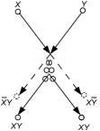
The variables and represent local concentrations of an activator, or an excitatory component of BZ system, and an inhibitor, or a refractory component. Parameter sets up a ratio of time scale of variables and , is a scaling parameter depending on rates of activation/propagation and inhibition, is a stoichiometric coefficient. Constant is a rate of inhibitor production. In a light-sensitive BZ represents the rate of inhibitor production proportional to intensity of illumination. We integrate the system using Euler method with five-node Laplace operator, time step and grid point spacing , , , , , . To generate excitation waves of wave-fragments we perturb the medium by a square solid domains of excitation, sites (unless otherwise stated) in state . The parameter characterises excitability of the simulated medium. The medium is excitable, it exhibits ‘classical’ target waves when . The medium is non-excitable when . The medium is sub-excitable with propagating localizations, or wave-fragments, when (Fig. 1).
We guide wave-fragment by constraining them to excitable channels and by colliding the wave-fragments with each other at the junctions of the channels adamatzky2015binary . The channels used in the designs presented have width 30 nodes. At most junctions channels intersect at a right angle to keep ‘contact size’ between the channels minimal and thus to reduce chances of a single wave propagating along one channel to ‘spread’ into another channel.
There are two type of junctions: excitable and sub-excitable. In the excitable junction, as in the channels, . In the sub-excitable junction, each node being at a distance less than 15 nodes from the centre of the junction has , on the design schemes all nodes of the junctions inside the circles has .
There are three scenarios of a wave crossing the junction. If the junction is excitable () the wave spreads in all channels. If the junction is sub-excitable () and only one wave approaches the junction, this lonely wave is transformed to a wave-fragment which crosses the junction conserving its shape. If two wave enter the sub-excitable junction, they collide and fuse into a single wave-fragment.
Time lapse snapshots provided in the paper were recorded at every 150 time steps, we display sites with . Videos supplementing figures were produced by saving a frame of the simulation every 10th step of numerical integration and assembling them in the video with play rate 30 fps.
III Design principles


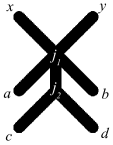
A collision-based computation, inspired by Fredkin-Toffoli conservative logic fredkin2002conservative , employs mobile compact finite patterns which implement computation while interacting with each adamatzky2002collision . Information values (e.g. truth values of logical variables) are given by either absence or presence of the localisations or other parameters of the localisations. The localisations travel in space and perform computation when they collide with each other. Almost any part of the medium space can be used for computation. The localisations undergo transformations, they change velocities, form bound states, annihilate or fuse when they interact with other localisations. Information values of localisations are transformed in the collisions and thus a computation is implemented. The concept of the collision-based logical gates with excitation wave-fragments is best illustrated using a gate based on collision between two soft balls, the Margolus gate margolus2002universal , shown in Fig. 2a. Logical value is given by a ball presented in input trajectory marked , and by absence of the ball in the input trajectory ; the same applies to and . When two balls approaching the collision gate along paths and collide, they compress but then spring back and reflect. The balls come out along the paths marked . If only one ball approaches the gate, for inputs and or and , the ball exits the gate via path (for input and ) or (for input and ).
The Margolus gate is implemented by straightforward mapping of balls trajectories (Fig. 2a) to a configuration of excitable channels (Fig. 2b). Junction is sub-excitable (). Junction is excitable (). Functioning of the gate is shown in Fig. 2c–i and the representation of logical values on each segment of the gate in Tab 2a. If inputs are and the input channel excited (Fig. 2c). The wave-fragment propagates across junction into output ; the wave does not spread into because the junction is sub-excitable. If inputs are and the input is excited (Fig. 2d). The wave-fragment propagates across junction into output ; the wave does not spread into because the junction is sub-excitable. If inputs are and both input channels are excited (Fig. 2e). The wave-fragments propagating along channels and collide at junction : they fuse into a single wave-fragment which enters segment . On reaching the excitable junction the wave-fragment splits into two wave-fragments. One wave propagates into segment , another wave into segment . Excitation wave appears at output only if channel was not excited and channel was excited. Thus we have . Excitation wave appears at output only if channel was excited and channel was not excited. Thus we have . Excitation wave propagating along segment imitates two soft balls propagating as a single body for some time after their collision (Fig. 2a). Splitting of the wave-fragment into segments and (Fig. 2e) imitates soft balls springing back and reflecting (Fig. 2a): and .
| Segment | Value |
|---|---|
| Segment | Value |
|---|---|
| Segment | Value |
|---|---|
IV Implementation of Fredkin gate
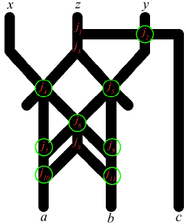


Design of excitable implementation of Fredkin gate consists of ten excitable channels intersecting at eleven junctions (Fig. 3). All junctions but , , are sub-excitable. The exact domains of sub-excitable ares shown in circles in Fig. 3. The gate implement transformation of the Boolean triple to . Inputs , or are represented by excitations initiated at the entrances of the input channels; if an input variable is ‘0’ the corresponding input channel is not excited. Outputs , , are assumed to have value ‘1’ when an excitation wave appears at the corresponding output.
Input , , . Excitation wave is initiated at entrance of channel (Fig. 4a). The wave propagates along segment . Junction is excitable therefore the wave enters segments and . The wave entered propagates across sub-excitable junction into segment without spreading into segment ; this wave reaches the output . The wave propagating in segment splits into two waves at the excitable junction . One wave propagates along and another along . Junctions and are sub-excitable therefore the waves run across the junctions and get extinguished in the cul-de-sacs.
Input , , . Excitation wave is initiated in channel . The wave crosses sub-excitable junction without spreading to neighbouring segments and but propagates only into . Junctions and are sub-excitable. The excitation wave runs across these two junctions without spreading to neighbouring segments. When the wave reaches junction it collides with the wall of the segment , slightly reflect and proceeds towards output (Fig. 4b).
Input , , . Input channels and are excited. Excitation wave-fronts propagate in and (Fig. 4c). The wave-front originated in travels across sub-excitable junction into segment without expanding into segments and . The wave-front originated in spreads into , , (where the excitation dies) and . The wave-fronts propagating along and collides at sub-excitable junction . These two wave-fronts collide because distance from to equals to distance from to . The wave-fronts merge on ‘impact’ and fuse into a single excitation wave-front propagating into . Junctions and are sub-excitable therefore the wave-front cross them without expanding, moving directly to output . The wave-front propagating along crossed junction without expanding and reaches output . Note that on the time-lapsed snapshots (Fig. 4c) traces of wave-fronts travelling from to and form to intersect: wave-fronts per se do not collide because distance from to is large than distance from to . See videos at https://drive.google.com/open?id=0BzPSgPF_2eyUSjM2aWZlU21fM3c.
Input , , . The excitation dynamics is analogous to the dynamics for inputs , , . The wave-fragment initiated at propagates along along path to to to to to (Fig. 4d).
Input , , . Excitation wave-front originated in collides with excitation wave-front originated in at junction . The wave-front fuse into a single wave-front. This front travels along . Junction is excitable therefore the wave-front spreads into segments and and to outputs and (Fig. 4e).
Input , , . Excitation initiated in propagates towards (Fig. 4f). Excitation initiated in propagates along path to output and also along path to junction . Distance from to is the same as distance from to . Therefore wave-fronts travelling along paths and collide with each other. They fuse into a single excitation wave-front. This wave-front propagates to output .
Input , , . Excitations are initiated in all three inputs (Fig. 4g). Wave-fronts originated in and collide with each other at junction . They fuse into a wave-fragment travelling towards output . Wave-fronts originated in and collide with each other at junction . They fuse into a wave-fragment travelling towards output . The excitation wave-front from also travels to output .
Thus, we have , , . Exact Boolean functions represented by a wave-fragment on each of the segments are shown in Tab. 2b.
In design Figs. 3 and 4 the path from to is longer than paths from , or to and therefore a signal arrives at output later than signals arrived at outputs and . This can be amended by making output segments and longer by transforming them in zig-zag segments. We did not show this compensation on the scheme or video not to clutter the designs.
V Implementation of Toffoli gate
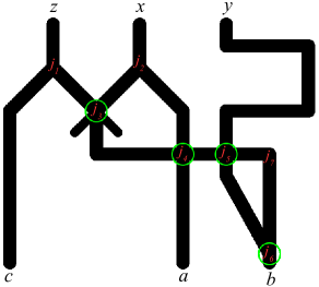


An excitable medium device implementing Toffoli gate (Fig. 5) consists of six excitable channels intersecting at six junctions four of which — , , — are sub-excitable.
Input , , . Excitation wave-fragment propagates from to (Fig. 6a). Junction is sub-excitable therefore the wave-fragment travels across the junction without spreading into lateral openings. The excitation front reaches output .
Input , , . Wave-front initiated in splits into two wave-front at excitable junction . The wave travelling along enters the cul-de-sac and dies. The wave running along reaches the output (Fig. 6b).
Input , , . Paths leading from to and from to do not intersect, therefore wave-fragments originated in and do not interact. Dynamics of excitation is an super-position of the excitation scenarios , , and , , (Fig. 6c).
Input , , . Excitation wave-front travels from to (Fig. 6d). At the wave-front splits into segment , where it reaches output , and segment , where the wave-front dies in the cul-de-sac after crossing the junction.
Input , , . Wave-fronts originating in and do not interact. The wave-front started in reaches output , the wave-front initiated in reaches output (Fig. 6e).
Input , , . Wave-fronts from and propagate to outputs and , respectively. They also propagate along segments and and collide at junction . They fuse and travel as a single wave-front along and ; this wave-front appears at output (Fig. 6f). Not that traces of wave-fragments along paths to and to intersect on the time-lapsed snapshot (Fig. 6f) however wave-fragments do not collide at junction because they enter the junction at different times.
Input , , . Wave-fronts from and propagate to outputs and , respectively (Fig. 6g). They also propagate along segments and and collide at junction . They fuse and travel as a single wave-front along and . Wave-front from travels towards . Distance from (or ) to is the same distance from to . Therefore wave-front travelling from to collides at junction with wave-front travelling from to . These two wave-fronts merge into a single wave-front, which collides into a separation between segments and , the wave-front annihilates (Fig. 6g). Not that traces of wave-fragments along paths to and to intersect on the time-lapsed snapshot (Fig. 6g) however wave-fragments do not collide at junction because they enter the junction at different times.
Thus, we have , , . Exact Boolean represented by a wave-fragment on each of the segments is shown in Tab. 2c.
VI On physical reversibility


The designs of BZ implementation of collision-based gates are logically reversible but not physically reversible (under ’physical reversibility’ we mean only that swapping inputs with outputs not reversibility of chemical reactions or excitation processes). Take for example implementation of Margolus gate (Fig. 2ab). Assume output channels in the original Margolus gate are inputs, and inputs in the original Margolus gate are outputs. If all inputs but are ’0’ excitation is initiated only in channel (Fig. 7b). The wave-fragment propagates into junction where it collides to a protruding non-excitable separator of segments and . The wave-fragment changes its direction of movement in the result of collision and therefore propagates into segment (Fig. 7b). Analogically, if only is excited the excitation wave-front exits the gate through output (Fig. 7c). If is excited the wave-fragment propagates straight into output ; if is excited the wave-fragment propagates into . When both channels and are excited two excitation wave-fragments fuse into a single wave-fragments; this wave collides into a protruding separators between segments and , and this wave annihilates (Fig. 7d). When and are excited the wave-front is formed in segment . This wave-fragment splits into two wave-fragments propagating into segments and . Thus, we have and .
If we apply input signals to channels , , of Fredkin and Toffoli gates we get the following output signals on channels , , .
If inputs are swapped with output in the Fredkin gate (Fig. 3) then , , . Wave-fronts representing signals generated at , and do not interact with each other. If at least one of the channels , or is excited the wave-front always propagates into channel . Wave-front starting at splits at and goes into and . Wave from splits at and propagates to and . Wave initiated at propagates along path to to to . Thus we have . Excitation wave-front gets into only if channel is excited, thus . Channel gets excited only if excitation wave is initiated in channel , thus .
If inputs are swapped with outputs in Toffoli gate (Fig. 5) then , , . Only excitation wave-front initiated at channel can excite , and . This is because excitation wave splits at the junction and thus excitation propagates along paths to to to (splits in ) to and . At the same time, the wave propagates from to to to . Channel is only excited from , thus we have . Channel can be excited by wave-fronts initiated at or at , thus . Channel is excited from or , thus .
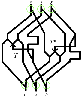
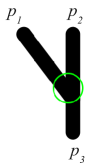


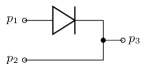
To make physically — at a macro-level not at the level of chemical reactions — reversible gates we can take two copies of the original gate (Fig. 5) flip one copy around an axis perpendicular to inputs and link these two sub-circuits in a single-circuit as shown in Fig. 8. Original copy of Toffoli gate is labelled in Fig. 8, and flipped version . A routing of input signals between and is implemented using sub-excitable junctions encircled in Fig. 8. The junction functioning is illustrated in Fig. 9. When a wave-front is initiated either at port (Fig. 9b) or (Fig. 9c) the wave-front propagates towards port without back-spreading into port (). When a wave-front is initiated at port it propagates towards the port only (Fig. 9d) but does not enter the channel leading to port . In terms of electrical circuits, this is analogous of having a diode at connection (Fig. 9e).
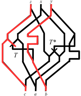
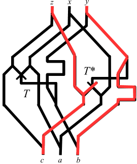
Two examples of the circuit responding to and inputs are shown in Fig. 8c. When signals enter the circuit via , or the excitation waves propagate into the sub-circuit , the signals entered , or are routed into the sub-circuit . An example of traces of excitation propagation when signals are applied to inputs , , is shown in Fig. 8b; and, when signals are applied to inputs , , in Fig. 8c.
VII Discussion
The architectures of Fredkin and Toffoli gates proposed are evaluated in numerical model of a light sensitive Belousov-Zhabotinsky (BZ) reaction. Advantage of the light-sensitive BZ is that there is no need for altering a homogeneous substrate: an architecture of computing circuits is projected with light onto the medium such that conductive channels are non-illuminated and non-conductive domains are illuminated. Further studies might also focus on mapping the designs in molecular arrays DBLP:journals/ijuc/Reif12 ; DBLP:journals/ijuc/KonkoliW14 ; valleau2012exciton ; saikin2013photonics ; arrays of single-electron oscillators,, locally coupled with capacitors oya2005reaction , solid state reaction-diffusion devices with minority-carrier diffusion asai2001novel ; takahashi2007cmos ; CNN chips, where pairs of layers represent activator and inhibitor concentrations, and diffusion and reaction are controlled via external bias voltages shi2004spatial ; arena1999realization ; rekeczky2000stored ; petras2003exploration ; arena2004cnn ; bonaiuto2000design ; karahaliloglu2004mos . Unconventional robotics is another application domain. The BZ computing circuits can be integrated with self-propulsive BZ droplets suematsu2016oscillation . The BZ circuits can play a key role in embedded parallel controllers for soft robots made of pH sensitive polymers and gels yashin2006modeling ; yoshida1999aspects ; maeda2008control ; yoshida2010self , especially to implement decision-making circuits for crawling robots made of BZ gels ren2016retrograde as processors complimentary to a fluidic logic rus2015design ; nawaz2013unconventional ; wehner2016integrated .
References
- [1] Andrew Adamatzky. Collision-based computing in Belousov–Zhabotinsky medium. Chaos, Solitons & Fractals, 21(5):1259–1264, 2004.
- [2] Andrew Adamatzky. Slime mould logical gates: exploring ballistic approach. arXiv preprint arXiv:1005.2301, 2010.
- [3] Andrew Adamatzky. Binary full adder, made of fusion gates, in a subexcitable Belousov-Zhabotinsky system. Physical Review E, 92(3):032811, 2015.
- [4] Andrew Adamatzky, Ben de Lacy Costello, and Larry Bull. On polymorphic logical gates in subexcitable chemical medium. International Journal of Bifurcation and Chaos, 21(07):1977–1986, 2011.
- [5] Andrew Adamatzky, Ben De Lacy Costello, Larry Bull, and Julian Holley. Towards arithmetic circuits in sub-excitable chemical media. Israel Journal of Chemistry, 51(1):56–66, 2011.
- [6] Andrew Adamatzky and Benjamin de Lacy Costello. Collision-free path planning in the Belousov-Zhabotinsky medium assisted by a cellular automaton. Naturwissenschaften, 89(10):474–478, 2002.
- [7] Andrew Adamatzky and Benjamin de Lacy Costello. Binary collisions between wave-fragments in a sub-excitable Belousov–Zhabotinsky medium. Chaos, Solitons & Fractals, 34(2):307–315, 2007.
- [8] Andrew Adamatzky, Benjamin de Lacy Costello, Chris Melhuish, and Norman Ratcliffe. Experimental implementation of mobile robot taxis with onboard Belousov–Zhabotinsky chemical medium. Materials Science and Engineering: C, 24(4):541–548, 2004.
- [9] Takashi Amemiya, Takao Ohmori, Masaru Nakaiwa, and Tomohiko Yamaguchi. Two-parameter stochastic resonance in a model of the photosensitive Belousov-Zhabotinsky reaction in a flow system. The Journal of Physical Chemistry A, 102(24):4537–4542, 1998.
- [10] Paolo Arena, Adriano Basile, Luigi Fortuna, and Mattia Frasca. Cnn wave based computation for robot navigation planning. In Circuits and Systems, 2004. ISCAS’04. Proceedings of the 2004 International Symposium on, volume 5, pages V–500. IEEE, 2004.
- [11] Paolo Arena, Luigi Fortuna, and Marco Branciforte. Realization of a reaction-diffusion cnn algorithm for locomotion control in an hexapode robot. Journal of VLSI signal processing systems for signal, image and video technology, 23(2-3):267–280, 1999.
- [12] Tetsuya Asai, Yuusaku Nishimiya, and Yoshihito Amemiya. A novel reaction-diffusion system based on minority-carrier transport in solid-state cmos devices. In Semiconductor Device Research Symposium, 2001 International, pages 141–144. IEEE, 2001.
- [13] Arash Azhand, Jan Frederik Totz, and Harald Engel. Three-dimensional autonomous pacemaker in the photosensitive Belousov-Zhabotinsky medium. EPL (Europhysics Letters), 108(1):10004, 2014.
- [14] Adriano Barenco, Charles H Bennett, Richard Cleve, David P DiVincenzo, Norman Margolus, Peter Shor, Tycho Sleator, John A Smolin, and Harald Weinfurter. Elementary gates for quantum computation. Physical review A, 52(5):3457, 1995.
- [15] Valentina Beato and Harald Engel. Pulse propagation in a model for the photosensitive Belousov-Zhabotinsky reaction with external noise. In SPIE’s First International Symposium on Fluctuations and Noise, pages 353–362. International Society for Optics and Photonics, 2003.
- [16] Boris P Belousov. A periodic reaction and its mechanism. Compilation of Abstracts on Radiation Medicine, 147(145):1, 1959.
- [17] Charles H Bennett. Notes on the history of reversible computation. IBMs Journal of Research and Development, 32(1):16–23, 1988.
- [18] Gennady P Berman, Gary D Doolen, Darryl D Holm, and Vladimir I Tsifrinovich. Quantum computer on a class of one-dimensional Ising systems. Physics Letters A, 193(5-6):444–450, 1994.
- [19] V Bonaiuto, A Maffucci, G Miano, M Salerno, F Sargeni, and C Visone. Design of a cellular nonlinear network for analogue simulation of reaction-diffusion pdes. In Circuits and Systems, 2000. Proceedings. ISCAS 2000 Geneva. The 2000 IEEE International Symposium on, volume 3, pages 431–434. IEEE, 2000.
- [20] NJ Cerf, C Adami, and PG Kwiat. Optical simulation of quantum logic. Physical Review A, 57(3):R1477, 1998.
- [21] Hsu Chang. Magnetic-bubble conservative logic. International Journal of Theoretical Physics, 21(12):955–960, 1982.
- [22] David G Cory, Mark D Price, and Timothy F Havel. Nuclear magnetic resonance spectroscopy: An experimentally accessible paradigm for quantum computing. Physica D: Nonlinear Phenomena, 120(1):82–101, 1998.
- [23] Ben De Lacy Costello, Andy Adamatzky, Ishrat Jahan, and Liang Zhang. Towards constructing one-bit binary adder in excitable chemical medium. Chemical Physics, 381(1):88–99, 2011.
- [24] Robert Cuykendall and Debra McMillin. Control-specific optical Fredkin circuits. Applied optics, 26(10):1959–1963, 1987.
- [25] Ben de Lacy Costello, Rita Toth, Christopher Stone, Andrew Adamatzky, and Larry Bull. Implementation of glider guns in the light-sensitive Belousov-Zhabotinsky medium. Physical Review E, 79(2):026114, 2009.
- [26] Alexis De Vos. Reversible computing: fundamentals, quantum computing, and applications. John Wiley & Sons, 2011.
- [27] JD Dockery, James P Keener, and JJ Tyson. Dispersion of traveling waves in the Belousov-Zhabotinskii reaction. Physica D: Nonlinear Phenomena, 30(1):177–191, 1988.
- [28] Gabi Escuela, Gerd Gruenert, and Peter Dittrich. Symbol representations and signal dynamics in evolving droplet computers. Natural Computing, 13(2):247–256, 2014.
- [29] Xue Fei, Du Jiang-Feng, Shi Ming-Jun, Zhou Xian-Yi, Han Rong-Dian, and Wu Ji-Hui. Realization of the Fredkin gate by three transition pulses in a nuclear magnetic resonance quantum information processor. Chinese physics letters, 19(8):1048, 2002.
- [30] Richard J Field and Richard M Noyes. Oscillations in chemical systems. iv. limit cycle behavior in a model of a real chemical reaction. The Journal of Chemical Physics, 60(5):1877–1884, 1974.
- [31] Brian E Fratto, Nataliia Guz, and Evgeny Katz. Biomolecular computing realized in parallel flow systems: Enzyme-based double feynman logic gate. Parallel Processing Letters, 25(01):1540001, 2015.
- [32] Brian E Fratto and Evgeny Katz. Reversible logic gates based on enzyme-biocatalyzed reactions and realized in flow cells: A modular approach. ChemPhysChem, 16(7):1405–1415, 2015.
- [33] Brian E Fratto and Evgeny Katz. Controlled logic gates switch gate and fredkin gate based on enzyme-biocatalyzed reactions realized in flow cells. ChemPhysChem, 2016.
- [34] Brian E Fratto and Evgeny Katz. Utilization of a fluidic infrastructure for the realization of enzyme-based Boolean logic operations. International Journal of Parallel, Emergent and Distributed Systems, pages 1–18, 2016.
- [35] Edward Fredkin and Tommaso Toffoli. Conservative logic. In Collision-based computing, pages 47–81. Springer, 2002.
- [36] Pier Luigi Gentili, Viktor Horvath, Vladimir K Vanag, and Irving R Epstein. Belousov-Zhabotinsky “chemical neuron” as a binary and fuzzy logic processor. IJUC, 8(2):177–192, 2012.
- [37] J Gorecka and J Gorecki. T-shaped coincidence detector as a band filter of chemical signal frequency. Physical Review E, 67(6):067203, 2003.
- [38] J Gorecki, K Gizynski, J Guzowski, JN Gorecka, P Garstecki, G Gruenert, and P Dittrich. Chemical computing with reaction–diffusion processes. Phil. Trans. R. Soc. A, 373(2046):20140219, 2015.
- [39] J Gorecki, JN Gorecka, and Andrew Adamatzky. Information coding with frequency of oscillations in Belousov-Zhabotinsky encapsulated disks. Physical Review E, 89(4):042910, 2014.
- [40] J Gorecki, K Yoshikawa, and Y Igarashi. On chemical reactors that can count. The Journal of Physical Chemistry A, 107(10):1664–1669, 2003.
- [41] Jerzy Gorecki and Joanna Natalia Gorecka. Information processing with chemical excitations–from instant machines to an artificial chemical brain. International Journal of Unconventional Computing, 2(4), 2006.
- [42] Jerzy Gorecki, Joanna Natalia Gorecka, and Yasuhiro Igarashi. Information processing with structured excitable medium. Natural Computing, 8(3):473–492, 2009.
- [43] Gerd Gruenert, Konrad Gizynski, Gabi Escuela, Bashar Ibrahim, Jerzy Gorecki, and Peter Dittrich. Understanding networks of computing chemical droplet neurons based on information flow. International journal of neural systems, page 1450032, 2014.
- [44] Gerd Gruenert, Konrad Gizynski, Gabi Escuela, Bashar Ibrahim, Jerzy Gorecki, and Peter Dittrich. Understanding networks of computing chemical droplet neurons based on information flow. International journal of neural systems, 25(07):1450032, 2015.
- [45] Shan Guo, Ming-Zhu Sun, and Xin Han. Digital comparator in excitable chemical media. International Journal Unconventional Computing, 2015.
- [46] James Hardy and Joseph Shamir. Optics inspired logic architecture. Optics Express, 15(1):150–165, 2007.
- [47] Harold M Hastings, Richard Jeffrey Field, Sabrina Godfrey Sobel, and David Guralnick. Oregonator scaling motivated by showalter-noyes limit. The Journal of Physical Chemistry A, 2016.
- [48] TJ Hsu, CY Mou, and DJ Lee. Effects of macromixing on the oregonator model of the belousov zhabotinsky reaction in a stirred reactor. Chemical engineering science, 49(24):5291–5305, 1994.
- [49] Yasuhiro Igarashi and Jerzy Gorecki. Chemical diodes built with controlled excitable media. IJUC, 7(3):141–158, 2011.
- [50] Yasuhiro Igarashi, Jerzy Gorecki, and Joanna Natalia Gorecka. Chemical information processing devices constructed using a nonlinear medium with controlled excitability. In Unconventional Computation, pages 130–138. Springer, 2006.
- [51] W Jahnke, WE Skaggs, and Arthur T Winfree. Chemical vortex dynamics in the Belousov-Zhabotinskii reaction and in the two-variable oregonator model. The Journal of Physical Chemistry, 93(2):740–749, 1989.
- [52] Akiko Kaminaga, Vladimir K Vanag, and Irving R Epstein. A reaction–diffusion memory device. Angewandte Chemie International Edition, 45(19):3087–3089, 2006.
- [53] Koray Karahaliloglu and Sina Balkir. An mos cell circuit for compact implementation of reaction-diffusion models. In Neural Networks, 2004. Proceedings. 2004 IEEE International Joint Conference on, volume 1. IEEE, 2004.
- [54] Evgeny Katz and Brian E Fratto. Enzyme-based reversible logic gates operated in flow cells. In Advances in Unconventional Computing, pages 29–59. Springer, 2017.
- [55] Joshua P Klein, Thomas H Leete, and Harvey Rubin. A biomolecular implementation of logically reversible computation with minimal energy dissipation. Biosystems, 52(1):15–23, 1999.
- [56] Zoran Konkoli and Göran Wendin. On information processing with networks of nano-scale switching elements. IJUC, 10(5-6):405–428, 2014.
- [57] Natalie Kostinski, Mable P Fok, and Paul R Prucnal. Experimental demonstration of an all-optical fiber-based Fredkin gate. Optics letters, 34(18):2766–2768, 2009.
- [58] Hans Juergen Krug, Ludwig Pohlmann, and Lothar Kuhnert. Analysis of the modified complete oregonator accounting for oxygen sensitivity and photosensitivity of Belousov-Zhabotinskii systems. Journal of Physical Chemistry, 94(12):4862–4866, 1990.
- [59] L Kuhnert. A new optical photochemical memory device in a light-sensitive chemical active medium. 1986.
- [60] Lothar Kuhnert, KI Agladze, and VI Krinsky. Image processing using light-sensitive chemical waves. 1989.
- [61] Alberto Leporati, Claudio Zandron, and Giancarlo Mauri. Simulating the Fredkin gate with energy-based p systems. J. UCS, 10(5):600–619, 2004.
- [62] Seth Lloyd et al. A potentially realizable quantum computer. Science, 261(5128):1569–1571, 1993.
- [63] Shingo Maeda, Yusuke Hara, Ryo Yoshida, and Shuji Hashimoto. Control of the dynamic motion of a gel actuator driven by the Belousov-Zhabotinsky reaction. Macromolecular Rapid Communications, 29(5):401–405, 2008.
- [64] Norman Margolus. Universal cellular automata based on the collisions of soft spheres. In Andrew Adamatzky, editor, Collision-based computing, pages 107–134. Springer, 2002.
- [65] GJ Milburn. Quantum optical Fredkin gate. Physical Review Letters, 62(18):2124, 1989.
- [66] Fiona Moseley, Jan Halámek, Friederike Kramer, Arshak Poghossian, Michael J Schöning, and Evgeny Katz. An enzyme-based reversible cnot logic gate realized in a flow system. Analyst, 139(8):1839–1842, 2014.
- [67] KVRM Murali, Neeraj Sinha, TS Mahesh, Malcolm H Levitt, KV Ramanathan, and Anil Kumar. Quantum-information processing by nuclear magnetic resonance: Experimental implementation of half-adder and subtractor operations using an oriented spin-7/2 system. Physical Review A, 66(2):022313, 2002.
- [68] Ahmad Ahsan Nawaz, Xiaole Mao, Zackary S Stratton, and Tony Jun Huang. Unconventional microfluidics: expanding the discipline. Lab on a Chip, 13(8):1457–1463, 2013.
- [69] Ron Orbach, Francoise Remacle, RD Levine, and Itamar Willner. Dnazyme-based 2: 1 and 4: 1 multiplexers and 1: 2 demultiplexer. Chemical Science, 5(3):1074–1081, 2014.
- [70] Takahide Oya, Tetsuya Asai, Takashi Fukui, and Yoshihito Amemiya. Reaction-diffusion systems consisting of single-electron oscillators. International Journal of Unconventional Computing, 1(2):179, 2005.
- [71] István Petrás, Csaba Rekeczky, Tamás Roska, Ricardo Carmona, Francisco Jiménez-Garrido, and Angel Rodríguez-Vázquez. Exploration of spatial-temporal dynamic phenomena in a 32 32-cell stored program two-layer cnn universal machine chip prototype. Journal of Circuits, Systems, and Computers, 12(06):691–710, 2003.
- [72] AJ Poustie and KJ Blow. Demonstration of an all-optical Fredkin gate. Optics Communications, 174(1):317–320, 2000.
- [73] Srinivasa R Pullela, Diego Cristancho, Peng He, Dawei Luo, Kenneth R Hall, and Zhengdong Cheng. Temperature dependence of the oregonator model for the Belousov-Zhabotinsky reaction. Physical Chemistry Chemical Physics, 11(21):4236–4243, 2009.
- [74] NG Rambidi and D Yakovenchuk. Chemical reaction-diffusion implementation of finding the shortest paths in a labyrinth. Physical Review E, 63(2):026607, 2001.
- [75] John H. Reif. Local parallel biomolecular computation. IJUC, 8(5-6):459–507, 2012.
- [76] Csaba Rekeczky, T Serrano-Gotarredona, Tamás Roska, and A Rodriguez-Vazquez. A stored program 2 nd order/3-layer complex cell cnn-um. In Cellular Neural Networks and Their Applications, 2000.(CNNA 2000). Proceedings of the 2000 6th IEEE International Workshop on, pages 213–217. IEEE, 2000.
- [77] Lin Ren, Weibing She, Qingyu Gao, Changwei Pan, Chen Ji, and Irving R Epstein. Retrograde and direct wave locomotion in a photosensitive self-oscillating gel. Angewandte Chemie, 2016.
- [78] Sukhdev Roy and Mohit Prasad. Novel proposal for all-optical Fredkin logic gate with bacteriorhodopsin-coated microcavity and its applications. Optical Engineering, 49(6):065201–065201, 2010.
- [79] Daniela Rus and Michael T Tolley. Design, fabrication and control of soft robots. Nature, 521(7553):467–475, 2015.
- [80] Semion K Saikin, Alexander Eisfeld, Stéphanie Valleau, and Alán Aspuru-Guzik. Photonics meets excitonics: natural and artificial molecular aggregates. Nanophotonics, 2(1):21–38, 2013.
- [81] Andrew Schumann. Conventional and unconventional reversible logic gates on physarum polycephalum. International Journal of Parallel, Emergent and Distributed Systems, pages 1–14, 2015.
- [82] Georg Seelig, David Soloveichik, David Yu Zhang, and Erik Winfree. Enzyme-free nucleic acid logic circuits. science, 314(5805):1585–1588, 2006.
- [83] Hana Šev?íková, Igor Schreiber, and Miloš Marek. Dynamics of oxidation Belousov-Zhabotinsky waves in an electric field. The Journal of Physical Chemistry, 100(49):19153–19164, 1996.
- [84] Joseph Shamir, H John Caulfield, William Micelli, and Robert J Seymour. Optical computing and the Fredkin gates. Applied optics, 25(10):1604–1607, 1986.
- [85] Bertram E Shi and Tao Luo. Spatial pattern formation via reaction-diffusion dynamics in 32 32 4 cnn chip. IEEE Transactions on Circuits and Systems I: Regular Papers, 51(5):939–947, 2004.
- [86] Jakub Sielewiesiuk and Jerzy Górecki. Logical functions of a cross junction of excitable chemical media. The Journal of Physical Chemistry A, 105(35):8189–8195, 2001.
- [87] John A Smolin and David P DiVincenzo. Five two-bit quantum gates are sufficient to implement the quantum Fredkin gate. Physical Review A, 53(4):2855, 1996.
- [88] Oliver Steinbock, Petteri Kettunen, and Kenneth Showalter. Chemical wave logic gates. The Journal of Physical Chemistry, 100(49):18970–18975, 1996.
- [89] Oliver Steinbock, Ágota Tóth, and Kenneth Showalter. Navigating complex labyrinths: optimal paths from chemical waves. Science, pages 868–868, 1995.
- [90] William M Stevens, Andrew Adamatzky, Ishrat Jahan, and Ben de Lacy Costello. Time-dependent wave selection for information processing in excitable media. Physical Review E, 85(6):066129, 2012.
- [91] James Stovold and Simon O Keefe. Simulating neurons in reaction-diffusion chemistry. In International Conference on Information Processing in Cells and Tissues, pages 143–149. Springer, 2012.
- [92] James Stovold and Simon O Keefe. Reaction–diffusion chemistry implementation of associative memory neural network. International Journal of Parallel, Emergent and Distributed Systems, pages 1–21, 2016.
- [93] James Stovold and Simon O Keefe. Associative memory in reaction-diffusion chemistry. In Advances in Unconventional Computing, pages 141–166. Springer, 2017.
- [94] Nobuhiko J Suematsu, Yoshihito Mori, Takashi Amemiya, and Satoshi Nakata. Oscillation of speed of a self-propelled belousov–zhabotinsky droplet. The Journal of Physical Chemistry Letters, 7(17):3424–3428, 2016.
- [95] Ming-Zhu Sun and Xin Zhao. Multi-bit binary decoder based on Belousov-Zhabotinsky reaction. The Journal of chemical physics, 138(11):114106, 2013.
- [96] Ming-Zhu Sun and Xin Zhao. Crossover structures for logical computations in excitable chemical medium. International Journal Unconventional Computing, 2015.
- [97] JJ Taboada, AP Munuzuri, V Pérez-Muñuzuri, M Gómez-Gesteira, and V Pérez-Villar. Spiral breakup induced by an electric current in a belousov–zhabotinsky medium. Chaos: An Interdisciplinary Journal of Nonlinear Science, 4(3):519–524, 1994.
- [98] Motoyoshi Takahashi, Tetsuya Asai, Tetsuya Hirose, and Yoshihito Amemiya. A cmos reaction-diffusion device using minority-carrier diffusion in semiconductors. International Journal of Bifurcation and Chaos, 17(05):1713–1719, 2007.
- [99] Hisako Takigawa-Imamura and Ikuko N Motoike. Dendritic gates for signal integration with excitability-dependent responsiveness. Neural Networks, 24(10):1143–1152, 2011.
- [100] Tommaso Toffoli. Reversible computing. In International Colloquium on Automata, Languages, and Programming, pages 632–644. Springer, 1980.
- [101] Kazuhisa Tomita and Ichiro Tsuda. Chaos in the Belousov-Zhabotinsky reaction in a flow system. Physics Letters A, 71(5):489–492, 1979.
- [102] Rita Toth, Christopher Stone, Andrew Adamatzky, Ben de Lacy Costello, and Larry Bull. Experimental validation of binary collisions between wave fragments in the photosensitive Belousov–Zhabotinsky reaction. Chaos, Solitons & Fractals, 41(4):1605–1615, 2009.
- [103] Rita Toth, Christopher Stone, Ben de Lacy Costello, Andrew Adamatzky, and Larry Bull. Simple collision-based chemical logic gates with adaptive computing. Theoretical and Technological Advancements in Nanotechnology and Molecular Computation: Interdisciplinary Gains: Interdisciplinary Gains, page 162, 2010.
- [104] Stéphanie Valleau, Semion K Saikin, Man-Hong Yung, and Alán Aspuru Guzik. Exciton transport in thin-film cyanine dye j-aggregates. The journal of chemical physics, 137(3):034109, 2012.
- [105] Vladimir K Vanag, Anatol M Zhabotinsky, and Irving R Epstein. Pattern formation in the Belousov-Zhabotinsky reaction with photochemical global feedback. The Journal of Physical Chemistry A, 104(49):11566–11577, 2000.
- [106] V. A. Vavilin, A. M. Zhabotinsky, and AN Zaikin. Effect of ultraviolet radiation on oscillating oxidation reaction of malonic acid derivatives, 1968.
- [107] Alejandro Vazquez-Otero, Jan Faigl, Natividad Duro, and Raquel Dormido. Reaction-diffusion based computational model for autonomous mobile robot exploration of unknown environments. IJUC, 10(4):295–316, 2014.
- [108] Michael Wehner, Ryan L Truby, Daniel J Fitzgerald, Bobak Mosadegh, George M Whitesides, Jennifer A Lewis, and Robert J Wood. An integrated design and fabrication strategy for entirely soft, autonomous robots. Nature, 536(7617):451–455, 2016.
- [109] Hai-Rui Wei and Fu-Guo Deng. Compact quantum gates on electron-spin qubits assisted by diamond nitrogen-vacancy centers inside cavities. Physical Review A, 88(4):042323, 2013.
- [110] Josef-Stefan Wenzler, Tyler Dunn, Tommaso Toffoli, and Pritiraj Mohanty. A nanomechanical Fredkin gate. Nano letters, 14(1):89–93, 2013.
- [111] Arthur T Winfree and Wolfgang Jahnke. Three-dimensional scroll ring dynamics in the Belousov-Zhabotinskii reagent and in the two-variable oregonator model. The Journal of Physical Chemistry, 93(7):2823–2832, 1989.
- [112] David Harlan Wood and Chen Junghuei. Fredkin gate circuits via recombination enzymes. In Congress on evolutionary computation, 2004.
- [113] Victor V Yashin and Anna C Balazs. Modeling polymer gels exhibiting self-oscillations due to the Belousov-Zhabotinsky reaction. Macromolecules, 39(6):2024–2026, 2006.
- [114] Hiroshi Yokoi, Andy Adamatzky, Ben de Lacy Costello, and Chris Melhuish. Excitable chemical medium controller for a robotic hand: Closed-loop experiments. International Journal of Bifurcation and Chaos, 14(09):3347–3354, 2004.
- [115] Ryo Yoshida. Self-oscillating gels driven by the Belousov–Zhabotinsky reaction as novel smart materials. Advanced Materials, 22(31):3463–3483, 2010.
- [116] Ryo Yoshida, Satoko Onodera, Tomohiko Yamaguchi, and Etsuo Kokufuta. Aspects of the Belousov-Zhabotinsky reaction in polymer gels. The Journal of Physical Chemistry A, 103(43):8573–8578, 1999.
- [117] Kenichi Yoshikawa, Ikuko Motoike, T. Ichino, T. Yamaguchi, Yasuhiro Igarashi, Jerzy Gorecki, and Joanna Natalia Gorecka. Basic information processing operations with pulses of excitation in a reaction-diffusion system. IJUC, 5(1):3–37, 2009.
- [118] George T Zardalidis and Ioannis Karafyllidis. Design and simulation of a nanoelectronic single-electron universal Fredkin gate. IEEE Transactions on Circuits and Systems I: Regular Papers, 51(12):2395–2403, 2004.
- [119] AM Zhabotinsky. Periodic processes of malonic acid oxidation in a liquid phase. Biofizika, 9(306-311):11, 1964.
- [120] Guo-Mao Zhang, Ieong Wong, Meng-Ta Chou, and Xin Zhao. Towards constructing multi-bit binary adder based on Belousov-Zhabotinsky reaction. The Journal of chemical physics, 136(16):164108, 2012.
- [121] Shi-Biao Zheng. Implementation of Toffoli gates with a single asymmetric Heisenberg x y interaction. Physical Review A, 87(4):042318, 2013.