Fast microwave-driven three-qubit gates for cavity-coupled superconducting qubits
Abstract
Although single and two-qubit gates are sufficient for universal quantum computation, single-shot three-qubit gates greatly simplify quantum error correction schemes and algorithms. We design fast, high-fidelity three-qubit entangling gates based on microwave pulses for transmon qubits coupled through a superconducting resonator. We show that when interqubit frequency differences are comparable to single-qubit anharmonicities, errors occur primarily through a single unwanted transition. This feature enables the design of fast three-qubit gates based on simple analytical pulse shapes that are engineered to minimize such errors. We show that a three-qubit ccz gate can be performed in 260 ns with fidelities exceeding , or with numerical optimization.
Quantum information processing is one of the most exciting and rapidly growing fields of modern science, in large part due to quantum algorithms, which promise exponential speedup in solving important problems. Quantum two-level systems (qubits) are the fundamental carriers of quantum information, and among the most promising of these are qubits based on superconducting circuits Clarke and Wilhelm (2008); Devoret and Schoelkopf (2013). Such an architecture is attractive because of the mature circuit fabrication technology and the ability to couple qubits together via resonators to implement logic gates Majer et al. (2007).
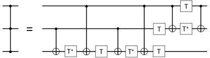
For universal quantum computing, a certain set of high-fidelity logic gates suffices to implement any algorithm; this set is comprised of single-qubit gates along with one maximally entangling two-qubit gate. Three-qubit gates, which play a prominent role in algorithms, can be decomposed in terms of a sequence of single- and two-qubit gates Nielsen and Chuang (2000). In the case of a maximally entangling three-qubit control-control-z (ccz) gate (described below), one must perform seven single-qubit gates and six entangling two-qubit gates, as shown in Fig. 1. The large number of gates needed makes it natural to explore whether a direct, single-shot three-qubit gate is preferable in terms of speed and fidelity.
There are two ways to implement logic gates in superconducting qubit systems. One is via tuning of the energy levels, which brings states into and out of resonance. The other is via oscillating microwave fields that induce transitions between energy levels, which offers the advantage of less susceptibility to charge noise. Both approaches face the challenge of spectral crowding in these systems, especially in the context of superconducting transmon qubits where each qubit is a weakly anharmonic oscillator out of which the two lowest levels are selected to encode information Koch et al. (2007). In the case of many qubits coupled together, there is a large number of closely spaced transitions that need to be avoided during quantum gate operations. Generically, a way to avoid unwanted transitions is to consider the time-energy uncertainty principle, which tells us to make the operations slow. In realistic systems, however, this is not an option, as we need to perform operations at a time scale that is much faster than decay and decoherence.
There has been substantial theoretical effort to design pulses that avoid unwanted dynamics due to ‘harmful’ transitions. A protocol that avoids leakage in single-qubit gates called DRAG has been introduced Motzoi et al. (2009); Forney et al. (2010); Gambetta et al. (2011); Motzoi and Wilhelm (2013); Schutjens et al. (2013) and experimentally used Chow et al. (2010); Chen et al. (2016). For two-qubit gates, various approaches have been developed both for microwave drive Majer et al. (2007); Li et al. (2008); Kelly et al. (2010); Rigetti and Devoret (2010); Yang et al. (2010); Kim et al. (2011); Chow et al. (2012, 2013, 2014); Economou and Barnes (2015) and for tuning Strauch et al. (2003); DiCarlo et al. (2009, 2010); Lucero et al. (2012); Ghosh et al. (2013); Egger and Wilhelm (2014); Martinis and Geller (2014); Barends et al. (2014). In general, techniques developed in the context of one- or two-qubit gates are not directly applicable to three-qubit gates. Over the last few years researchers have used numerical optimal control theory (OCT) techniques to design three-qubit gates Stojanović et al. (2012); Zahedinejad et al. (2015, 2016); Moqadam et al. (2013). Thus far, only tuning-based three-qubit gates have been demonstrated experimentally Fedorov et al. (2011); Mariantoni et al. (2011); Reed et al. (2012). Although many experimental groups are pursuing an all-microwave-control approach, microwave-based three-qubit gates have yet to be implemented in the laboratory, probably because there does not yet exist a simple protocol for them.
In this Letter, we present an analytical protocol for a fast, high fidelity three-qubit gate Economou and Barnes (2015) based on a single microwave pulse. We show that by choosing qubit anharmonicities to be comparable to inter-qubit detunings, the spectrum resembles that of two qubits. In this regime, we can adapt a two-qubit gate protocol that two of us have recently developed Economou and Barnes (2015), known as SWIPHT, to implement a microwave-driven three-qubit gate in 260 ns. We use a hyperbolic secant pulse, which is smooth and experimentally simple to generate. Despite the complexity of the Hilbert space and the simplicity and speed of our pulse, we obtain a gate fidelity exceeding 99.38%. We further show that our analytical solution can be successfully used as a starting point in OCT algorithms. The OCT solution reduces the infidelity by almost two orders of magnitude, pushing the gate fidelity to more than 99.99% without affecting the total gate duration, but at the cost of a more complicated pulse.
The most well known three-qubit gate is the Toffoli gate, which is a not operation on one qubit conditional on the state of the other two qubits, and which is also known as control-control-not (ccnot). The Toffoli gate is equivalent to a ccz gate, which amounts to a z gate (a rotation about the axis) on one of the qubits conditional on the state of the other two qubits. In the computational basis, the ccz gate is a diagonal matrix with a single diagonal element equal to -1, and the rest equal to 1.
The Hamiltonian describing the three-qubit–cavity system is
| (1) |
Here , are creation (annihilation) operators for the cavity and the transmons, respectively, denotes the energy splittings between the first excited state and ground state for each transmon, is the anharmonicity, and is the coupling strength between each transmon and the cavity. We denote the non-interacting (), ‘bare’ eigenstates by , where label the individual transmon states, and where specifies the number of cavity photons. The eigenstates of the full, interacting system described by are denoted by . When the qubits are detuned from each other and from the cavity—a typical situation for superconducting qubits—and for typical qubit-cavity coupling strengths on the order of tens or hundreds of MHz, each dressed eigenstate has a large overlap with one bare state. Accordingly, the energies of the eigenstates are shifted slightly from those of the bare states they originate from. Thus, we use bare state labels to label each interacting, dressed eigenstate according to the bare state with which it has the largest overlap. We define our computational states to be the lowest eight dressed states with zero cavity photons: , with . We omit the cavity photon label when it is zero.
Throughout this work, we focus on the case in which only one transmon is driven, and we take this to be transmon 3. In this case, the full Hamiltonian with driving included is
| (2) |
where and are the pulse envelope and frequency, respectively. The diagonal nature of the ccz gate immediately points to transitionless evolution, i.e., evolution generated by pulses that transfer population between energy eigenstates only transiently and induce phases on the eigenstates. There is a fundamental challenge in inducing a minus sign to only one of the eigenstates while not affecting the remaining ones, and it is related to the generic structure of a three-qubit system. Specifically, it is clear that when we drive one of the three qubits, e.g., transition of qubit 3, there are four states that are near-degenerate: , with describing the 0,1 states of the other two qubits (see Fig. 2). If we attempt to implement the ccz gate by simply selecting narrow-band pulses to resolve the target transition without disturbing the three remaining near-degenerate transitions, we will end up with extremely long pulses.
To speed up the pulse, we employ the basic concept of the SWIPHT method, which we introduced in Economou and Barnes (2015). The main idea behind SWIPHT is to stop trying to avoid the nearly-degenerate transitions, but to instead purposely drive them using a pulse that is properly designed so that the net effect is that the driven states acquire trivial phases. This idea was utilized in Ref. Economou and Barnes (2015) in the context of two cavity-coupled qubits, for which there are two near-degenerate transitions, to implement both the cnot and the cz gate. In the case of the cz gate, which is the two-qubit analogue of our three-qubit ccz gate, a pulse of hyperbolic secant pulse shape was used, which yields an analytically solvable Schrödinger equation Rosen and Zener (1932) for a two-level system. The fact that in the two-qubit case there are two transitions driven simultaneously in a prescribed way allowed us to tune two parameters, the detuning and bandwidth of the pulse, to induce the correct phases on each eigenstate Economou et al. (2006); Economou and Reinecke (2007); Economou (2012).
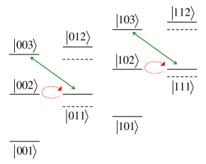
In the present setup, the protocol of Ref. Economou and Barnes (2015) cannot be used straightforwardly due to the existence of the four transitions: the number of pulse parameters is simply less than the number of constraints. We address this issue by taking a second look at the spectrum to explore whether a more advantageous structure can be achieved by appropriately choosing the static parameters, i.e., the qubit and cavity frequencies, the anharmonicity, and the coupling strength (we assume the latter two are the same for all qubits). Out of the four transitions , we aim to isolate two as near-degenerate so that the spectrum will resemble the two-qubit spectrum, which we know how to control. If we choose the frequency of the qubits to differ by the anharmonicity, then the bare state is degenerate with and is degenerate with , which means that the two states and will mix more strongly with the excited states and . As a result, when the third transmon qubit is driven, there will be a significant dipole matrix element between the states and and between the states and . Transitions near these frequencies involving the remaining two states, and , will not be present (see Fig. 2).
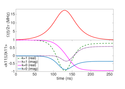
With this spectrum, we are now able to adapt the SWIPHT protocol. We choose the two transitions, and , as the target and the harmful transitions, respectively. We select a hyperbolic secant pulse of area 4, which acts on both transitions simultaneously (see Fig. 3). Applying this pulse resonantly to the harmful transition will drive it strongly, but will only induce a trivial phase of on it. This result is independent of the pulse bandwidth, , which is a free parameter that we can adjust to ensure that the phase acquired by the target transition is -1 as needed for the ccz gate. The analyticity of the solution leads to an explicit result for this phase: , where is the detuning between the two transitions Economou (2012). The value of the bandwidth that achieves is .
So far, our discussion ignores the rest of the Hilbert space and assumes that the presence of the large number of states and transitions not directly involved in our protocol will not affect our result. We now proceed to test this by simulating the dynamics of the full system to assess the performance of our solution in a realistic setup. The system and pulse parameters we use are shown in the caption of Fig. 3. The pulse envelope is shown in the upper panel of the figure, where it can be seen that the total duration is ns. In the simulations, we retain enough states out of the infinite Hilbert space to ensure that the results converge, which amounts to keeping 4 cavity states and 5 states for each of the qubits, resulting in a 500-dimensional Hilbert space. The matrix elements of the evolution operator corresponding to the logical states involved in the target and harmful transitions are shown in the lower panel of Fig. 3. Although deviations from the ideal values and are evident, we will see that these deviations are largely due to the pulse generating additional local operations that can be corrected with single-qubit gates.
We quantify the performance of our ccz gate using the fidelity defined in Ref. Pedersen et al. (2007),
| (3) |
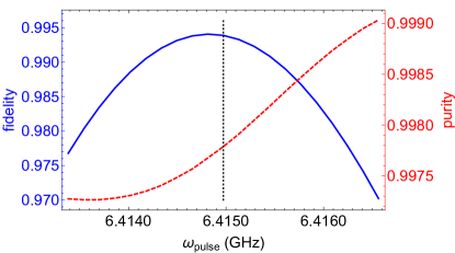
where , is the actual evolution operator truncated to the three-qubit logical subspace, and is the target gate operation. To account for possible local operations, we choose to be a generalized ccz gate which is locally equivalent to the standard ccz up to single-qubit phase gates and a global phase: , and we maximize over the phases . We find that our gate has a fidelity of with phases , , , . Considering the complexity and spectral crowding of the Hilbert space and the simplicity of our pulse shape, this is a remarkable, and perhaps somewhat surprising result. For comparison, even if it were possible to perform every single- and two-qubit gate in the ccz decomposition shown in Fig. 1 with 99.9% fidelity, the fidelity of the resulting ccz gate would be %, while the total duration would exceed a microsecond. The fidelity and purity as a function of the pulse frequency are shown in Fig. 4, where it is evident that the fidelity can be pushed a little higher by shifting the frequency slightly away from resonance with the harmful transition. It is likely that still higher fidelities can be achieved by optimizing with respect to other pulse or system parameters. It is also apparent that the purity grows steadily with pulse frequency, indicating that a larger portion of the error is contained within the logical subspace.
We now address the issue of further increasing the gate fidelity via OCT by using our analytical pulse as a starting point. The idea of OCT is to maximize or minimize a given cost functional based on the Pontryagin maximum principle. Typically this is done by numerically searching for global optima using a gradient based approach such as gradient ascent pulse engineering (GRAPE) Khaneja et al. (2005), which is implemented in the control package in QuTiP Johansson et al. (2012, 2016). Here we use the GRAPE algorithm in order to find the pulse that maximizes the fidelity. If we divide the total evolution time into equispaced time intervals, , on which is assumed to be piecewise constant, the total evolution can be written as a time order product of unitary operators:
| (4) |
where . Denoting by the piecewise constant pulse amplitudes, it is straightforward to calculate the gradient of with respect to , noting that an expression for can be found in Nigmatullin and Schirmer (2009). After having modified the gradient expression in Johansson et al. (2012, 2016) accordingly, we maximized for a total evolution time using time slots and taking the generalized ccz gate with pre-optimized phases as the target gate.
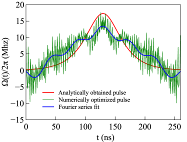
The results are shown in Fig. 5. As an initial guess pulse we took the hyperbolic secant pulse with (smooth red curve), which has the advantage of being already close to the optimal solution. The rapidly modulated (green) curve shows the optimized pulse corresponding to a fidelity of and the slowly modulated (blue) curve shows a Fourier series fit with seven coefficients yielding . Thus, starting from the analytically obtained pulse, the use of OCT can further decrease the infidelity by a few orders of magnitude. We find that using simple, near-optimal analytical pulses as a seed in the numerical optimization algorithm can be dramatically more efficient than blind numerical searches. On the other hand, Fig. 5 suggests that pulses yielding higher fidelities contain significantly higher frequency components, and attempts to smoothen out the fast oscillations lead to a quick saturation of the fidelity to the value obtained for the initial analytical pulse.
In conclusion, we have designed a microwave-based single-shot three-qubit gate for transmon qubits generated by a simple, fast and smooth pulse. Our gate is based on selecting system parameters to obtain a more favorable spectrum, reminiscent of a two-qubit–cavity system. Even without optimizing over parameters or pulse shape, the gate fidelity comfortably exceeds 99%. We have demonstrated that using our analytical pulse as a starting point in optimal control theory leads to a further decrease in the gate infidelity by two orders of magnitude.
References
- Clarke and Wilhelm (2008) J. Clarke and F. K. Wilhelm, Nature 453, 1031 (2008).
- Devoret and Schoelkopf (2013) M. H. Devoret and R. J. Schoelkopf, Science 339, 1169 (2013).
- Majer et al. (2007) J. Majer, J. M. Chow, J. M. Gambetta, J. Koch, B. R. Johnson, J. A. Schreier, L. Frunzio, D. I. Schuster, A. A. Houck, A. Wallraff, et al., Nature 449, 443 (2007).
- Nielsen and Chuang (2000) M. A. Nielsen and I. L. Chuang, Quantum Computation and Quantum Information (Cambridge University Press, Cambridge, England, 2000).
- Koch et al. (2007) J. Koch, T. M. Yu, J. Gambetta, A. A. Houck, D. I. Schuster, J. Majer, A. Blais, M. H. Devoret, S. M. Girvin, and R. J. Schoelkopf, Phys. Rev. A 76, 042319 (2007).
- Motzoi et al. (2009) F. Motzoi, J. M. Gambetta, P. Rebentrost, and F. K. Wilhelm, Phys. Rev. Lett. 103, 110501 (2009).
- Forney et al. (2010) A. M. Forney, S. R. Jackson, and F. W. Strauch, Phys. Rev. A 81, 012306 (2010).
- Gambetta et al. (2011) J. M. Gambetta, F. Motzoi, S. T. Merkel, and F. K. Wilhelm, Phys. Rev. A 83, 012308 (2011).
- Motzoi and Wilhelm (2013) F. Motzoi and F. K. Wilhelm, Phys. Rev. A 88, 062318 (2013).
- Schutjens et al. (2013) R. Schutjens, F. A. Dagga, D. J. Egger, and F. K. Wilhelm, Phys. Rev. A 88, 052330 (2013).
- Chow et al. (2010) J. M. Chow, L. DiCarlo, J. M. Gambetta, F. Motzoi, L. Frunzio, S. M. Girvin, and R. J. Schoelkopf, Phys. Rev. A 82, 040305 (2010).
- Chen et al. (2016) Z. Chen, J. Kelly, C. Quintana, R. Barends, B. Campbell, Y. Chen, B. Chiaro, A. Dunsworth, A. G. Fowler, E. Lucero, et al., Phys. Rev. Lett. 116, 020501 (2016).
- Li et al. (2008) J. Li, K. Chalapat, and G. S. Paraoanu, Phys. Rev. B 78, 064503 (2008).
- Kelly et al. (2010) W. R. Kelly, Z. Dutton, J. Schlafer, B. Mookerji, T. A. Ohki, J. S. Kline, and D. P. Pappas, Phys. Rev. Lett. 104, 163601 (2010).
- Rigetti and Devoret (2010) C. Rigetti and M. Devoret, Phys. Rev. B 81, 134507 (2010).
- Yang et al. (2010) C.-P. Yang, S.-B. Zheng, and F. Nori, Phys. Rev. A 82, 062326 (2010).
- Kim et al. (2011) Z. Kim, B. Suri, V. Zaretskey, S. Novikov, K. D. Osborn, A. Mizel, F. C. Wellstood, and B. S. Palmer, Phys. Rev. Lett. 106, 120501 (2011).
- Chow et al. (2012) J. M. Chow, J. M. Gambetta, A. D. Corcoles, S. T. Merkel, J. A. Smolin, C. Rigetti, S. Poletto, G. A. Keefe, M. B. Rothwell, J. R. Rozen, et al., Phys. Rev. Lett. 109, 060501 (2012).
- Chow et al. (2013) J. M. Chow, J. M. Gambetta, A. W. Cross, S. T. Merkel, C. Rigetti, and M. Steffen, New J. Phys. 15, 115012 (2013).
- Chow et al. (2014) J. M. Chow, J. M. Gambetta, E. Magesan, S. J. Srinivasan, A. W. Cross, D. W. Abraham, N. A. Masluk, B. R. Johnson, C. A. Ryan, and M. Steffen, Nat. Commun. 5, 4015 (2014).
- Economou and Barnes (2015) S. E. Economou and E. Barnes, Phys. Rev. B 91, 161405(R) (2015).
- Strauch et al. (2003) F. W. Strauch, P. R. Johnson, A. J. Dragt, C. J. Lobb, J. R. Anderson, and F. C. Wellstood, Phys. Rev. Lett. 91, 167005 (2003).
- DiCarlo et al. (2009) L. DiCarlo, J. M. Chow, J. M. Gambetta, L. S. Bishop, D. I. S. B. R. Johnson, J. Majer, A. Blais, L. Frunzio, S. M. Girvin, and R. J. Schoelkopf, Nature 460, 240 (2009).
- DiCarlo et al. (2010) L. DiCarlo, M. D. Reed, L. Sun, B. R. Johnson, J. Chow, J. M. Gambetta, L. Frunzio, S. M. Girvin, M. H. Devoret, and R. J. Schoelkopf, Nature 467, 574 (2010).
- Lucero et al. (2012) E. Lucero, R. Barends, Y. Chen, J. Kelly, M. Mariantoni, A. Megrant, P. O’Malley, D. Sank, A. Vainsencher, J. Wenner, et al., Nat. Phys. 8, 719 (2012).
- Ghosh et al. (2013) J. Ghosh, A. Galiautdinov, Z. Zhou, A. N. Korotkov, J. M. Martinis, and M. R. Geller, Phys. Rev. A 87, 022309 (2013).
- Egger and Wilhelm (2014) D. J. Egger and F. K. Wilhelm, Superconductor Science and Technology 27, 014001 (2014).
- Martinis and Geller (2014) J. M. Martinis and M. R. Geller, Phys. Rev. A 90, 022307 (2014).
- Barends et al. (2014) R. Barends, J. Kelly, A. Megrant, A. Veitia, D. Sank, E. Jeffrey, T. C. White, J. Mutus, A. G. Fowler, B. Campbell, et al., Nature 508, 500 (2014).
- Stojanović et al. (2012) V. M. Stojanović, A. Fedorov, A. Wallraff, and C. Bruder, Phys. Rev. B 85, 054504 (2012), URL http://link.aps.org/doi/10.1103/PhysRevB.85.054504.
- Zahedinejad et al. (2015) E. Zahedinejad, J. Ghosh, and B. C. Sanders, Phys. Rev. Lett. 114, 200502 (2015).
- Zahedinejad et al. (2016) E. Zahedinejad, J. Ghosh, and B. C. Sanders, Phys. Rev. Applied 6, 054005 (2016).
- Moqadam et al. (2013) J. K. Moqadam, R. Portugal, N. F. Svaiter, and G. O. Corrêa, Phys. Rev. A 87, 042324 (2013).
- Fedorov et al. (2011) A. Fedorov, L. Steffen, M. Baur, M. P. da Silva, and A. Wallraff, Nature 481, 170 (2011).
- Mariantoni et al. (2011) M. Mariantoni, H. Wang, T. Yamamoto, M. Neeley, R. C. Bialczak, Y. Chen, M. Lenander, E. Lucero, A. D. O’Connell, D. Sank, et al., Science 334, 61 (2011).
- Reed et al. (2012) M. D. Reed, L. DiCarlo, S. E. Nigg, L. Sun, L. Frunzio, S. M. Girvin, and R. J. Schoelkopf, Nature 482, 382 (2012).
- Rosen and Zener (1932) N. Rosen and C. Zener, Phys. Rev. 40, 502 (1932).
- Economou et al. (2006) S. E. Economou, L. J. Sham, Y. Wu, and D. G. Steel, Phys. Rev. B 74, 205415 (2006).
- Economou and Reinecke (2007) S. E. Economou and T. L. Reinecke, Phys. Rev. Lett. 99, 217401 (2007).
- Economou (2012) S. E. Economou, Phys. Rev. B 85, 241401(R) (2012).
- Pedersen et al. (2007) L. H. Pedersen, K. Molmer, and N. M. Moller, Phys. Lett. A 367, 47 (2007).
- Khaneja et al. (2005) N. Khaneja, T. Reiss, C. Kehlet, T. Schulte-Herbrüggen, and S. J. Glaser, J. Magn. Reson. 172, 296 (2005).
- Johansson et al. (2012) J. Johansson, P. Nation, and F. Nori, Computer Physics Communications 183, 1760 (2012).
- Johansson et al. (2016) R. Johansson, P. Nation, A. Pitchford, C. Granade, A. L. Grimsmo, markusbaden, A. Vardhan, P. Migdał, kafischer, D. Vasilyev, et al., qutip/qutip: Qutip-4.0.0 (2016), URL https://doi.org/10.5281/zenodo.220867.
- Nigmatullin and Schirmer (2009) R. Nigmatullin and S. G. Schirmer, New J. Phys. 11, 105032 (2009).