Nanoscale assembly of superconducting vortices with scanning tunnelling microscope tip
Vortices play a crucial role in determining the properties of superconductors as well as their applications. Therefore, characterization and manipulation of vortices, especially at the single vortex level, is of great importance. Among many techniques to study single vortices, scanning tunneling microscopy (STM) stands out as a powerful tool, due to its ability to detect the local electronic states and high spatial resolution. However, local control of superconductivity as well as the manipulation of individual vortices with the STM tip is still lacking. Here we report a new function of the STM, namely to control the local pinning in a superconductor through the heating effect. Such effect allows us to quench the superconducting state at nanoscale, and leads to the growth of vortex-clusters whose size can be controlled by the bias voltage. We also demonstrate the use of an STM tip to assemble single quantum vortices into desired nanoscale configurations.
Pair condensation of charge carriers from the normal to the superconducting state is associated with a gain of the free energy. However, in the presence of a magnetic field, this gain is decreased due to the expulsion of the external field by the superconductor. For type-II superconductors, this competition results in the penetration of quantized vortices which are characterized by two length scales: the coherence length , equivalent to the size of the vortex core, and the magnetic penetration depth , the decay length for the supercurrents encircling a vortex core Blatter . Since the formation of the vortex core requires breaking of Cooper pairs, it is energetically favorable for a vortex to be placed in an area where superconductivity is already locally suppressed. Such positions are called pinning centers and have various forms such as atom vacancies Liang , variations of sample composition or/and thickness Bezryadin and artificially patterned antidots Moshchalkov1998 ; Silva . The manipulation and control of pinning configuration and its interaction with vortex are fundamental for creating new functional devices with superconductors Auslaender ; MO ; Bending-SHPM .
The scanning tunnelling microscope (STM) is one of the most powerful techniques to image nanoscale topography and characterize the local physical properties Suderow ; Roditchev ; Shan ; Sandhu . It has been widely used in the study of condensed matter systems such as insulators Wong , semiconductors Butler and superconductors Zhao . Also the capability of precise positioning makes it a powerful tool to design various artificial nanostructures at atomic level Eigler ; Eigler-2 ; Kalff ; Tanaka . In the study of superconductivity, the STM can probe the local electronic density of states and thus is used to map the spatial distribution of superconducting gap and the vortex core state. The STM is the most suitable technique to directly image vortices with atomic resolution, especially at high magnetic fields. A series of intricate phenomena related to vortex states have been revealed by the STM, such as the vortex lattice melting process Guillamon , the anisotropy of the Fermi surface distribution of the superconducting gap Song , order-disorder transition Guillanmon2 . However, despite the importance of technical and scientific applications by utilizing vortices to design fluxonic devices Golod ; Miyahara , local control of superconductivity and the precise manipulation of vortices with the STM is still lacking.
Here, we report a method of controlled quenching of a hot spot in a superconducting film by using the local heating effect of the tunnelling junction on vortex states, which is especially interesting at the nanoscale. This method utilizes the heating effect of the tunneling junction with the power which can be well controlled by tuning the bias voltage. We are also able to use this technique to precisely manipulate single quantum vortices. Our results extend the pioneering work of Eigler and Schweizer Eigler from manipulating single atoms to manipulating single quantum vortices.
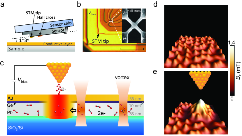
Results Sample design and vortex assembling. The experiments were performed by imaging vortices using scanning Hall probe microscopy (SHPM) which combines the non-invasive Hall imaging technique and an STM (Figs. 1a, b). The STM tip, typically used only to provide feedback to bring the Hall sensor in close proximity to the sample surface Bending , is here used as a local heating source. In the presence of tunnelling current, a pinning potential is created at the position of the tip due to the local suppression of the superconductivity. As a result, nearby vortices will be attracted to this region. However, once the tunnelling disappears by retracting the tip to a certain distance (200 nm), the heating effect is stopped and the accumulated vortices will finally relax into a triangular vortex lattice due to the repulsive interaction among them. To avoid this and to retain the topological defects after quenching, a sample with sufficiently strong pinning centers and weak vortex-vortex interactions is required.
The sample schematically shown in Fig. 1c is a multilayered structure of Pb/Ge/Au deposited on a SiO2/Si substrate (see Methods). The superconducting Pb film, which is characterized by relatively weak vortex-vortex interactions and a high density of quasi-homogeneously distributed pinning centers, is an ideal candidate to study the local heating effect. The pinning centers are created naturally during the sample preparation and can be considered as locations with a reduced electron mean free path Ge . The vortex-vortex interaction can be weakened by choosing a superconducting film with relatively small Ginzburg-Landau parameter . Therefore, a Pb film with thickness nm, nm and nm is used (Supplementary Figure 1, 2 and 3, and Supplementary Notes 1 and 2). In this case, once vortices are forced together, the attraction between pinning centers and vortices overcomes the repulsive interaction between vortices, so that a specific vortex configuration, formed in the course of fast hot-spot quenching, can be preserved.
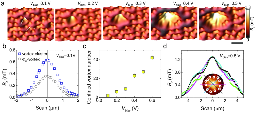
Figure 1d presents the vortex distribution SHPM image after performing field-cooling (FC) from above to 4.2 K. A disordered vortex lattice, homogeneously distributed in the scanned area, is observed. After applying a pulse of tunnelling voltage, followed by the Hall probe imaging, a vortex cluster is observed at the STM tip position. Since there is no multi-quantum vortex observed in our sample, we assume that the vortex cluster is composed of single quantum vortices (see Supplementary Note 4). Between the vortex cluster and the rest of individual vortices a vortex-free area is formed. Note that the positions of the vortices outside the cluster remain unchanged. This confirms that the impact of heating is local. The vortex cluster retains the same structure even after a few hours relaxation, suggesting that it is a relatively stable configuration. Similar results have been observed in three different samples. It has been reported that the STM tunnelling junction can reshape the topography of a material, generating defects at the tip position Baek . This possibility is ruled out since a disordered lattice is again observed in the same region after a subsequent FC procedure. The possibility of mechanically induced vortex attraction Nanoletter is also ruled out since, in our case, there is no direct contact between the STM tip and the sample.
Controlling the vortex cluster size. The size of the vortex clusters can be well controlled. Figure 2a shows a series of images measured after applying the pulse of tunnelling current at the same position under various bias voltages. It is clear that the size of the vortex cluster increases with increasing bias voltage. The smallest vortex cluster is observed at V, below which no vortex clustering can be seen. Figure 2b compares the magnetic field profiles through the centers of the vortex cluster observed at V and a single-quantum vortex. It is seen that the magnetic field at the center of the cluster is doubled as compared to a single-quantum vortex, suggesting that it contains two flux quanta (Supplementary Note 4). The number of trapped vortices as a function of the bias voltage is shown in Fig. 2c. The power dissipated in the sample is , with being the tunnelling current which is kept constant in our experiments. Correspondingly, the size of the region, where superconductivity is suppressed by local heating, is expected to increase with bias voltage. This accounts for the observed dependence in Fig. 2c.
One clear feature of the observed vortex clusters is that, instead of forming a disordered Abrikosov vortex lattice, clustered vortices are arranged into concentric ring-like structures. As demonstrated in Fig. 2d, the field profiles through the center of a vortex cluster are nearly symmetric with a peak at the cluster center. Such kind of ring-shaped vortex clusters, predicted by Shapiro et al Shapiro , might be attributed to the Kibble-Zurek (KZ) symmetry-breaking phase transition Kibble ; Zurek . When the tunnelling current is applied, the local area is heated up above , leading to the formation of a normal domain with homogeneous distribution of magnetic flux in this domain. After the heating is stopped by retracting the STM tip, the recovery of the superconductivity starts when the temperature front deviates from the order parameter front. The temperature front accelerates while the order parameter front, which presses the magnetic flux confined inside the shrinking normal region, decelerates, leading to an unstable normal domain ring area with and . As a result, vortices nucleate in this normal domain ring at the perimeter of the heated area and the hot spot looses part of its magnetic flux. The order parameter front then accelerates briefly, before the above-described dynamics repeat Shapiro ; Groger . With further decreasing temperature, natural pinning in the heated area becomes evident again, and the ring shaped vortex cluster is preserved even when the temperature of the whole area is far below . As far as we know, the ring-shaped vortex clusters have never been observed experimentally with single vortex resolution. The possible relation of our experiment to the KZ mechanism is further supported by the theoretical simulations, where vortex-antivortex pairs, as topological defects, appear from quenching the hot spot (Supplementary Figure 6, 7 and 8, and Supplementary Note 5). However, due to the short annihilation time, the stabilization of KZ vortices and antivortices have not been observed experimentally. Further experimental evidence is needed to clarify the mechanism, such as the relation of KZ vortices with quenching rate.
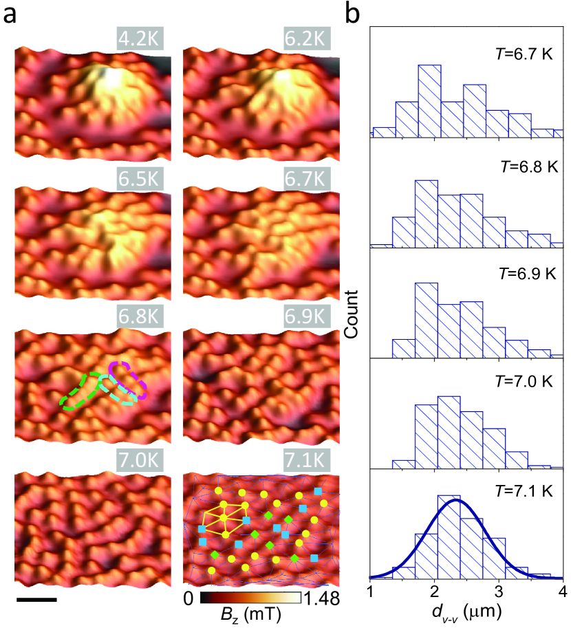
As mentioned above, the vortex clusters are preserved due to the naturally formed pinning centers. The pinning strength is weakened when approaching Fietz . Therefore, we expect a competition between pinning and vortex lattice elasticity with varying temperature. This also provides an opportunity to study the relaxation of local non-equilibrium configuration in a macroscopic system. Figure 3a displays the vortex cluster evolution with increasing temperature. When the vortex cluster is created at 4.2 K, it preserves the same geometry up to K (see Supplementary Figure 9), above which the pinning strength is considerably weakened as compared to the vortex-vortex interaction and the vortex cluster starts to disintegrate. We notice that the disintegration process starts from the interior of the vortex cluster, where vortex density is high, so that the vortex-vortex interaction is strong. At intermediate temperatures (e.g., K), vortices tend to form chains as highlighted by the dashed lines in Fig. 3a. Such vortex chains might be associated with the one-dimensional temperature-induced vortex motion as observed in the vortex lattice melting process Guillamon . Only at high enough temperature (e.g., K), vortex repulsion strongly dominates and a homogeneous distribution of vortices, corresponding to a weakly distorted Abrikosov lattice, is formed. Additional information about the vortex cluster disintegration process can be obtained by considering the nearest neighbor distance (NND) of vortices. As presented in Fig. 3b, the NND shows a broad distribution at low temperatures. At K, it can be well fitted by the Gaussian distribution (solid line). The observed peak position at m is consistent with the value expected for an Abrikosov triangular vortex lattice, m.
Theoretical simulations. The proposed scenario of vortex clustering is supported by the results of numerical simulations, based on the time-dependent Ginzburg-Landau (TDGL) formalism and the local heating model (Supplementary Figure 10 and Supplementary Note 6). The deviation of the local temperature from its equilibrium value in the absence of tunnelling current, , is represented as (see Fig. 4a), where the coefficient is proportional to the power dissipated by the tunnelling current, while the spatial temperature distribution is determined by material and geometric parameters of the sample. Using this temperature distribution to model the effect of a tunnelling current pulse, the TDGL calculations are performed for a m2 superconductor film with random pinning centers (Fig. 4b). Based on the used local heating model and the material parameters, the quenching time , corresponding to the thermal relaxation of the hot spot after switching off the tunneling current, is estimated to lie within the range of 1 to 10 ps for the initial radii of the normal domain in the hot spot from 1 to 3 m. These quenching-time values are comparable to the Ginzburg-Landau characteristic time in our sample, ps. The formation of vortex clusters, resulting from the simulated quenching process, and their stabilization due to vortex pinning typically occurs on the time scale to 100 ps. The vortex cluster formation time, compared with the short quenching time, clearly places the quenching process in the KZ regime.
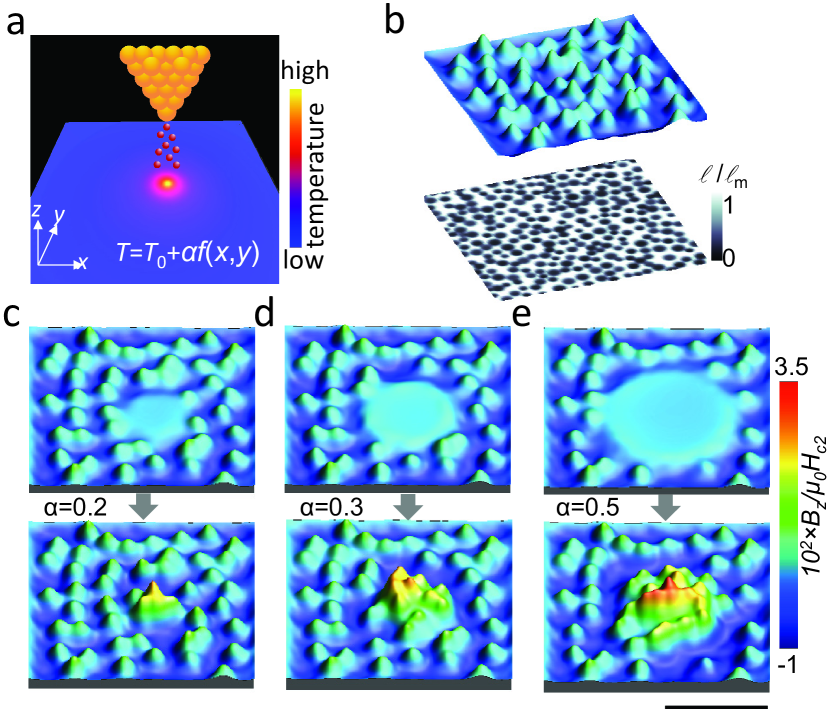
The simulation results are displayed in Figs. 4c to 4e for different values of the coefficient . The local heating, caused by tunnelling current, leads to the formation of a normal-state region in the vicinity of the STM tip. The normal region can be considered as a big pinning site, which is capable to accommodate a relatively large magnetic flux. This pinning site attracts and traps vortices from the surrounding superconducting area, where the temperature is elevated and the mobility of vortices is increased due to their weaker interaction with pinning centers. The magnetic flux trapped within the normal region increases with increasing . When the tunneling current is switched off and the local temperature relaxes to , the trapped flux transforms into a compact vortex cluster, which is stabilized by the pinning centers. Similarly to the experiment, the calculated vortex pattern demonstrates the appearance of vortex-depleted regions around the vortex cluster, which become more evident when increasing the intensity of local heating and the cluster size.
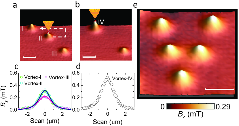
Manipulation of single-quantum vortices. The obtained results suggest that local heating with an STM tip can provide an efficient tool to arrange vortices in superconductors. Finally, we demonstrate the ability of using the STM tip to manipulate individual vortices (see also Supplementary Movie). This is an important extension of the pioneering work of Eigler Eigler from manipulating single atoms to manipulating single quantum vortices. To move a vortex, first, a tunneling junction is established by approaching the STM tip to the surface of the sample at 1 m away from the vortex center. A hot spot is generated and the vortex is attracted to the location of the hot spot. Then the STM tip is retracted and moved to the next position. By repeating the above process, we are able to drag the vortex to any position in the superconductor. As shown in Fig. 5a, a single quantum vortex (vortex II) can be moved along the path indicated by the dashed arrow to merge with vortex I, forming a vortex cluster (IV in Fig. 5b). We are also able to drag the vortex cluster as one object to a new position and then detach the two vortices by increasing the temperature (see Supplementary Figure 11). By using the local heating method demonstrated above, a pattern V, short for vortex, is arranged from -vortices as shown in Fig. 5e. Compared with other techniques, such as magnetic force microscopy Auslaender , that are used to manipulate individual vortices, the big advantage of our technique is that no magnetic field or transport current is needed.
Discussion In conclusion, we have shown that a controlled heating effect generated by the tunnelling current can be used to locally suppress superconductivity, with this area playing the role of a pinning center. We are able to tune to power of the nano heater simply by changing the bias voltage. Moreover, the tunnelling pulse applied through the STM tip enables dragging and manipulation of individual quantized vortices which may be used for the development of new fluxon-based devices. Our results demonstrate the utility of the local heating effect for characterizing and manipulating vortices in a superconductor. This new approach provides a lot of information which is of great interest for studying other systems, such as local and non-local phase transitions in superfluid, cosmology and many-particle systems.
Methods
Sample and experimental setup. The trilayer of Au/Ge/Pb was
prepared in two steps. First, to ensure a relatively small
of the sample, a 85 nm thick Pb film was deposited on a SiO2/Si
substrate using an ultra high vacuum ( Torr)
electron beam evaporator calibrated with a quartz monitor. The
substrate was cooled to 77 K by liquid nitrogen to ensure the
homogeneous growth of Pb. On top of Pb, a 10 nm thick Ge layer is
deposited to protect the sample surface from oxidation and also to
avoid any proximity effect between Pb and the subsequently deposited
conductive layer Kim . Second, the sample was transferred into
a sputtering machine, and a 35 nm thick Au layer was deposited to
cover the whole sample, playing the role of a conducting layer for
the tunnelling current of the STM tip. The thickness of Au yields a
smooth surface with a roughness less than 0.2 nm. The critical
temperature K is determined using local ac
susceptibility measurements. The pulse tunneling was applied by
controlling the bias voltage between the STM tip (Au) of a
commercial Hall probe as shown in Fig. 1b and the sample, which is
ground. In our experiments, the tunneling current is kept constant
( nA) through a PID protocol control. The magnetic field
distribution is recorded using the scanning Hall probe microscope
from Nanomagnetics in a lift-off mode (Supplementary Figure 12 and Supplementary Note 7).
First, the Hall sensor approaches the sample under the control of a
piezo until the tunneling current is established. Then the whole
sensor is retracted by 200 nm and the magnetic field distribution is
mapped. In all the measurements, the magnetic field is applied
perpendicularly to the sample surface. WSxM software is used to
process all SHPM images wsxm .
TDGL simulation. For a superconductor with pinning centers, which originate from a local reduction of the mean free path , the TDGL equation for the order parameter , normalized to 1, can be written in the form Ge
| (1) | |||||
where and are the scalar and vector potentials, respectively, and is the mean free path value outside the pinning centers. The relevant quantities are made dimensionless by expressing lengths in units of , time in units of , magnetic field in units of , and scalar potential in units of . Here, is the vacuum permeability, is the Ginzburg-Landau time, is the second critical field and is the coherence length at .
The vector potential , for which we choose the gauge , can be represented as . denotes the vector potential corresponding to the externally applied magnetic field , while describes the magnetic field induced by the currents , which flow in the superconductor:
| (2) |
Here, is the Ginzburg-Landau parameter and is the penetration depth at . The current density is expressed in units of with , the critical (depairing) current density of a thin wire or film. Integration in Eq. (2) is performed over the volume of the superconductor.
In general, the total current density contains both the superconducting and normal components: with
| (3) |
| (4) |
where is the normal-state conductivity, which is taken as in our units kato91 . The distribution of the scalar potential is determined from the condition
| (5) |
which reflects the continuity of currents in the superconductor. Both the and vanish when approaching (meta)stable states, which are of our main interest here.
Assuming that the thickness of the superconductor layer is sufficiently small, variations of the order parameter magnitude across the sample as well as currents in this direction can be neglected and Eq. (1) becomes effectively two-dimensional. This equation together with Eqs. (2) and (5) are solved self-consistently following the numerical approach described in Ref. silhanek2011local .
Data availability. All relevant data are available from the corresponding author.
References
- (1) Blatter, G., Feigelman, M. V., Geshkenbein, V. B., Larkin, A. I. & Vinokur, V. M. Vortices in high-temperature superconductors. Rev. Mod. Phys. 66, 1125-1388 (1994).
- (2) Liang, R., Bonn, D. A. & Hardy, W. N. Evaluation of CuO2 plane hole doping in YBa2Cu3O6+x single crystals. Phys. Rev. B 73, 180505 (2006).
- (3) Bezryadin, A., Ovchinnikov, Y. N. & Pannetier, B. Nucleation of vortices inside open and blind microholes. Phys. Rev. B 53, 8553-8560 (1996). Supercond. Sci. Technol. 27, 063001 (2014).
- (4) Moshchalkov, V. V. Pinning by an antidot lattice: the problem of the op- timum antidot size. Phys. Rev. B 57, 3615-3622 (1998).
- (5) de Souza Silva, C. C., Van de Vondel, J., Morelle, M. & Moshchalkov, V. V. Controlled multiple reversals of a ratchet effect. Nature 440, 651-654 (2006).
- (6) Auslaender, O. M. et al. Mechanics of individual isolated vortices in a cuprate superconductor. Nature Phys. 5, 35-39 (2009).
- (7) Albrecht, J. Dramatic Role of Critical Current Anisotropy on Flux Avalanches in MgB2 Films. Phys. Rev. Lett. 98, 117001 (2007).
- (8) Grigorenko, A., Bending, S., Tamegai, T., Ooi, S. &Henini, M. A one-dimensional chain state of vortex matter. Nature 414, 728-731 (2001).
- (9) Suderow, H., Guillamon, I., Rodrigo, J. G. & Vieira, S. Imaging superconducting vortex cores and lattices with a scanning tunnelling microscope. Supercond. Sci. Technol. 27, 40-47 (2014).
- (10) Roditchev, D. Direct observation of Josephson vortex cores. Nature Phys. 11, 332-337 (2015).
- (11) Shan, L. Observation of ordered vortices with Andreev bound states in Ba0.6K0.4Fe2As2. Nature Phys. 4, 325-331 (2011).
- (12) Sandhu, A. Scanning tunnelling microscopy: probing superconductivity at the nanoscale. Nature Nanotechnology 4, 142 (2009).
- (13) Wong, D. Characterization and manipulation of individual defects in insulating hexagonal boron nitride using scanning tunnelling microscopy. Nature Nanotech. 10, 949-953 (2015).
- (14) Butler, C. J. Mapping polarization induced surface band bending on the Rashba semiconductor BiTeI. Nature Commun. 5, 4066 (2014).
- (15) Zhao, L. Common electronic origin of superconductivity in (Li,Fe)OHFeSe bulk superconductor and single-layer FeSe/SrTiO3 films. Nature Commun. 7, 10608 (2016).
- (16) Eigler, D. M. & Schweizer, E. K. Positioning single atoms with a scanning tunnelling microscope. Nature 344, 524-526 (1990).
- (17) Eigler, D. M., Lutz, C. P. & Rudge, W. E. An atomic switch realized with the scanning tunnelling microscope. Nature 352, 600-603 (1991).
- (18) Kalff, F. E. A kilobyte rewritable atomic memory. Nature Nanotech. doi:10.1038/nnano.2016.131 (2016).
- (19) Tanaka, H. & Kawai, T. Partial sequencing of a single DNA molecule with a scanning tunnelling microscope. Nature Nanotech. 4, 518-522 (2009).
- (20) Guillamon, I. Direct observation of melting in a 2-D superconducting vortex lattice. Nature Phys. 5, 651-655 (2009).
- (21) Song, C.-L. Direct observation of nodes and twofold symmetry in FeSe superconductor. Science 332, 1410-1413 (2011).
- (22) Guillanmon, I. Enhancement of long-range correlations in a 2D vortex lattice by an incommensurate 1D disorder potential. Nature Phys. 10, 851-856 (2014).
- (23) Golod, T., Iovan, A. & Krasnov, V. M. Single Abrikosov vortices as quantized information bits. Nature Commun. 6 8628 (2015).
- (24) Miyahara, K., Mukaida, M. & Hohkawa, K. Abrikosov vortex memory. Appl. Phys. Lett. 47, 754-756 (1985).
- (25) Bending, S. J. Local magnetic probes of superconductors. Adv. Phys. 48, 449-535 (1999).
- (26) Ge, J.-Y., Gutierrez, J., Gladilin, V. N., Devreese, J. T. & Moshchalkov, V. V. Bound vortex dipoles generated at pinning centers by Meissner current. Nature Commun. 6, 6573 (2015).
- (27) Baek, H. Creating nanostructured superconductors on demand by local current annealing. Phys. Rev. B 92, 094510 (2015).
- (28) Kremen, A., Wissberg, S., Haham, N., Persky, E., Frenkel, Y. & Kalisky, B. Mechanical control of individual superconducting vortices. Nano Lett. 16, 1626-1630 (2016).
- (29) Shapiro, I., Pechenik, E. & Shapiro, Y. Recovery of superconductivity in a quenched mesoscopic domain. Phys. Rev. B 63, 184520 (2001).
- (30) Kibble, T. W. B. Topology of cosmic domains and strings. J. Phys. A 9, 1387-1398 (1986).
- (31) Zurek, W. H. Cosmological experiments in superfluid helium. Nature 317, 505-508 (1985).
- (32) Groger, A., Bohm, A., Beyer, U., Shapiro, B. Y., Shapiro, I., & Wyder, P. Ring-shaped vortex domain in type-II superconductors. Phys. Rev. Lett. 90, 237004 (2003).
- (33) Fietz, W. A. & Webb, W. W. Hysteresis in superconducting alloy temperature and field dependence of dislocation pinning in niobium alloys. Phys. Rev. 178, 657 (1969).
- (34) Kim, J., Chua, V., Fiete, G. A., Nam, H., MacDonald, A. H. & Shih, C.-K. Visualization of geometric influences on proximity effects in heterogeneous superconductor thin films. Nature Phys. 8, 464-469 (2012).
- (35) Horcas, I. WSXM: A software for scanning probe microscopy and a tool for nanotechnology. Rev. Sci. Instrum. 78, 013705 (2007).
- (36) Kato, R., Enomoto & Y., Maekawa, S., Effects of the surface boundary on the magnetization process in type-II superconductors. Phys. Rev. B 47, 8016-8024 (1993).
- (37) Silhanek, A. V. Local probing of the vortex–antivortex dynamics in superconductor/ferromagnet hybrid structures. Supercond. Sci. Technol. 24, 024007-024015 (2011).
Acknowledgements
We acknowledge the support from the Methusalem funding by the
Flemish government, the Flemish Science Foundation (FWO) and the
MP1201 COST action. J.T. also acknowledges support from the Research
Council of Antwerp University (BOF). Y.Z. and C.X. acknowledge the
National Natural Science Foundation of China (No. 11421062), the
National Key Project of Magneto-Constrained Fusion Energy
Development Program (No. 2013GB110002) and the CSC program.
Author contributions
J.Y.G. and C.X. made the sample. J.Y.G. performed the SHPM measurements.
V.G., J.T. and J.T.D. did the simulations. J.Y.G., V.G. and V.V.M.
wrote the manuscript. All authors contributed to the discussion and
analysis. V.V.M. coordinated the whole work.
Competing financial interests
The authors declare no competing financial interests.