On the Transport Capability of LAN Cables in All-Analog MIMO-RoC Fronthaul
Abstract
Centralized Radio Access Network (C-RAN) architecture is the only viable solution to handle the complex interference scenario generated by massive antennas and small cells deployment as required by next generation (5G) mobile networks. In conventional C-RAN, the fronthaul links used to exchange the signal between Base Band Units (BBUs) and Remote Antenna Units (RAUs) are based on digital baseband (BB) signals over optical fibers due to the huge bandwidth required. In this paper we evaluate the transport capability of copper-based all-analog fronthaul architecture called Radio over Copper (RoC) that leverages on the pre-existing LAN cables that are already deployed in buildings and enterprises. In particular, the main contribution of the paper is to evaluate the number of independent BB signals for multiple antennas system that can be transported over multi-pair Cat-5/6/7 cables under a predefined fronthauling transparency condition in terms of maximum BB signal degradation. The MIMO-RoC proves to be a complementary solution to optical fiber for the last 200m toward the RAUs, mostly to reuse the existing LAN cables and to power-supply the RAUs over the same cable.
Index Terms:
Radio over Cable, Massive MIMO, C-RAN.I Introduction
The radio access network (RAN) paradigm is completely changing in next generation (5G and beyond) mobile systems due to the ever-growing traffic demand, calling for the fulfillment of strict requirements in terms of throughput, mobility and latency. Pervasive deployment of a large number of antennas appears to be the only viable solution to meet such requirements [1], though introducing complicated interference scenarios. In this context, Centralized RAN (C-RAN) [2] addresses the challenging interference management task through centralized processing to handle a massive number of antennas/cells, taking benefits from their mutual cooperation for interference mitigation. Key enabler for C-RAN is the co-location of baseband units (BBUs) in so-called BBU pools, that allows centralized processing providing remarkable benefits in terms of programmability, scalability and cost reduction. The antennas, with all the radio-frequency (RF) functionalities, are hosted at the remote antenna units (RAUs) while modulation/demodulation and precoding are performed at the BBUs. The fronthaul link between RAUs and BBUs is conventionally designed to exchange digital in-phase and quadrature (I/Q) signals streaming according to the CPRI protocol [3], demanding analog/digital conversion at the RAU.
The expected increase in RF signal bandwidth and the massive number of antennas call into question the effectiveness of this digital I/Q streaming, that would introduce a bandwidth expansion of RF signals over fronthauling that can be as severe as 30x. Compression of digital I/Q signals [4] or RAN functional splits [5] are not enough for bandwidth reduction. In all-analog fronthauling the RAUs directly relay the analog BB signals (possibly after frequency translation) to/from the BBUs (or any midway equipment) thus avoiding any bandwidth expansion, minimizing the latency (that is just the propagation) and hardware cost while improving energy efficiency [6, 7, 8]. Analog radio over fiber (RoF) provides an effective example of analog fronthauling, due to its capability to carry several Gbit/s in terms of equivalent data-rate [8, 7]. However, RoF infrastructure would require the deployment of a large-scale and pervasive fiber optic infrastructure whose cost can be excessive. Even if RoF could be based on passive optical networks (PON), the RAUs still need the power supply for optical sources and electronics, and this could make the economical benefits of using PON questionable, mostly for the last 100-200m of fronthauling. These issues can be dealt with by a hybrid fiber-cable architecture (Fig. 1), as foreseen in [9].
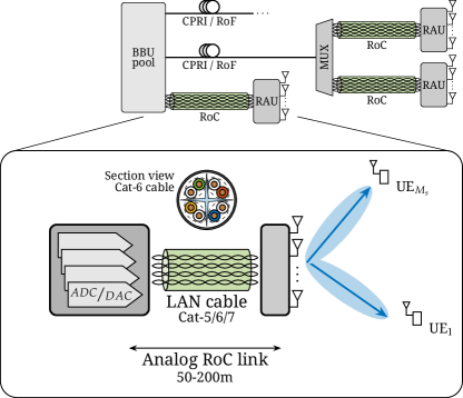
Radio over Copper (RoC) [6, 10] is a complementary/alternative technology for fronthauling that makes use of LAN cables which are nowadays already largely deployed in buildings and enterprises, thus cutting the costs of the deployment of a brand-new network infrastructure, mostly if considering indoor coverage. Here we analyze the potential of RoC provided by multi-pair LAN cables containing 4 twisted pairs bounded together to provide at least 4 separated cable-pairs (or space) channels with a bandwidth of up to 1GHz/pair (depending on the cable type). Cat-5/6/7 cables enable the design of all-analog and low-cost fronthauling (at least for the last 100-200m) capable of supporting a large number of independent radio access channels (possibly corresponding to different radio access technologies, RATs) or a massive number of antennas at each RAU. The equivalent data-rate over copper-cable systems is large enough to make RoC extend fiber optics coverage.
Differently from [6, 11], where each BBU-RAU connection is provided by a single twisted pair, the use of multi-pair LAN cables introduces an additional multiplexing dimension for the wired fronthaul channel as at least 4 mutually interfering channels are available for each frequency band (more channels if considering the phantom-modes of cables). The overall channel between the BBU and the end-user is therefore modeled as the cascade of a MIMO radio channel and a MIMO cable channel, where the signal to/from each antenna needs to be properly mapped onto the available cable-frequency resources within the LAN cable, defined here as space-frequency domain of the cable. In this paper the Cat-5/6/7 cables characteristics are revised to delineate the link budget for the cascade of air and copper links. The link-budget helps to define the maximum number of independent RAT channels (or independent antennas in every RAU) that can be allocated on different cables/frequency bands taking into account the maximum power spectral density over cables to avoid extra-cable interference.
Contributions: The contributions of this paper are three-fold: i) we propose an all-analog MIMO-RoC fronthauling based on LAN cables supporting massive numbers of antennas over independent copper-links, ii) we show the potential of Cat-5/6/7 cables by evaluating the number of independent RAT channels that different cable types and lengths can accommodate without any air-link degradation, iii) we propose a dynamic power allocation for MIMO-RoC that enables to minimize any cable cross-talk.
Notation: Bold upper- and lower-case letters describe matrices and column vectors. denotes the ij-th element of matrix Letters refer to real and complex numbers, respectively. We denote matrix inversion, transposition and conjugate transposition as and matrix is an identity matrix of appropriate size.
Organization: Section II introduces the system model for the radio scenario and the MIMO-RoC fronthauling, considering the combined effects of air and cable interference. LAN cable characteristics are summarized in Section III, while in Section IV power resource allocation is presented. Numerical results are in Section V and concluding remarks and future works are highlighted in Section VI.
II System Model and Parameters
The system model for the proposed MIMO-RoC fronthauling is shown in Fig. 2 for uplink transmission (downlink would be similar, not covered here), where antennas at the RAU are connected to the BBU by a LAN cable with twisted pairs to serve users. To simplify the reasoning here, users are equipped with one antenna each, but any generalization is straightforward. Each RAU relays towards the BBU (or any other mid-way equipment) the analog signals received from the users after a proper analog-to-analog (A/A) conversion consisting in frequency downconversion of RF signal to match the cable frequency band and an amplifier to be detailed later.
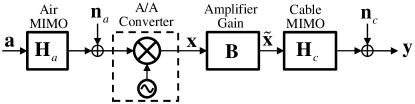
The signal received at the antenna array (after downconversion) is modeled as flat-fading (e.g., it corresponds to one subcarrier of OFDM/OFDMA modulation)
| (1) |
where is the air-link channel matrix from the users to the antennas, is the users signal, and is the air-link noise at the antenna array with power . The signal received at the BBU after A/A is
| (2) |
where is the space-frequency MIMO cable channel accounting for the frequency-dependent insertion loss (IL, on the main diagonal elements ) and for the frequency-dependent far-end crosstalk (FEXT, on the off-diagonal terms ). The signals are channelized in frequency division multiplexing (FDM) over cable bands with pairs/ea., the cable channel is block-diagonal to guarantee the orthogonality over the cable-bands:
| (3) |
Cable channel at the -th frequency band contains the insertion loss and crosstalk elements for the spatial cable channels. The total bandwidth available over the space-frequency cable channels should be for a given signal to interference plus noise ratio (SINR) degradation of the cable (Sect. III-B).
In order to cope with cable crosstalk without any digital signal processing, the only degrees of freedom are the antenna mapping onto cable and the design of the amplification for each copper/frequency-link. is the amplifier gain matrix that is designed to minimize the cable crosstalk effect by adjusting the transmitted power over each space-frequency cable channel as detailed in Sect.IV. The additive noise introduced by the cable is and (2) becomes
| (4) |
where contains the signals transmitted from RAU to BBU over the twisted pairs and cable frequency bands.
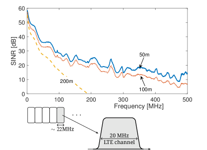
For LAN cables , and the total bandwidth depends on cable length and type. Even if their bandwidth can be as high as approx. 1 GHz, here the analysis is only for the first 500 MHz for the availability of experimental measurements and models. Moreover, the analysis is for multiple antennas LTE system with 20-MHz bandwidth that uses a global bandwidth of 22 MHz comprehensive of 10% of guard band overhead for FDM over cables. Even if the cable channels are frequency-dependent, for the sake of simplicity in numerical analysis, the cable channel matrix is approximated as constant within each 22-MHz band.
III LAN Cables for MIMO-RoC
The fronthaul capacity of the RoC architecture in [6] can be greatly enhanced through MIMO-RoC, that efficiently exploits cables with multiple twisted pairs as the 4-pairs of LAN cables detailed below.
III-A Cables Characteristic
Standard LAN cables (Cat-5/6/7) are considered here for MIMO-RoC. Cat-5 cables are unshielded twisted pair (UTP) cables, commonly deployed for computer networks (e.g., Gigabit Ethernet) and their performances are mostly affected by the system noise. Cat-6 cables are high-grade UTP cables with additional foil underneath the cable jacket, in which better noise and interference immunity is achieved by increasing the twists density ( twists/cm for Cat-6, compared to 1.5 twists/cm for Cat-5). Cat-7 cables offer lower signal attenuation and reduced intra-cable interference through extensive shielding and foiling over each individual twisted pair, and therefore can be used in a noisy environment, or to remarkably increase the transport capability with respect to Cat-5 cables.
The transmission bandwidth over each copper link is typically considered up to 212 MHz for 100-m cables (e.g., G.fast as next generation DSL), but it can reach as much as 1 GHz for LAN cables, especially for shorter distances ( m). Cable lengths can vary in a range between few meters up to several hundreds of meters, but higher insertion losses are associated with longer cables, thus reducing the practically available transmission bandwidth as shown in Fig. 3. The analysis is limited here to 50-m, 100-m and 200-m LAN cables over maximum bandwidth of 500 MHz (limit due to the reliability of available measurements). Notice that, even thought the total available bandwidth of each pair is , the useful bandwidth for signal transmission is reduced for the joint effect of cable attenuation and crosstalk and .
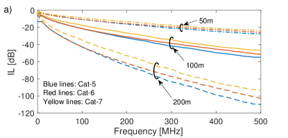
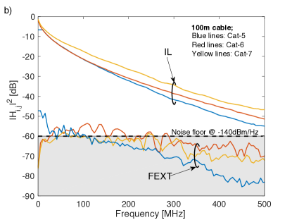
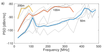
Fig.3 shows the characteristics of the 3 categories of cables in terms of average (over pairs) insertion loss versus frequency for varying cable length (Fig.3a), and in terms of average IL and FEXT for 100-m length for varying Cat-type (Fig.3b). In Fig.3b the noise-floor is highlighted assuming that its power spectral density (typ. is dBm/Hz) is normalized to the maximum spectral mask of signal ( dBm/Hz). Cables have a low-pass characteristic that increases with cable length as shown in Fig.3a. For the scope of having a transparent RoC, it is meaningful to derive from Fig.3 the SINR versus frequency that is illustrated in Fig.4 for Cat-6 cable and varying cable lengths (50, 100 and 200 m). It can be noticed from Fig.4 that in case of longer cables (i.e., 200 m) the noise dominates over FEXT limiting its usage up to 200 MHz.
III-B Cable Resources Analysis
In the proposed MIMO-RoC fronthauling architecture, the signal from each antenna is mapped over one of the different 22-MHz bands of LAN cable, as shown in Fig.4. Given the bandwidth of each air-link (that in the numerical analysis is MHz), the bandwidth to transport over cable the overall antennas is , hence the cable transport capability must be
| (5) |
where is the useful transmission bandwidth on the -th twisted pair of the in a cable subject to a minimal SINR level induced by the cable from Fig.4. From (5), and thus
| (6) |
is the maximum number of independent RAT channels (antennas) that can be allocated onto a LAN cable.
IV Power Allocation in MIMO-RoC
The main limitation in LAN cables is the crosstalk among the twisted pairs. Crosstalk cancellation is the obvious solution to maximize the throughput over the copper, but it requires the digitalization and the corresponding digital signal processing at the A/A converter, that is too energy and latency consuming compared to the all-analog relaying (not to mention the cost). The aim of the power allocation in MIMO-RoC is to optimize the power of the transmit signal over the space-frequency copper channels such that the crosstalk among the cable pairs is minimized. Since copper channel gains (IL and FEXT) are time-invariant compared to the air-links, the power allosubcation problem consists in optimizing the gains of the diagonal matrix that scales the power of the input signal prior to transmission over the cable. This can be solved by adapting the optimum spectrum balancing (OSB) algorithm [12, 13] to RoC.
The SINR at BBU follows from (4) and it can be represented for line and -th subcarrier as
| (7) |
where is the channel gain from cable pair towards (), and is the transmit signal power over the -th cable pair at -th frequency band such that
| (8) |
The power is optimized to minimize the crosstalk toward the other lines (), and the optimization problem for all the cable pairs () and sub-carriers () can be stated as
| s.t. | ||||
| (9) |
where is the throughput of the -th pair by summing the contributions from sub-carriers with frequency spacing MHz (as in Fig. 4):
| (10) |
is the sum power of all the sub carriers for line , and it is constrained by the maximum transmit power of the cable amplifier . The maximum transmit power per subcarrier is also constrained to . The required transmit power on -th subcarrier for all the cable pairs is [12, 13]
| (11) |
where
| (12) | ||||
| (13) | ||||
| (16) |
and the required SINR in (13) are selected iteratively for different M-QAM constellations to guarantee that power allocation is positive valued. The numerical values here are derived from the LTE specifications [14]. The spectrum balancing algorithm in [12] provides an efficient solution for the optimization problem in (9), in the form of an amplifier gain matrix . Such matrix is block diagonal as in (3): and the amplifier gain matrix for -th subcarrier is
| (17) |
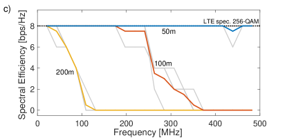
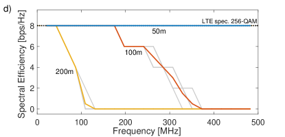
To comply with the air-link specification for LTE, the spectral efficiency is upper-limited to 8 bps/Hz, corresponding to the maximum constellation of the evolution of LTE that supports up to 256-QAM.
V Numerical Results
Simulation results for different cable types and lengths, based on the input parameters summarized in Table I, are presented here to show the effectiveness of the proposed fronthauling architecture. In particular, the number of independent 20-MHz LTE signals (assumed to be equal to the number of antennas ) available on the cable channel is evaluated by considering the modulation parameters from LTE specifications [14].
![[Uncaptioned image]](/html/1702.03911/assets/Figures/Tables/Tab1_new.jpg)
The copper bandwidth is limited here up to 500 MHz even if the usage can be expanded up to 1 GHz and beyond, as foreseen for future broadband access networks [9].
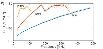
The results of OSB as defined in (9) are shown in Fig. 5 for a Cat-5 cable, and reported in Tables II, III for Cat-5/6/7. In order to compare the OSB for RoC with digital pre-compensation of FEXT at RAU, the performance of conventional Tomlinson-Harashima precoding (THP) for FEXT compensation in multi-pair copper cables [15] is shown as reference in Fig. 5b, d, and in Table III. In particular, the averaged (over the pairs) OSB transmit powers over the 22-MHz bins are in the upper part of Fig. 5, while the powers for each of the 4 twisted pairs are in gray lines. The corresponding spectral efficiency that corresponds to the M-QAM modulations of LTE according to the specifications is in the lower part of the same figure.
![[Uncaptioned image]](/html/1702.03911/assets/Figures/Tables/Tab3.png)
The power required for any given modulation scheme increases with cable impairments, and consequently with frequency and length.
![[Uncaptioned image]](/html/1702.03911/assets/Figures/Tables/Tab4.png)
We observe that the 256-QAM (spectral efficiency of 8 bps/Hz) is guaranteed for the entire 500-MHz bandwidth when using the 50-m cables. Increasing the cable length the 256-QAM requirements can be fulfilled over a reduced bandwidth up to approx. 175 MHz and 25 MHz for 100 and 200-m cables. Comparison with digital FEXT compensation shows a modest improvement compared to the cost. The maximum useful bandwidth for transmission on each pair (, second to last column in Tables II, III) is obtained from Fig. 5c,d as the spectrum portion corresponding to non-zero spectral efficiency and the total number of antennas is computed for the useful transmission bandwidth as in (6). It is to be noticed that the average sum power per line is always lower than 4dBm, that is the limit of commercially available power driver for twisted-pairs. As expected, the maximum throughput is achieved by Cat-7 cables, due to its higher FEXT protection capabilities.
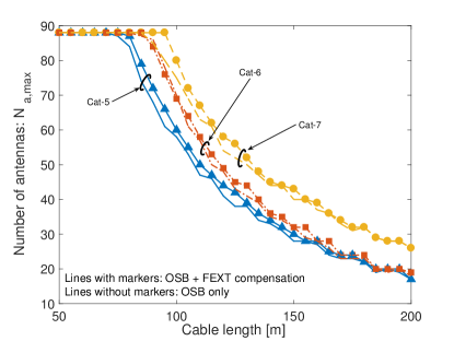
The total number of allocable independent 20-MHz LTE channels that corresponds to the number of antennas versus cable length is in Fig. 6 for all cable types and considering also the impact of FEXT processing at the RAU as design parameter. Up to around 75 m, any cable (regardless the use of FEXT compensation) allows to serve the maximum number of antennas compatible with 500-MHz bandwidth that is (i.e., 22 LTE channels on each pair), which is limited by the 500-MHz bandwidth for reliable cable measurements. Distance of 100 m on a LAN cable is considered as a reference, and at least 55 independent LTE channels (or independent antennas) can be transported using MIMO-RoC on Cat-5, thus proving the effectiveness of MIMO-RoC fronthauling for the last 100 m of the C-RAN architecture. It is important to notice that the beneficial effects of crosstalk compensation are modest, and can be appreciated only for lower cable lengths where the interference dominates over noise. This is a strong argument in favor of the usage of all-analog processing of judicious power allocation in all-analog MIMO-RoC fronthauling to minimize any latency of the I/Q signal transport.
VI Concluding Remarks
In this paper we consider the implementation of fully-analog fronthauling based on the RoC paradigm that is based on the use of LAN cables, already largely deployed in buildings and enterprises. In particular, we prove the great potential provided by multi-pair LAN cables, evaluated in terms of number of antennas that can be served for different cable lengths and types. By numerical evaluation, we prove that in a 50-m Cat-5 cable the maximum number of antennas (or 20-MHz LTE channels) is 88, and this value is limited by the cable bandwidth of 500 MHz considered here. In particular, at least 60 antennas can be served by a cable of practical length (100 m), thus enabling the design of MIMO-RoC fronthauling to serve a RAU with a large number of antenna elements. Pushing cable bandwidth up to 1 GHz and beyond, it can be shown that the number of allocable RAT channels rises up to approx 120. The proposed radio-MIMO over cable-MIMO allows the joint exploitation of space and frequency multiplexing on both cable (multiple pairs) and air (multiple antennas). Hence a further degree of freedom in the design of the proposed architecture is given by the mapping between the space-frequency channels defined by antennas and radio spectrum onto the cable-pairs and cable spectrum. This promising activity is planned as future work, together with a thorough cost-benefit comparison with RoF.
References
- [1] F. Boccardi et al., “Five disruptive technology directions for 5G,” IEEE Communications Magazine, vol. 52, pp. 74–80, February 2014.
- [2] A. Checko et al., “Cloud RAN for Mobile Networks - A Technology Overview,” IEEE Communications Surveys Tutorials, vol. 17, no. 1, pp. 405–426, 2015.
- [3] “CPRI Specifications V.6.1 (2014-07-01),” September 2014.
- [4] S. Nanba and A. Agata, “A New IQ Data Compression Scheme for Front-haul Link in Centralized RAN,” in IEEE PIMRC, Sept. 2013.
- [5] J. Bartelt et al., “Fronthaul and Backhaul Requirements of Flexibly Centralized Radio Access Networks,” IEEE Wireless Communications, Oct. 2015.
- [6] J. Gambini and U. Spagnolini, “Wireless over cable for femtocell systems,” IEEE Communications Magazine, vol. 51, pp. 178–185, May 2013.
- [7] D.Wake et al., “Radio Over Fiber Link Design for Next Generation Wireless Systems,” Journal of Lightwave Technology, vol. 28, no. 16, pp. 2456–2464, 2010.
- [8] H. S. Chung et al., “Design of RoF based Mobile Fronthaul Link with Multi-IF Carrier for LTE/LTE-A Signal Transmission,” in IEEE APMP, 2014.
- [9] F. Effenberger, “Future Broadband Access Networks,” Proceedings of the IEEE, vol. 104, pp. 2078–2081, November 2016.
- [10] C. Lu et al., “Connecting the dots: small cells shape up for high-performance indoor radio,” Ericsson Rev., vol. 91, pp. 38–45, Dec. 2014.
- [11] E. Medeiros et al., “Crosstalk Mitigation for LTE-Over-Copper in Downlink Direction,” IEEE Communications Letters, vol. 20, pp. 1425–1428, July 2016.
- [12] R. Cendrillon et al., “Optimal multiuser spectrum balancing for digital subscriber lines,” IEEE Transactions on Communications, vol. 54, no. 5, pp. 922–933, 2006.
- [13] P. Tsiaflakis et al., “A low complexity optimal spectrum balancing algorithm for digital subscriber lines,” Signal Processing, vol. 87, no. 7, pp. 1735–1753, 2007.
- [14] J. Wannstrom, “LTE-advanced,” Third Generation Partnership Project (3GPP), 2012.
- [15] M. Hekrdla et al., “Ordered Tomlinson-Harashima Precoding in G.fast Downstream,” in 2015 IEEE GLOBECOM, pp. 1–6, IEEE, 2015.