Chiral Optical Tamm States: Temporal Coupled-Mode Theory
Abstract
The chiral optical Tamm state (COTS) is a special localized state at the interface of a handedness-preserving mirror and a structurally chiral medium such as a cholesteric liquid crystal or a chiral sculptured thin film. The spectral behavior of COTS, observed as reflection resonances, is described by the temporal coupled-mode theory. Mode coupling is different for two circular light polarizations because COTS has a helix structure replicating that of the cholesteric. The mode coupling for co-handed circularly polarized light exponentially attenuates with the cholesteric layer thickness since the COTS frequency falls into the stop band. Cross-handed circularly polarized light freely goes through the cholesteric layer and can excite COTS when reflected from the handedness-preserving mirror. The coupling in this case is proportional to anisotropy of the cholesteric and theoretically it is only anisotropy of magnetic permittivity that can ultimately cancel this coupling. These two couplings being equal results in a polarization crossover (the Kopp–Genack effect) for which a linear polarization is optimal to excite COTS. The corresponding cholesteric thickness and scattering matrix for COTS are generally described by simple expressions.
Introduction
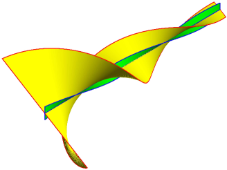
Matter tends to order thus forming crystals. Orientation alignment is the preferred order in liquid crystals. Due to its cyclic nature, it can generate an echo of a translational order in chiral superlattices of cholesteric liquid crystal. Under diffraction, in cholesteric crystals the helical structure of the matter is rendered to the field because the co-handed circularly polarized wave diffracts (Fig. 1) while the cross-handed circularly polarized wave travels virtually unaffected. This phenomenon is referred to as selective reflection Belyakov (1992) or, alternatively, Bragg circular diffraction for electromagnetic and acoustic waves Faryad and Lakhtakia (2014).
The results obtained are readily generalized for any material with a helix-like response, including widely tunable heliconical structures Xiang et al. (2015). The selective reflection obstructs observation of localized states when the order at the interface or at the structural defect is disturbed. This is paid off by a simpler description of the states, which is an advantage offered by smooth helix symmetry Belyakov (1992); Avendaño et al. (2005) as opposed to discrete translational symmetry of crystals. The structural defect is conventionally represented as a cavity confined by mirrors, where the role of mirrors is played by the Bragg grating. This counterpart of a Fabry–Perot resonator possesses a number of defect modes. The latters are localized optical states normally corresponding to the whole number of halfwaves accommodated in the cavity. There are a number of distinctive polarization features Haus and Shank (1976); Lakhtakia and McCall (1999); Yang et al. (1999); Shabanov et al. (2004); Gevorgyan (2006); Belyakov and Semenov (2011); Kiselev and Chigrinov (2014) associated with the chiral defect applications Faryad and Lakhtakia (2014); Hsiao et al. (2014); Rodarte et al. (2015); Lin et al. (2015); Kesaev et al. (2016), among which the twist defect, lacking an intermediate layer and having zero thickness, is the most prominent Hodgkinson et al. (2000); Kopp and Genack (2002). Strict theoretical Oldano et al. (2003); Becchi et al. (2004); Avendaño et al. (2005); Schmidtke and Stille (2003) and experimental Hodgkinson et al. (2000); Schmidtke et al. (2003); Ozaki et al. (2003); Shibaev et al. (2002) studies of the phenomenon gave rise to a discussion on polarization and relaxation time of the localized state Oldano (2003); Kopp and Genack (2003). Theoretically, infinite relaxation time is only possible if there is anisotropy of magnetic permittivity Avendaño et al. (2005); Gevorgyan and Rafayelyan (2013). Otherwise it appears impossible to simultaneously match electric and magnetic field strengths at the interface. Note that infinitely increasing the cholesteric thickness does not provide infinite improvement of the quality factor. The quality factor saturates with increasing cholesteric thickness and circular polarization of the transmitted light changes from co-handed to cross-handed. This polarization crossover Kopp and Genack (2002) has been called the Kopp–Genack effect McCall et al. (2015). Unlike the Fabry–Perot resonator, the twist defect generates a single localized state. The spatial field distribution curve in this case has no flat top and consists of two waves exponentially descending in opposite directions. This resembles a surface wave with the only difference that for the twist defect there is no limitation on the angle of incidence of the excitation wave, and surface waves at the cholesteric-isotropic dielectric interface are only observed at the angles ensuring complete internal reflection Belyakov and Shilina (1992).
There exists a surface wave beyond the restriction of complete internal reflection. It is known as an optical Tamm state (OTS) Kavokin et al. (2005); Vinogradov et al. (2010); Iorsh et al. (2012); Afinogenov et al. (2013); Auguié et al. (2015); Chang et al. (2015); Yang et al. (2016), which is similar to the Tamm state of electrons at the superlattice interface. The dispersion of OTS lies outside the light cone given by Kaliteevski et al. (2007). Such a state can be excited even perpendicular to the surface without energy transfer along the surface, which is an advantage for various applications. A question naturally arises if there is an OTS at the cholesteric-metal interface when the light is incident perpendicularly. When dealing with this problem, one should bear in mind two things: first, semitransparence of the cholesteric due to the circular Bragg diffraction and, second, polarization change caused by alternating circular polarizations, namely: reflection from cholesteric does not change the handedness of circular polarization whereas reflection from metal does Abdulhalim (2006). This alternation acts like traffic lights: a co-handed circular polarized wave is not allowed to go through the cholesteric until after it has been twice reflected from the metal Timofeev et al. (2013). The polarization match at the interface between chiral and nonchiral mirrors can be achieved by adding an extra anisotropic layer. This layer produces a set of localized states with nontrivial polarization properties Vetrov et al. (2014, 2016); Pyatnov et al. (2016). Various combinations involving two mirrors have been extensively studied and offered for practical applications Zhuang and Patel (1999); Abdulhalim (2006), including less-than-one-pitch chiral layer Isaacs et al. (2014); Hsiao et al. (2011); Timofeev et al. (2012); Timofeev and Vetrov (2016); Gunyakov et al. (2016); Huang et al. (2016). The closer to the mirror, the higher the energy density of the states may become, but still the states are not localized at surface but within the bulk of the extra layer. It is possible to do without an extra layer provided a handedness-preserving mirror (HPM) is used Plum and Zheludev (2015); Fedotov et al. (2005); Kopp and Genack (2003); Rudakova et al. (2017). HPM maintains not only the handedness but also the ellipticity magnitude upon reflection, therefore, such a mirror is also referred to as a polarization-preserving anisotropic mirror Rudakova et al. (2017). Also HPM can be defined as a reflector with the effect of half-wave phase plate Ding et al. (2015). A localized state at the HPM/choleric interface was described in the low anisotropy approximation of cholesteric crystal and was called a chiral optical Tamm state (COTS) Timofeev and Vetrov (2016).
In this paper we seek to answer the question whether this state is possible in principle with an ideal HPM and a semi-infinite non-absorbing cholesteric layer having finite anisotropy. A detailed description is given of the simplest case when the electric and magnetic anisotropies are identical. Two types of deviation are considered: the lack of magnetic anisotropy and the finite thickness of the cholesteric layer. The ideal state here becomes a resonance with a finite quality factor and relaxation time.
A method to describe spectral peaks
The spectra of interest and the field distribution are conveniently described by the Berreman formalism Berreman (1972); Palto (2001). For a normal incidence on cholesteric there is an uncomplicated exact solution Oseen (1933); de Vries (1951); Kats (1971); Nityananda (1973). By matching the tangential strengths at the cholesteric interface we can write down general closed-form equations Oldano et al. (2003); Becchi et al. (2004); Avendaño et al. (2005); Schmidtke and Stille (2003). For the sake of simplicity and clarity, we additionally use an approximate analytical method – the temporal coupled-mode theory (TCMT), or the theory of coupled modes in the time domain Haus (1983); Manolatou and Haus (2002); Joannopoulos et al. (2008). TCMT provides an instrument to describe the field in coupled resonators where there is coupling between the resonator and the waveguide. The spatial structure of the localized mode here is not involved. It is the complex amplitude of this mode and its time derivative that matter for this theory. TCMT is a popular approach for dealing with stationary processes where the time derivative is zero. The first word, ‘temporal’, in the term Fan et al. (2003) can be treated as historically coined. Essentially the same method is employed to describe open resonators Xu et al. (2000); Bliokh et al. (2008) and it goes back to the Lippmann and Schwinger’s solution of the scattering problem in quantum mechanics Lippmann and Schwinger (1950). This method is not to be confused with the theory of coupled waves Kogelnik (1969); Yariv (1973), or the spatial theory of coupled modes widely used in the optics of cholesterics Belyakov and Dmitrienko (1974); Belyakov et al. (1979); Belyakov and Shilina (1992); Belyakov et al. (1992); McCall and Lakhtakia (2000); Wang and Lakhtakia (2005). While both approaches rely on the concept of coupled modes Pierce (1954), the latter theory deals with coupled amplitudes of propagating waves, leaving the amplitude of the resonator mode outside the scope of consideration.
Model
A sketch of the cholesteric interface is shown in Fig. 1. The cholesteric helical axis is perpendicular to the mirror surface. In other words, the cholesteric director, i.e. the unit vector of the preferred orientation of molecules, is constant in the interface-parallel cross-sections and it uniformly rotates with increasing distance from the interface. Near the interface, a chiral optical Tamm state (COTS) is possible, described in Timofeev and Vetrov (2016) in the limit of low cholesteric anisotropy. This state can be represented as a superposition of two circularly polarized counter-propagating co-handed waves with their strengths rotating in time in opposite directions. The resultant polarization is linear at each point of space, and the plane of polarization uniformly rotates together with the cholesteric director as the distance from the interface increases. The amplitude exponentially drops without standing-wave nodes and antinodes. The field structure resembles a twisted onion dome of Saint Basil’s Cathedral in Moscow or Dutch Renaissance style in Copenhagen Stock Exchange dome.
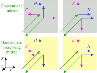
Fig. 2 compares HPM to a conventional mirror. In a conventional metallic mirror, the electric field, when reflected, reverses its phase whereas the magnetic field does not. A reverse situation is possible, in which case the mirror is called a magnetic mirror. HPM combines the electric and magnetic types of reflection Fedotov et al. (2005). Let be such an axis in the HPM plane that an electric field linearly polarized along that axis changes its phase after reflection. The orthogonal axis corresponds to magnetic reflection. It is important that the magnetic field is orthogonal to the electric one, and hence to the axis, and is directed along . In other words, the electric and magnetic field components directed along are subject to a phase jump and yield a node, i.e. zero intensity. It is only -components of the field that remain non-zero.
Maxwell equations in the basis associated with the cholesteric director
Here we limit ourselves to the case of normal light incidence. For =1, the Maxwell equation for a wave propagating along the helix axis can be written as
| (1) |
The wave is described by a vector of complex amplitudes for the electric field components in the orthogonal directions and . Projection of the dielectric permittivity tensor on the plane at the depth of cholesteric is given by
| (2) |
Here the optical axis coinciding with the cholesteric director is given by the twist angle , which is measured from the axis toward the axis; is the helix pitch. The positive pitch refers to a right-handed helix, the negative pitch refers to a left-handed one. Taking into account magnetic permittivity makes an explicit form of the magnetic strength expression more preferred and increases the field vector dimensionality from 2 to 4.
Consequently, the order of the differential equation goes down from second to first. Let us assume the principal axes of the magnetic and electric permittivity tensors to coincide. On this assumption, we can use the orthonormal basis uniformly rotating together with the cholesteric director so that the axis always goes along the director:
By the Berreman method Berreman (1972), Maxwell equations in a stationary case have the form:
| (3) |
A differential transfer matrix for rotating basis is formulated in Oldano et al. (2003); Avendaño et al. (2005) and it can be reduced as follows:
| (4) |
where is the nondimensional wavelength, is the nondimensional coordinate. There are different units for electric and magnetic strengths in the SI system, therefore they have to be normalized via the vacuum impedance .
Solution without low anisotropy approximation
Four normal waves correspond to Eq.(3). They are determined by the eigenvalues of the matrix These eigenvalues have the sense of refractive indices and the respective eigenvectors of the matrix have the sense of polarizations . Based on the -axis reversal symmetry , these four normal waves can be classified as two pairs of counter-directed waves. In each pair, the wave with a larger refractive index has a lower phase velocity. We refer to this wave as a slow wave. The other wave is called a fast wave:
| (5) |
Substituting the solution for into Eq. (3) yields:
| (6) |
where is the unit matrix, the index in has been omitted. The refractive indices are as follows
| (7) |
where is the antisymmetry coefficient of permittivities and the overbar means the arithmetic mean over ordinary and extraordinary permittivities:
| (8) |
Scale invariance of Maxwell equations (3) and normalization of material parameters (see Supplement in Avendaño et al. (2005)) reduces the structure to two crucial parameters: electric and magnetic anisotropies
| (9) |
The case of equal anisotropies,
Consider the case of equal anisotropies . The clarity and fineness of this single-parametric set of structures should compensate the difficulty of their physical realization in the optical range for the reader Gevorgyan and Rafayelyan (2013). The wavelength parameterizes the set of differential transfer matrixes (4) the way eccentricity does to a set of conical cross-sections. The dispersion equation simplifies due to the symmetry of permittivities
| (10) |
Without further prejudice to the generality, we assume the normalization , . Then . In other words, the permittivity is normalized to the geometric mean of and : , the arithmetic mean being not less than unity . The second term in the right-hand part of the dispersion equation becomes squared anisotropy . Anisotropy here acquires the meaning of the standard deviation of permittivities:
| (11) |
Unlike the parabolic approximation typical of periodic media, the dispersion curves have a hyperbola shape, except for the stop band where they have the shape of a circle. Dispersion equation (11) can be written for the refractive index as well as for the wave vector
| (12) |
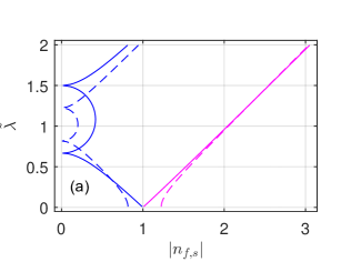
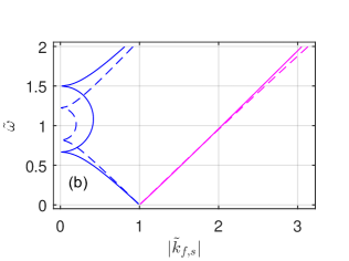
This symmetry of and dispersions indicates the symmetry of the longwave and shortwave limits. In the longwave limit, the medium is homogenized and becomes isotropic. The negative optical activity ceases as the situation comes close to the static field case. In the shortwave limit, positive optical activity is supported by the Mauguin waveguide regime (Fig. 3). This symmetry is destroyed when the anisotropies become unequal . The ordinary and extraordinary waves can then be distinguished in the high-frequency limit equivalent to helix untwisting. Next we focus on the circular Bragg diffraction, when and the refractive index for the fast wave acquires purely imaginary values. This is the case when the phase velocity becomes infinite and the group velocity – meaningless. It would be reasonable here to write down dispersion equation (11) in the form of a trigonometric identity where some angle acts instead of the wavelength, on the physical meaning of which we will dwell later.
| (13) |
This means that at wavelength
| (14) |
the refractive index of the fast wave describes full reflection in the cholesteric bulk. This wave is conventionally called a diffracting wave Belyakov (1992) and its polarization is derived from nontrivial solvability of Eq. (11). Subtracting the refractive index from transfer matrix (6) yields the following identity:
where . We deal here with a manifest symmetry with respect to exchange between electric and magnetic fields and permittivities, . The electric and magnetic permittivities being equal is equivalent to the Umov-Pointing vector going to zero the same way as for conventional standing-wave nodes and antinodes. The electric and magnetic fields are linearly polarized at the same angle to the cholesteric director. This direction coincides with the axis for . Surface conditions for an ideal HPM are exactly the same, i.e. both the electric field and the magnetic field are linearly polarized along the magnetic axis of the mirror (Fig. 2). Hence the derived expression provides an exact description of COTS for a finite anisotropy.
The case of unequal anisotropies,
In a general case, we denote directions of electric and magnetic polarizations by the angles and . Generalized nontrivial solution (12) provides eigenvectors of the transfer matrix (6) and exact solutions for the angles Becchi et al. (2004):
| (16) |
where the refractive index should be borrowed from dispersion equation (4). It is evident that the polarizations are linear for the purely imaginary refractive index whereas for the real refractive index they are almost circular in the stop band. Dispersion equation (7) can be generalized as:
| (17) |
For a cholesteric without magnetic anisotropy, , we have:
| (18) |
The eigenfrequency is:
| (19) |
This expression is more exact compared to the earlier obtained approximation (Eq.(14) in Timofeev and Vetrov (2016)) and still there remains approximation. We have to use a unified angle between the cholesteric optical axes and HPM hence the electric and magnetic polarizations are directed differently in a general case. This does not meet the condition on the HPM surface. The non-zero angle of polarization mismatch introduces a new non-local COTS component Becchi et al. (2004). This results in the state becoming a leaking mode (or resonance) and acquiring finite relaxation time .
COTS relaxation time
By definition, the time of relaxation of a vibrational state is the ratio between the stored energy, , and the lost power, , taken with a positive sign:
| (20) |
Here is the amplitude relaxation time, which is twice the energy relaxation time. Since field does not penetrate into depth of an ideal HPM, the whole stored energy is the energy of diffracting waves inside the cholesteric layer. Let us find this energy by integrating its density over space , in Gaussian units. The period-averaged densities of electric and magnetic energy components are equal because . Moreover , where is the wave amplitude. Therefore, . A standing wave in the layer is formed by two waves travelling in opposite directions. Their constructive interference is compensated by a destructive one, and their energy densities add up. In the defect layer, . Integration yelds
| (21) |
With account of Eq. (7,18) for and ,
| (22) |
Here is given by (17). The power of leakage is proportional to the flow velocity and the energy density carried away by the travelling wave. The strength is governed by the boundary conditions:
| (23) |
We finally have Becchi et al. (2004)
| (24) |
Consider a cholesteric layer of finite thickness embedded in a medium with permittivity . Instead of (23), the power of leakage at the edge of the cholesteric is given by:
| (25) |
Note that because of cholesteric boundary condition is twice higher than just exponentially decreasing by Eq. (5). Then the corresponding relaxation time is
| (26) |
which agrees with the expressions obtained in Becchi et al. (2004); Belyakov and Semenov (2011). The last formula is also directly applicable when , assuming being optical density
Temporal coupled-mode theory
By the temporal coupled-mode theory Joannopoulos et al. (2008); Manolatou et al. (1999) the resonance is described by the cyclic eigenfrequency and complex amplitude . This theory should not be confused with the spatial coupled-wave theory where the amplitudes of propagating waves are involved Kogelnik (1969); Pierce (1954). The resonance manifests itself through the amplitudes of incoming and outgoing energy fluxes:
| (27) |
Excitation via one of the ports yields the amplitude
| (28) |
Amplitudes of reflection from port into port form a scattering matrix
| (29) |
where is the Kronecker symbol. Reflections are observed as spectral peaks in the shape of Lorentz profiles with full width at half maximum <FWHM>
| (30) |
Scaling from the cyclic frequency to the frequency yields a times narrower width of the peak (30):
| (31) |
This is sufficient to allow the spectral behavior of the state to be described in terms of temporal coupled-mode theory.
In the previous section we dwelt in detail on ideal COTS with its eigenfrequency given by (17). Relaxation times (24) and (26) were used to express deviations from the ideal state associated, respectively, with the angle and the layer thickness . This appears to be sufficient to fully describe COTS in terms of TCMT. The port of coupling via angle has the cross-handed circular polarization with respect to the cholesteric twist while coupling via the cholesteric thickness has the co-handed circular polarization. Equation (29) at the resonance frequency generates the following reflection matrix:
| (32) |
where , indices and stand for the same and the opposite circular polarizations, respectively. This matrix satisfies the energy conservation law. Maximum nondiagonal reflections occur at crossover when the relaxation times become equal .
An analytical expression for the length of crossover is obtained by equalizing relaxation times (24) and (26), which yields:
| (33) |
| (34) |
This length, as is fairly noted in Kopp and Genack (2003), is difficult to measure in the twist defect of a cholesteric because of the high and the high requirements to the experiment accuracy. In the case of COTS, the magnitude appears to be substantially larger because of the HPM imperfectness and the crossover length reduces, which should simplify its experimental measuring.
TCMT applicability limits
When using TCMT to tackle the problem of coupling between a localized state and waveguides, there are certain limits imposed such as linearity, time-invariant structural parameters, energy conservation, time-reversible energy flux and weak coupling Joannopoulos et al. (2008). The model chosen a priori meets the first four requirements. The fifth one incorporates, in fact, two requirements. First, the solution derived from (27) ignores corrections with respect to a small parameter that is defined as a vibration period-to-relaxation time ratio Haus (1983). Second, the waveguide dispersion should not be large over the frequency range of the resonance Lorentz profile. For a fairly large relaxation time the Lorentz profile width tends to zero and this automatically takes care of the second requirement Joannopoulos et al. (2008). In this case, the cholesteric acts as a waveguide for waves with cross-handed circular polarization. Dispersion in the middle of the stop band is moderate. So, we believe the set of linear differential equations (27) provides an adequate description of the model when and .
Results
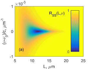
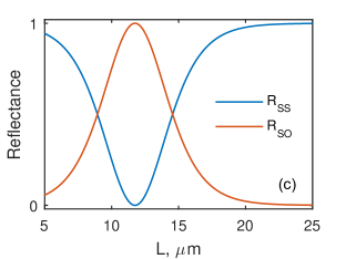
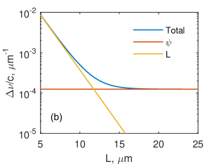
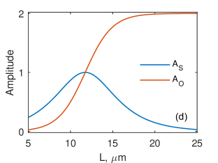
Fig. 4 shows that there is a Kopp–Genack effect observed for COTS. For definiteness, we took the helix pitch to be . For the parameters specified in the figure, the eigenfrequency is achieved at the angle , the mismatch angle being . The crossover length agrees with Eq. (34). For substantially thicker cholesteric layers, , the line width is and the quality factor saturates . Note that for crossover, , the quality is half that magnitude. Fig. 4a illustrates that for crossover , the structure reflects light as a conventional mirror, i.e. the circular polarization handedness changes for the opposite one. The growing thickness of the cholesteric layer takes its polarization properties back to the HPM properties when , i.e. the circular polarization handedness no longer changes under reflection. Fig. 4b proves that the co-handed and cross-handed (right and left) circular polarizations excite COTS equally efficiently when (crossover). Hence, the most efficient excitation occurs when both polarizations with equal amplitudes and a certain phase difference are superimposed to produce linearly polarized light. No COTS is excited by orthogonally polarized light. For thicker cholesterics, , excitation is only possible with cross-handed circularly polarized light as co-handed circularly polarized light is totally reflected from the cholesteric.
Conclusion
The chiral optical Tamm state can be considered strictly localized only provided the electric and magnetic permittivities are equal and the respective tensor axes coincide. Otherwise COTS is observed as a polarized reflection resonance with two relaxation constants determined by the permittivity difference and the cholesteric layer thickness. COTS is closely connected with the twist defect of cholesteric and renders the Kopp–Genack crossover effect. A scattering matrix, where spectral peaks are described by Lorentz profiles, has been found in terms of the temporal coupled-mode theory. It is for the first time that a formula for the cholesteric crossover thickness has been suggested, which is equally suitable for COTS and for the twist defect. The analytical result agrees with the direct numerical one.
This work was financially sponsored by the Ministry of Science and Technology (MOST), Taiwan, under grant No. <coming soon>, Russian Foundation for Basic Research, Government of Krasnoyarsk Territory, Krasnoyarsk Region Science and Technology Support Fund to the research project No. 17-42-240464, and by the Siberian Branch of the Russian Academy of Sciences under Complex Program II.2P (projects Nos. 0356-2015-0410 and 0356-2015-0411). The authors are thankful to Prof. A.F. Sadreev, Prof. E.N. Bulgakov, Dr. N.V. Rudakova, Y.-C. Hsiao and L.V. Pertseva for valuable discussions and comments.
References
- Belyakov (1992) V. A. Belyakov, Diffraction Optics of Complex-Structured Periodic Media (Springer New York, 1992) p. 352.
- Faryad and Lakhtakia (2014) M. Faryad and A. Lakhtakia, Adv. Opt. Photonics 6, 225 (2014).
- Xiang et al. (2015) J. Xiang, Y. Li, Q. Li, D. A. Paterson, J. M. D. Storey, C. T. Imrie, and O. D. Lavrentovich, Adv. Mater. 27, 3014 (2015).
- Avendaño et al. (2005) C. G. Avendaño, S. Ponti, J. A. Reyes, and C. Oldano, J. Phys. A: Math. Gen. 38, 8821 (2005).
- Haus and Shank (1976) H. Haus and C. Shank, IEEE J. Quantum Electron. 12, 532 (1976).
- Lakhtakia and McCall (1999) A. Lakhtakia and M. McCall, Opt. Commun. 168, 457 (1999).
- Yang et al. (1999) Y.-C. Yang, C.-S. Kee, J.-E. Kim, H. Y. Park, J.-C. Lee, and Y.-J. Jeon, Phys. Rev. E 60, 6852 (1999).
- Shabanov et al. (2004) A. V. Shabanov, S. Y. Vetrov, and A. Y. Karneev, J. Exp. Theor. Phys. Lett. 80, 181 (2004).
- Gevorgyan (2006) A. H. Gevorgyan, Tech. Phys. Lett. 32, 698 (2006).
- Belyakov and Semenov (2011) V. A. Belyakov and S. V. Semenov, J. Exp. Theor. Phys. 112, 694 (2011).
- Kiselev and Chigrinov (2014) A. D. Kiselev and V. G. Chigrinov, Phys. Rev. E 90, 042504 (2014), arXiv:1407.3534 .
- Hsiao et al. (2014) Y.-C. Hsiao, H.-T. H.-T. Wang, and W. Lee, Opt. Express 22, 3593 (2014).
- Rodarte et al. (2015) A. Rodarte, F. Cisneros, J. Hein, S. Ghosh, and L. Hirst, Photonics 2, 855 (2015).
- Lin et al. (2015) J.-D. Lin, C.-L. Chu, H.-Y. Lin, B. You, C.-T. Horng, S.-Y. Huang, T.-S. Mo, C.-Y. Huang, and C.-R. Lee, Opt. Mater. Express 5, 1419 (2015).
- Kesaev et al. (2016) V. V. Kesaev, E. P. Pozhidaev, and A. D. Kiselev, (2016), arXiv:1610.08240 .
- Hodgkinson et al. (2000) I. J. Hodgkinson, Q. H. Wu, K. E. Thorn, A. Lakhtakia, and M. W. McCall, Opt. Commun. 184, 57 (2000).
- Kopp and Genack (2002) V. I. Kopp and A. Z. Genack, Phys. Rev. Lett. 89, 033901 (2002).
- Oldano et al. (2003) C. Oldano, J. A. Reyes, and S. Ponti, Phys. Rev. E 67, 056624 (2003).
- Becchi et al. (2004) M. Becchi, S. Ponti, J. Reyes, and C. Oldano, Phys. Rev. B 70, 033103 (2004).
- Schmidtke and Stille (2003) J. Schmidtke and W. Stille, Eur. Phys. J. E - Soft Matter 12, 553 (2003).
- Schmidtke et al. (2003) J. Schmidtke, W. Stille, and H. Finkelmann, Phys. Rev. Lett. 90, 083902 (2003).
- Ozaki et al. (2003) M. Ozaki, R. Ozaki, T. Matsui, and K. Yoshino, Jpn. J. Appl. Phys. 42, L472 (2003).
- Shibaev et al. (2002) P. V. Shibaev, K. Tang, A. Z. Genack, V. Kopp, and M. M. Green, Macromolecules 35, 3022 (2002).
- Oldano (2003) C. Oldano, Phys. Rev. Lett. 91, 259401 (2003).
- Kopp and Genack (2003) V. Kopp and A. Genack, Phys. Rev. Lett. 91, 259402 (2003).
- Gevorgyan and Rafayelyan (2013) A. H. Gevorgyan and M. S. Rafayelyan, J. Opt. (United Kingdom) 15, 125103 (2013).
- McCall et al. (2015) M. W. McCall, I. J. Hodgkinson, and Q. Wu, Birefringent Thin Films and Polarizing Elements: 2nd Edition, 2nd ed. (Imperial College Press, 2015).
- Belyakov and Shilina (1992) V. A. Belyakov and G. I. Shilina, Mol. Cryst. Liq. Cryst. 223, 55 (1992).
- Kavokin et al. (2005) A. Kavokin, I. Shelykh, and G. Malpuech, Appl. Phys. Lett. 87, 261105 (2005).
- Vinogradov et al. (2010) A. P. Vinogradov, A. V. Dorofeenko, A. M. Merzlikin, and A. A. Lisyansky, Uspekhi Fiz. Nauk 53, 243 (2010).
- Iorsh et al. (2012) I. V. Iorsh, P. A. Belov, A. A. Zharov, I. V. Shadrivov, and Y. S. Kivshar, Phys. Rev. A 86, 023819 (2012).
- Afinogenov et al. (2013) B. I. Afinogenov, V. O. Bessonov, A. A. Nikulin, and A. A. Fedyanin, Appl. Phys. Lett. 103, 061112 (2013).
- Auguié et al. (2015) B. Auguié, A. Bruchhausen, and A. Fainstein, J. Opt. (United Kingdom) 17, 035003 (2015), arXiv:1411.0608 .
- Chang et al. (2015) C. Y. Chang, Y. H. Chen, Y. L. Tsai, H. C. Kuo, and K. P. Chen, IEEE J. Sel. Top. Quantum Electron. 21 (2015), 10.1109/JSTQE.2014.2375151.
- Yang et al. (2016) Z.-Y. Yang, S. Ishii, T. Yokoyama, T. D. Dao, M.-g. Sun, T. Nagao, and K. P. Chen, Opt. Lett. 41, 4453 (2016).
- Kaliteevski et al. (2007) M. Kaliteevski, I. Iorsh, S. Brand, R. A. Abram, J. M. Chamberlain, A. V. Kavokin, and I. A. Shelykh, Phys. Rev. B 76, 165415 (2007).
- Abdulhalim (2006) I. Abdulhalim, Opt. Lett. 31, 3019 (2006).
- Timofeev et al. (2013) I. V. Timofeev, V. G. Arkhipkin, S. Y. Vetrov, V. Y. Zyryanov, and W. Lee, Opt. Mater. Express 3, 496 (2013).
- Vetrov et al. (2014) S. Y. Vetrov, M. V. Pyatnov, and I. V. Timofeev, Opt. Lett. 39, 2743 (2014).
- Vetrov et al. (2016) S. Y. Vetrov, M. V. Pyatnov, and I. V. Timofeev, J. Opt. (United Kingdom) 18, 015103 (2016), arXiv:1506.04590 .
- Pyatnov et al. (2016) M. V. Pyatnov, S. Y. Vetrov, and I. V. Timofeev, Liq. Cryst. (2016), 10.1080/02678292.2016.1229055.
- Zhuang and Patel (1999) Z. Zhuang and J. S. Patel, Opt. Lett. 24, 1759 (1999).
- Isaacs et al. (2014) S. Isaacs, F. Placido, and I. Abdulhalim, Appl. Opt. 53, H91 (2014).
- Hsiao et al. (2011) Y.-C. Hsiao, C.-T. C.-T. Hou, V. Y. Zyryanov, and W. Lee, Opt. Express 19, 23952 (2011).
- Timofeev et al. (2012) I. V. Timofeev, Y.-T. Lin, V. A. Gunyakov, S. A. Myslivets, V. G. Arkhipkin, S. Y. Vetrov, W. Lee, and V. Y. Zyryanov, Phys. Rev. E 85 (2012), 10.1103/PhysRevE.85.011705.
- Timofeev and Vetrov (2016) I. V. Timofeev and S. Y. Vetrov, JETP Lett. 104, 380 (2016), arXiv:1608.01876 .
- Gunyakov et al. (2016) V. A. Gunyakov, M. Krakhalev, V. Zyryanov, V. Shabanov, and V. Loiko, J. Quant. Spectrosc. Radiat. Transf. 178, 152 (2016).
- Huang et al. (2016) K.-C. Huang, Y.-C. Hsiao, I. V. Timofeev, V. Y. Zyryanov, and W. Lee, Opt. Express 24, 25019 (2016).
- Plum and Zheludev (2015) E. Plum and N. I. Zheludev, Appl. Phys. Lett. 106, 221901 (2015).
- Fedotov et al. (2005) V. Fedotov, A. Rogacheva, A. Schwanecke, R. Mladyonov, S. Prosvirnin, Y. Cheni, and N. Zheludev, in 2005 IEEE LEOS Annu. Meet. Conf. Proc., Vol. 2005 (IEEE, 2005) pp. 539–540.
- Rudakova et al. (2017) N. V. Rudakova, I. V. Timofeev, P. S. Pankin, and S. Y. Vetrov, Bull. Russ. Acad. Sci. Phys. 81, 10 (2017).
- Ding et al. (2015) F. Ding, Z. Wang, S. He, V. M. Shalaev, and A. V. Kildishev, ACS Nano 9, 4111 (2015).
- Berreman (1972) D. W. Berreman, J. Opt. Soc. Am. 62, 502 (1972).
- Palto (2001) S. P. Palto, J. Exp. Theor. Phys. 92, 552 (2001).
- Oseen (1933) C. Oseen, Trans. Faraday Soc. 29, 883 (1933).
- de Vries (1951) H. de Vries, Acta Crystallogr. 4, 219 (1951).
- Kats (1971) E. Kats, J. Exp. Theor. Phys. 32, 1004 (1971).
- Nityananda (1973) R. Nityananda, Mol. Cryst. Liq. Cryst. 21, 315 (1973).
- Haus (1983) H. A. Haus, Waves and fields in optoelectronics, Prentice-Hall Series in Solid State Physical Electronics (Prentice Hall, Incorporated, 1983) p. 402.
- Manolatou and Haus (2002) C. Manolatou and H. A. Haus, Passive Components for Dense Optical Integration (2002) p. 173.
- Joannopoulos et al. (2008) J. D. Joannopoulos, S. G. Johnson, J. N. Winn, and R. D. Meade, Photonic Crystals: Molding the Flow of Light (Second Edition) (Princeton University Press, 2008) p. 304.
- Fan et al. (2003) S. Fan, W. Suh, and J. D. Joannopoulos, J. Opt. Soc. Am. A 20, 569 (2003).
- Xu et al. (2000) Y. Xu, Y. Li, R. K. Lee, and A. Yariv, Phys. Rev. E 62, 7389 (2000).
- Bliokh et al. (2008) K. Y. Bliokh, Y. P. Bliokh, V. Freilikher, S. Savel’ev, and F. Nori, Rev. Mod. Phys. 80, 1201 (2008), arXiv:0708.2653 .
- Lippmann and Schwinger (1950) B. A. Lippmann and J. Schwinger, Phys. Rev. 79, 469 (1950).
- Kogelnik (1969) H. Kogelnik, Bell Syst. Tech. J. 48, 2909 (1969).
- Yariv (1973) A. Yariv, IEEE J. Quantum Electron. 9, 919 (1973).
- Belyakov and Dmitrienko (1974) V. A. Belyakov and V. E. Dmitrienko, Sov. Phys. Solid State 15, 1811 (1974).
- Belyakov et al. (1979) V. A. Belyakov, V. E. Dmitrienko, and V. P. Orlov, Sov. Phys. Uspekhi 22, 64 (1979).
- Belyakov et al. (1992) V. A. Belyakov, V. P. Orlov, and G. I. Shilina, J. Exp. Theor. Phys. 75, 189 (1992).
- McCall and Lakhtakia (2000) M. W. McCall and A. Lakhtakia, J. Mod. Opt. 47, 973 (2000).
- Wang and Lakhtakia (2005) F. Wang and A. Lakhtakia, Proc. R. Soc. A Math. Phys. Eng. Sci. 461, 2985 (2005).
- Pierce (1954) J. R. Pierce, J. Appl. Phys. 25, 179 (1954).
- Manolatou et al. (1999) C. Manolatou, M. Khan, S. Fan, P. Villeneuve, H. Haus, and J. D. Joannopoulos, IEEE J. Quantum Electron. 35, 1322 (1999).