Development of optical resonant cavities for laser-Compton scattering
Abstract
We have been developing optical resonant cavities for laser-Compton scattering experiment at the Accelerator Test Facility in KEK. The main subject of the R&D is to increase laser pulse energy by coherently accumulating the pulses in an optical resonant cavity. We report previous results, current status and future prospects, including a new idea of an optical resonant cavity.
keywords:
laser-Compton scattering, optical resonant cavity, self-resonating cavity1 Introduction
Laser-Compton scattering is an attractive method to generate photons in an energy range from x to rays. The advantages of of this scheme are; the required electron energy is lower than those of synchrotron radiation, polarized photons can be produced and easily controlled by the incident laser beam polarization. Thanks to these advantages, this scheme can be applied to a wide area of scientific and industrial fields such as material science, medical science, particle-nuclear physics, and therefore, its characteristics and possible applications have been discussed by many authors [1, 2, 3, 4, 5, 6, 7, 8, 9, 10, 11, 12].
One of the issues of the laser-Compton scheme is to obtain sufficient photon intensity for various applications. An optical resonant cavity is an idea to provide high power and high repetition laser pulses by coherently accumulating them in the cavity, which allows us to construct a laser-Compton facility without a large scale laser system. For the coherent superposition of laser pulses, however, the length of the optical path in the cavity should be multiples of the wavelength with high precision, that reaches O (10) pm for the finesse of . Therefore, controlling the optical path length is a key issue to realize the laser system with the high finesse optical cavity.
We have developed optical cavities and performed a series of experiment to generate photon beams by laser-Compton scattering at the Accelerator Test Facility (ATF) in KEK, Japan, by the collaboration of KEK, Waseda University and Hiroshima University with a close information exchange with a group of LAL Orsay, France. The initial results were published in [13, 14]. At the latest experiment, we successfully kept the optical path length of the cavity with the order of 10 pm and enhanced the laser pulse intensity to 1230 times in the cavity [15].
For more power enhancement in the cavity, one order higher for example, the required precision will reach O(1) pm. It could be achieved with a sophisticated optical and feedback system, however, is technically challenging to develop such system. As an alternative of precise control of the optical path length by active feedback system, we proposed an idea of self-resonating cavity, in which the optical system composed of a laser amplifier and an optical cavity keeps resonance condition by itself [22].
In this article, we report a status and prospect of our effort to develop optical cavities for laser-Compton scattering, including a self-resonating cavity.
2 4 Mirror Optical Cavity in the KEK ATF
A schematic of an optical cavity installed in the ATF is shown in figure 1. The cavity is a 4 mirror ring cavity with the optical path length of about 1.68 m. A discussion about various configurations of the 4 mirrors cavities is find in [16]. Comparing with a simple two mirror cavity, the 4 mirror cavity has advantages of stability against miss-alignment of the mirrors. particularly for an operation with a tight laser beam focusing [15]. The main parameters of the ATF and laser pulses used in the experiments are summarized in table 1.
| Electron | |
| Energy | 1.28 GeV |
| Energy Spread | |
| Beam Intensity | /bunch |
| Bunch Spacing | 5.6 ns |
| Circumference | 138.6 m |
| Emittance () | |
| Revolution | 2.16 MHz |
| Laser | |
| Wavelength | 1064 nm |
| Repetition frequency | 357 MHz |
| Pulse width | 11 ps (FWHM) |
| Power | 10 W (28nJ/pulse) |
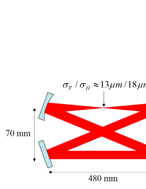
A unique feature of the cavity is that the 4 mirrors of the cavity are arranged in a way to make a twisted optical path for the circulating laser pulses. It causes a geometric phase for a laser wave state in the cavity, and as a result, the cavity only resonates with left- or right- circularly polarized state separately at different optical path length. This feature is useful for generating circularly polarized photon via laser-Compton scattering and also applicable to a feedback control scheme with a simple setup [17].
We conducted the laser-Compton experiments at the KEK ATF, an electron storage ring which was constructed to develop technique for an ultra-low emittance electron beam required for future linear colliders [18].
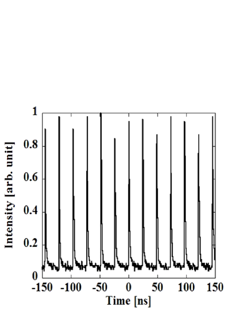
Figure 2 shows the stored power in the cavity during the operation in the ATF ring.
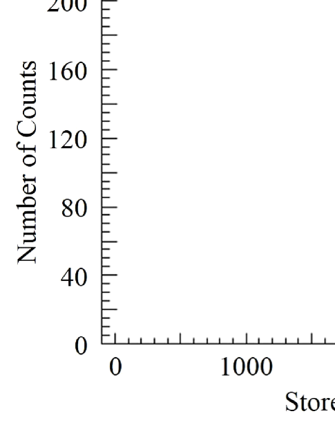
The average power was observed to be 2.6 kW. Since the input power to the cavity was 2.1 W, the stored power was enhanced by a factor of 1230. From the fluctuation of the stored power, 38 W, the precision of the optical path control was calculated to be pm. We also succeeded to generate rays at the rate of with their average energy of 24 MeV
It must be mentioned, while not discussed in this article, another 4 mirror optical cavity was installed by the French group in the ATF and successfully demonstrated photon generation of photons per second with an average power in the cavity of 35 kW [20, 21]. The cavity equipped an automated mirror alignment system with Pound-Drever-Hall stabilizing technique, while the cavity described in this article adopted relatively simple mechanical configuration and the polarization based feedback system. The average photon yield depended on the electron beam conditions during the experiments, which eventually gave us a similar number of photons per second. The photon yields normalized by the electron intensity for both experiments were consistent with the laser power and the French cavity showed approximately 400 photons per laser-election pulse interaction, which is the world record at the time of the publication [20].
3 Self-resonating Optical cavity
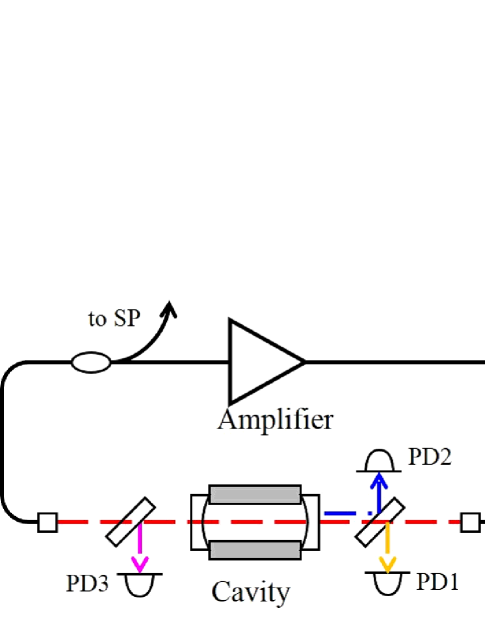
The obtained photon yields of , described in the previous section, are still not sufficient for realistic applications, thus we need to increase intensity of both electron and laser beams. In terms of the laser power in the optical cavities, the required precision of the optical path control will reach order of picometers or less. To avoid the technical difficulty, an idea of the self-resonating cavity was proposed [22]. A configuration of the self-resonating cavity is illustrated in figure 3, which forms an optical loop with a laser amplifier and an optical cavity. At the beginning, a laser wave which satisfies the resonance condition, , circulates in the optical loop and acts as a seed of the laser oscillation. When the gain of the amplifier becomes sufficient to compensate over all power loss in the loop, the laser oscillation starts spontaneously with a wavelength which satisfies the resonance condition. The length of the cavity, , and therefore the resonance wavelength, fluctuates due to environmental disturbances, however, the system, in principle, keeps the laser oscillation with a new wavelength chosen by the cavity. We demonstrated the idea with a two mirror Fabry Perrot cavity[23]. The reflectivity of the mirrors are 99.999% and the intrinsic finesse of the cavity was independently measured to be .
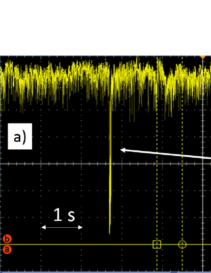
As the first trial, we operated the system with continuous wave laser with the wavelength around 1047 nm. We observed a highly stable operation with the power fluctuation of % for more than two hours. Figure 4 shows a demonstration of the stability of the self-resonating cavity. During a stable operation of the cavity, we hit the body of the cavity with a hammer. A sharp drop of the stored power was observed, but was automatically restored in about 40 ms, which was consistent with a damping time of the mechanical vibration of the body of the cavity.
The effective finesse, which is a measure of the performance of the cavity including the stability of self-resonating mechanism, was measured to be . The stored power in the cavity, which was calculated from the transmitted power with the transmittance of the mirror, was kW, showing a power enhancement factor of approximately 187,000.
Toward application of this idea to the laser-Compton scattering, the mode locked pulsed oscillation is necessary. It requires a mechanism to make pulses in the system such as a nonlinear polarization rotation optics. In addition, mode locked oscillation requires a relation between the entire optical path and the cavity length as , where and are the optical path length of the entire loop and the length of the cavity embedded in the optical loop. We succeeded a proof of the principle experiment of a mode locked oscillation with low finesse (about 220) cavity as shown in figure 5. The details of the mode locked operation can be found in [24] and the R&D toward a stable and high power storage is now in progress.
4 Conclusion
A series of experiments has been performed at the ATF electron ring in KEK and demonstrated photon generation by laser-Compton scattering.
A new cavity based on the self-resonating mechanism has been developed and we successfully demonstrated a stable operation with continuous wave. An effort is in progress toward realization of stable mode lock operation for the laser-Compton experiment.
Acknowledgment
The authors would like to thank the members of the ATF group and collaborators of LAL Orsay, France. This research has been supported by Quantum Beam Technology Program of Japanese Mext and also supported by JSPS KAKENHI Grant numbers 23226020, 24654076 and 25246039
References
- [1] G. A. Krafft and G. Priebe, Rev. Accel. Sci. Technol. Vol. 3 (2010) 147-163
- [2] C. Sun and Y. K. Wu, Phys. Rev. ST Accel. Beams 14, 044701 (2011)
- [3] W. J. Brown and F. V. Hartemann, Phys. Rev. ST Accel. Beams 7, 060703 (2004)
- [4] V. Petrillo et al., Nucl. Instr. Meth. Phys. Res. A 693 (2012) 109
- [5] V. Petrillo et al., Phys. Rev. ST Accel. Beams 18 (2015)
- [6] L. Serafini et al, EPJ Web of Conferences 117 (2016) 05002
- [7] P. Chen, et.al, Nulc. Instr. and Meth. A397 458-464 (1997), https://ilc.kek.jp/ yokoya/CAIN/cain235/
- [8] B. Badelek, et.al, Int. J. of Mod. Phys. A19 5097 (2004)
- [9] T. Omori, et. al, Phys. Rev. Lett. 96, 114801 (2006)
- [10] R. Chiche, et. al, Appl. Opt 52 8377 (2013)
- [11] M. Bech, et. al, J. Synchrotron Rad. 16, 43 (2009).
- [12] K. Sakaue, et. al, Rev. Sci. Intr. Vol. 80. No. 12, 123304 (2009).
- [13] H. Simizu et. al, J. of Phys. Sco. of Japan. 78-7, 074501 (2009).
- [14] S. Miyoshi et. al, Nucl. Instr. and Meth. A 623, 576 (2010).
- [15] T. Akagi et. al, Nucl. Instr. and Meth. A 724, 63 (2013).
- [16] F. Zomer, et. al, Appl. Opt. Vol. 48, No. 35, 6651 (2009).
- [17] Y. Honda, et.al, Opt. Comm. Vol. 282. No. 15, 3108 (2009) T. Akagi, et. al, Rev. Sci. Instrum. 86, 043303 (2015).
- [18] J. Urakawa et al. (ATF Collaboration), http://atf.kek.jp/ collab/ap/.
- [19] A. Borzsonyi, et.al, Appl. Opt. 52, 8377 (2013).
- [20] I. Chaikovska et al, Scientific Reports 6 (2016)
- [21] J. Bonis et al, J. of Inst 7 (2012) P01017
- [22] Y. Honda, et. al. Proc. 7th Annual Meeting of PASJ, 1102 (2010), In Japanese.
- [23] Y. Uesugi, et. al, APL Photonics 1, 026103 (2016).
- [24] Y. Hosaka, et. al, arXiv:1610.03141