Mirror Position Determination
for the Alignment of Cherenkov Telescopes
Abstract
Imaging Atmospheric Cherenkov Telescopes (IACTs) need imaging optics with large apertures to map the faint Cherenkov light emitted in extensive air showers onto their image sensors. Segmented reflectors fulfill these needs using mass produced and light weight mirror facets. However, as the overall image is the sum of the individual mirror facet images, alignment is important. Here we present a method to determine the mirror facet positions on a segmented reflector in a very direct way. Our method reconstructs the mirror facet positions from photographs and a laser distance meter measurement which goes from the center of the image sensor plane to the center of each mirror facet. We use our method to both align the mirror facet positions and to feed the measured positions into our Imaging Atmospheric Cherenkov Telescope (IACT) simulation. We demonstrate our implementation on the m First Geiger-mode Avalanche Cherenkov Telescope (FACT).
keywords:
Mirror alignment, segmented reflector, point spread function1 Introduction
Imaging Atmospheric Cherenkov Telescopes (IACTs) have large effective areas to observe cosmic ray and gamma ray air showers and so have opened the very high energy gamma ray sky in the 1 tera electron Volt regime to astronomy. Almost [1] all former [2, 3], current [4, 5, 6, 7, 8], and future IACTs [9, 10] make use of segmented imaging reflectors with apertures from about m2 up to several m2. Segmented imaging reflectors with identical facets can be mass produced cost efficiently with an acceptable imaging quality which makes them a great choice for IACTs. In IACT observations, characteristic spatial and temporal features, found in the recorded image sequences, separate the few gamma ray induced events from the much more numerous set of hadronic events. However, manipulating the mirror facet orientations and positions to improve the image quality is a challenge. Such alignment manipulations are not only important during the installation but also in case of repair and replacement of facets. Here we present a method to measure and align the mirror facet positions with respect to the image sensor plane of the FACT IACT very directly and with only minimal modifications to the telescope. Our mirror position determination tool can be an addition to an already existing mirror facet orientation alignment tool, to further reduce the Point Spread Function (PSF) area in the regime. Beside its performance, our tool provides a well defined and simple procedure to maintain, refurbish, or characterize segmented imaging reflectors over their long life times.
2 Motivation
The first motivation is performance. If one already has a mirror facet orientation alignment tool [3, 11], [12, 13, 14], [15, 6], and one wants to max out the performance of one’s segmented imaging reflector, one might profit from a mirror facet position alignment system to gain in spatial and temporal resolution. To quantify the performance impact, we simulate the PSF of FACT for first, a global offset of all mirror facets, and second a normally distributed spread of the individual mirror facet positions around their target positions.
The Figures 1, 2 and 3 show the mean and the uncertainty of this mean for the two performance indicators PSF area and arrival time spread based on simulated distributions of 120 trails. Here, only the mirror facet center positions along the optical axis are varied and the mirror facet orientations are always chosen accordingly to have the minimal PSF area which corresponds to an optimal orientation alignment. The presented PSF area is not for on axis light, but for the more representative off axis region ( of FACT’s field of view radius of ). We choose the range for the offset and the spread to be up to mm ( of FACT’s focal length).
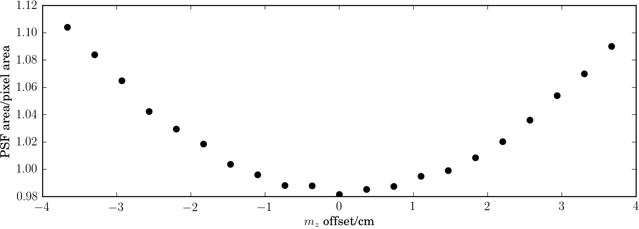
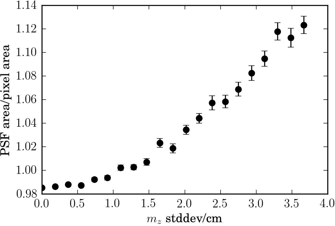
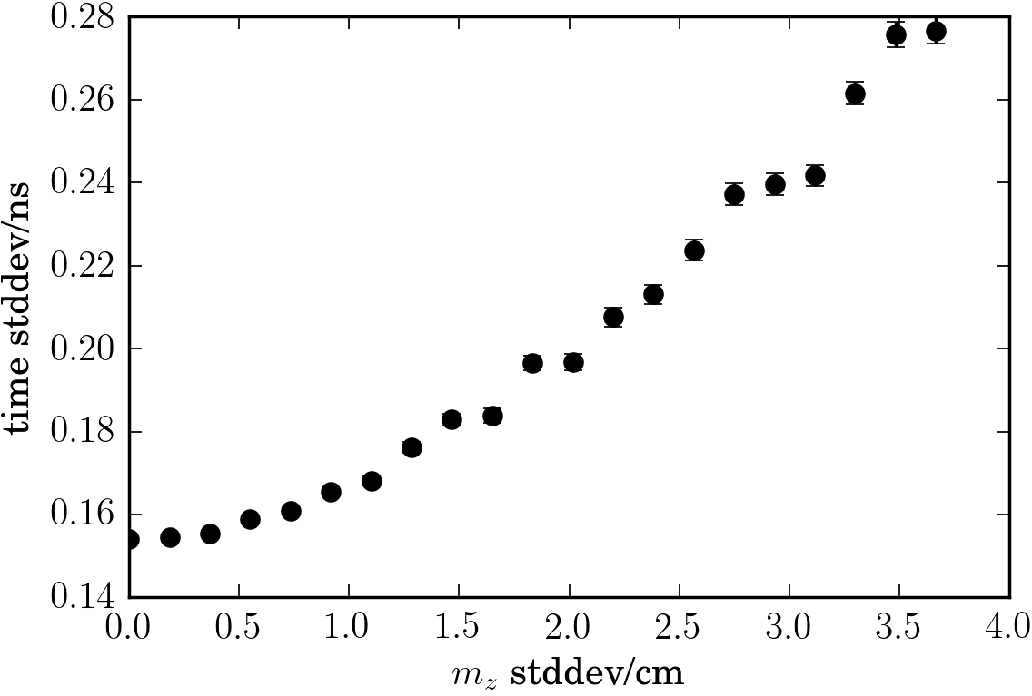
For FACT, we estimate from the simulations to have reduced the PSF area and the reflector time spread by due to our mirror facet fine positioning system.
The second motivation is to provide an easy and safe maintenance procedure.
For FACT, we want to make the most out of the vintage, but powerful components we inherited from the HEGRA [16] IACT array and so we designed the Mirror Position Determination (MIPOD) tool to fine align and measure the mirror facet positions in a reliable way while avoiding climbing on the reflector.
The task of mirror facet position alignment is usually neglected, because the optical support structure produces the mirror facet target positions well in the first place.
However, repair and upgrades will cause the mirror facet positions to deviate from their target positions over the life time of an IACT.
For example in the case of FACT, we modified the geometry of the segmented reflector in May 2014 from a pure Davies Cotton design [17] towards a hybrid of Davies Cotton and parabola design to max out the timing resolution of FACT’s modern camera [18].
In this process, all the mirror facet positions along the optical axis need adjustments, which vary from mm for some of the innermost mirror facets to mm for some of the outermost facets.
Our MIPOD tool helped us to apply these unforeseen hardware changes to FACT’s refurbished HEGRA mount.
A third motivation for a mirror facet position determination is to measure the current state of a segmented reflector without modifying it to keep the IACT simulations up to date, and to investigate gravitational slump.
3 Method and Implementation
In our MIPOD implementation, we describe the positions of the mirror facets with respect to the telescope’s principal aperture plane. First, we measure the mirror facet positions and perpendicular to the optical axis of the telescope using photographs of the segmented reflector’s aperture. Second, we calculate the mirror facet positions parallel to the optical axis by measuring the distances from the center of each mirror facet to the center of the image sensor plane with a remotely actuated Laser Distance Meter (LDM).
3.1 Mirror facet positions perpendicular to the optical axis, and
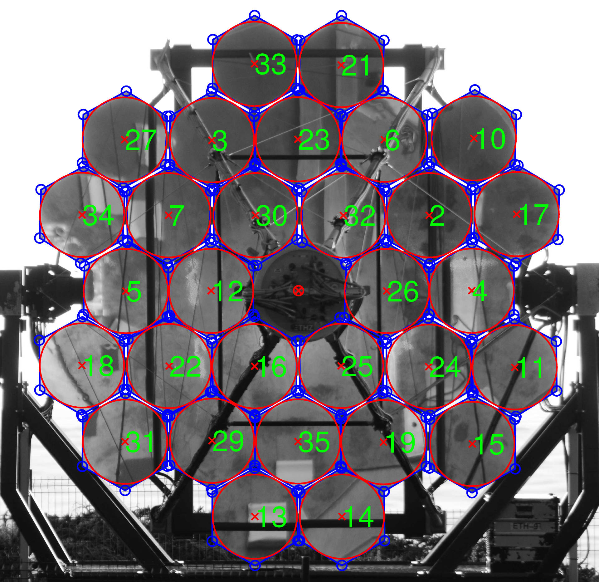
We reconstruct and of a mirror facet in three steps using a photo camera to take pictures of the aperture of the telescope while the telescope and the photo camera are facing each other, see Figure 4. First, we determine the scaling factor between distances in the picture with respect to distances on the segmented reflector by observing features in the picture which have well defined sizes, e.g. the mirror facet dimensions. Second, we find the mirror facet positions in the picture by e.g. calculating the average of the mirror facet hexagonal corner positions. Third, we calculate the mirror facet positions and from the positions in the picture and the scaling factor.
The uncertainties and are estimated to be mm (0.03% of the aperture diameter) using the spread across all the mirror facet edge lengths determined in the picture.
3.2 Mirror facet positions parallel to the optical axis,
We calculate the -th mirror facet position parallel to the optical axis by measuring the distance from the center of the -th mirror facet to the center of the image sensor plane
| (1) |
Here, is the distance of the image sensor plane to the principal aperture plane, resulting from the reflector’s focal length and the desired object distance to focus on.
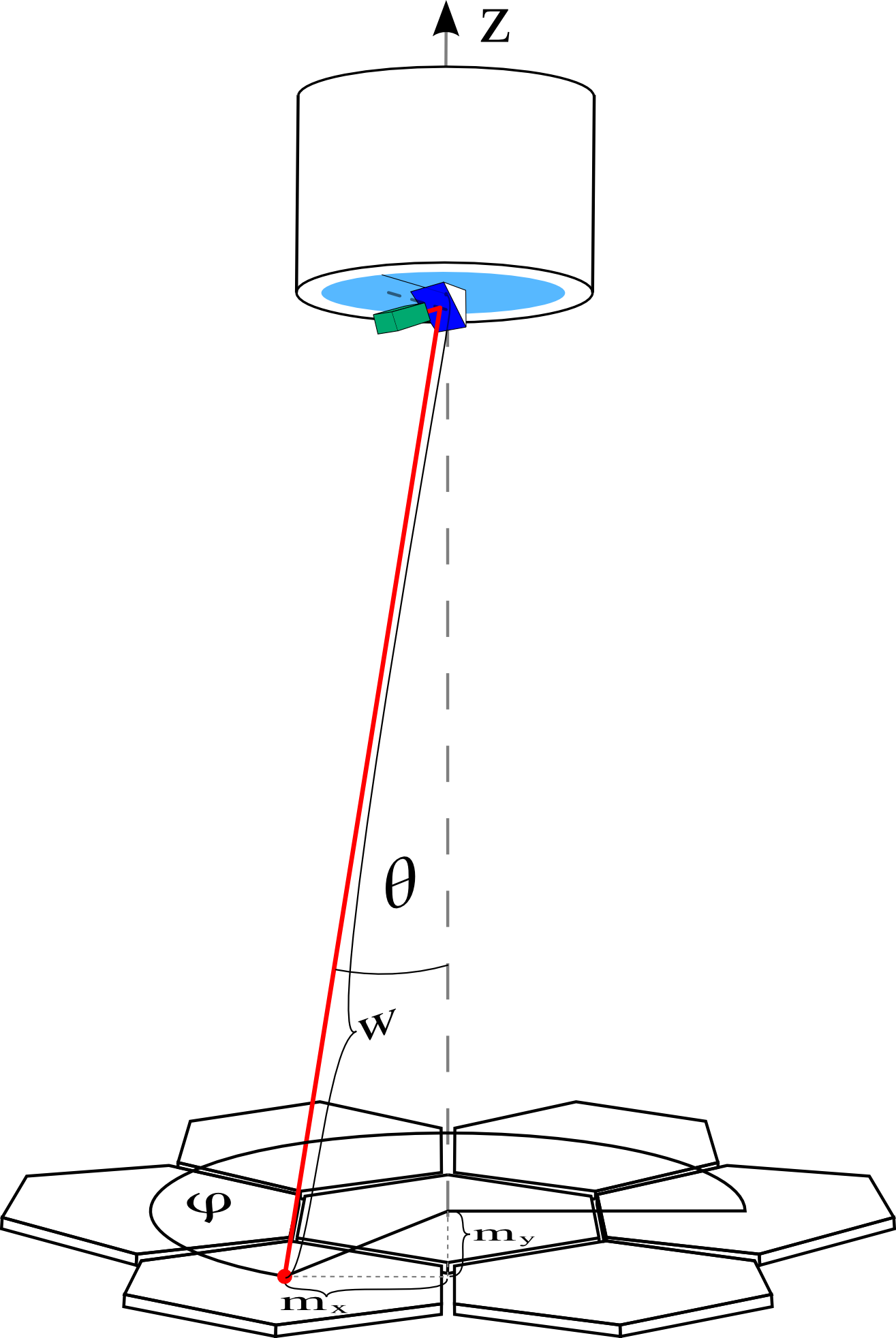
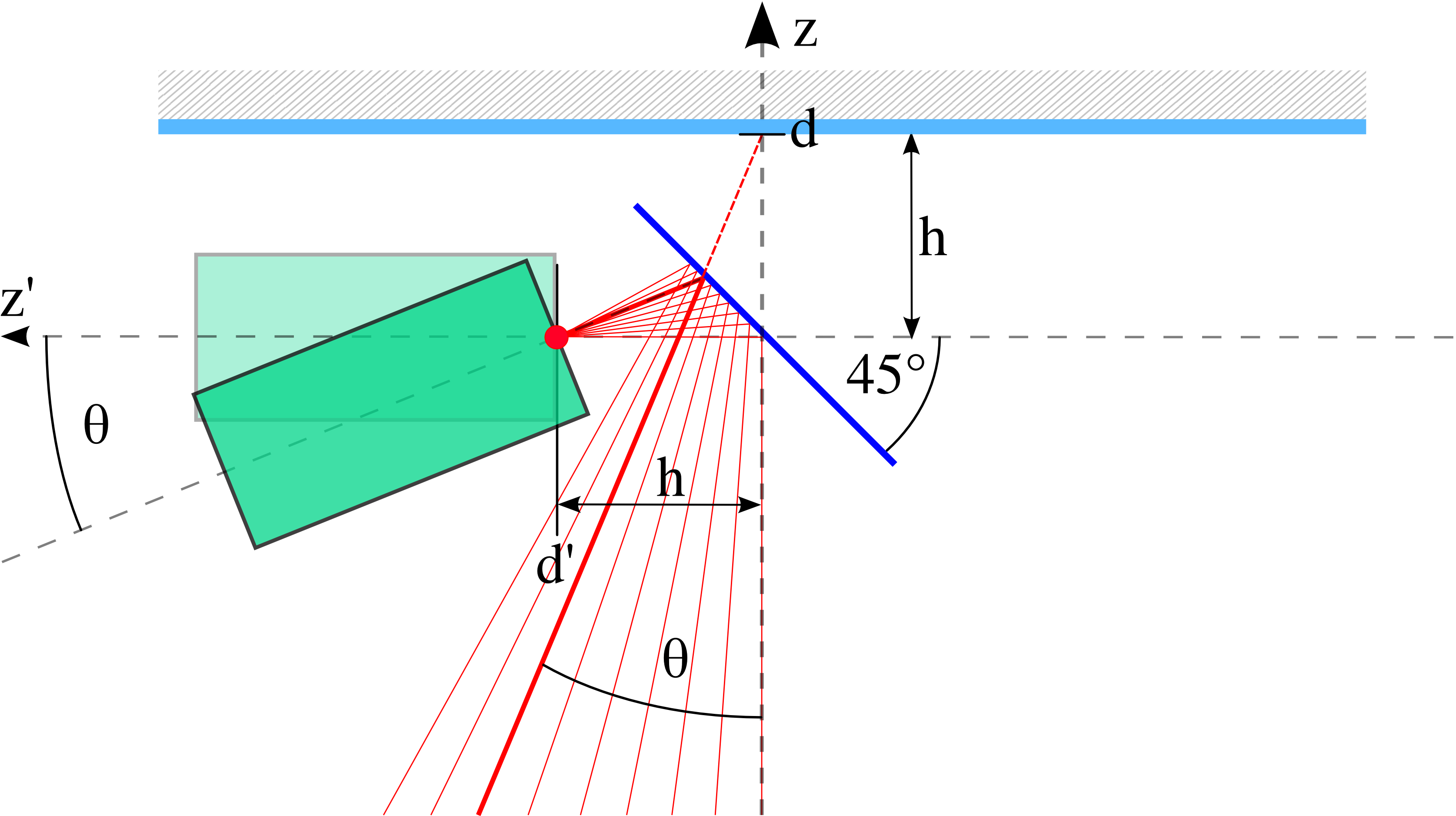
A Laser Distance Meter (LDM) measures the distances while being remotely guided from one mirror facet to the next one, see Figure 5. To not touch the image sensor plane but to still measure as directly as possible, we were inspired by [13] and place the LDM on the virtual optical axis provided by a -mirror on top of the image sensor plane of the telescope, see Figure 6. We say our MIPOD measures the mirror facet positions rather directly because its mechanic defines the center of the image sensor plane as the main reference point. This way, the number of measurements to determine a mirror facet position relative to the image sensor plane is lower than for methods which use arbitrary external reference points and therefore need to measure the position of the image sensor plane center additionally. The direct measurement of further allows our MIPOD to be practically used without a single line of software to interpret the intermediate measurements.
To point the laser beam of the LDM to all the mirror facets, we implemented two consecutive actuated joints to rotate the LDM in and . The rotation axes of the joints are chosen such that the virtual emission point of the LDM is always in the center of the image sensor plane of the telescope, see Figure 6. The first actuated joint rotates the -mirror together with the second actuator and the LDM in around the optical axis of the telescope. The second actuator tilts the LDM in around the virtual image sensor center on . The two axis joint can reliably move the beam of the LDM on spots only in diameter (mm respectively when mounted on FACT). Based on cross check measurements in the lab, we estimate the uncertainty of the LDM together with the actuated joints to be mm for typical distances on FACT (m).
3.3 Slim optical table with and -joint
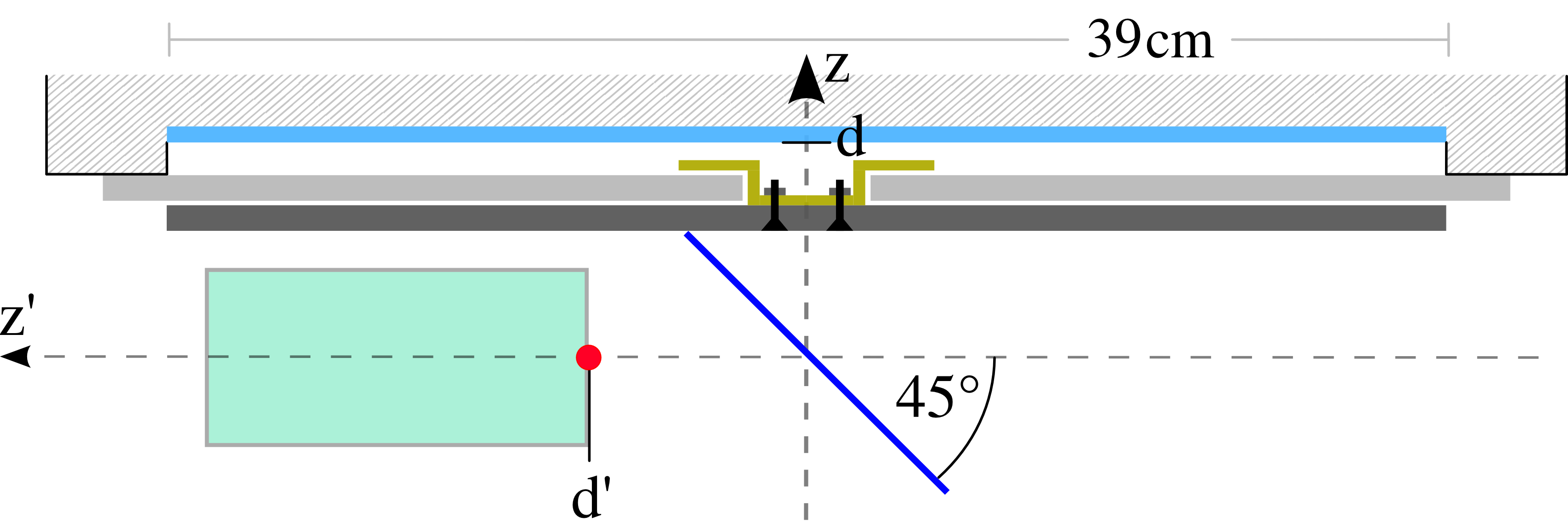
For a compact and lightweight mounting of the LDM, and therefore a reliable measurement of , the distance from the image sensor plane to the virtual optical axis should be small, see Figure 6. If is too large, the LDM mounting position might be too distant from the optical axis , and might conflict with other components of the camera in order for the LDM to freely rotate in and . In our implementation we approach this goal with two design features of the optical table which connects the remotely actuated LDM to the telescope. First, our optical table has the -joint built right into it. Second, we use permanent magnets to mount components on the optical table instead of clamping plates with shape connectors, which reduces the thickness of the optical table down to only mm. Figure 7 shows the optical table used in our MIPOD implementation and Figure 8 shows a section view of it when mounted on a telescope.
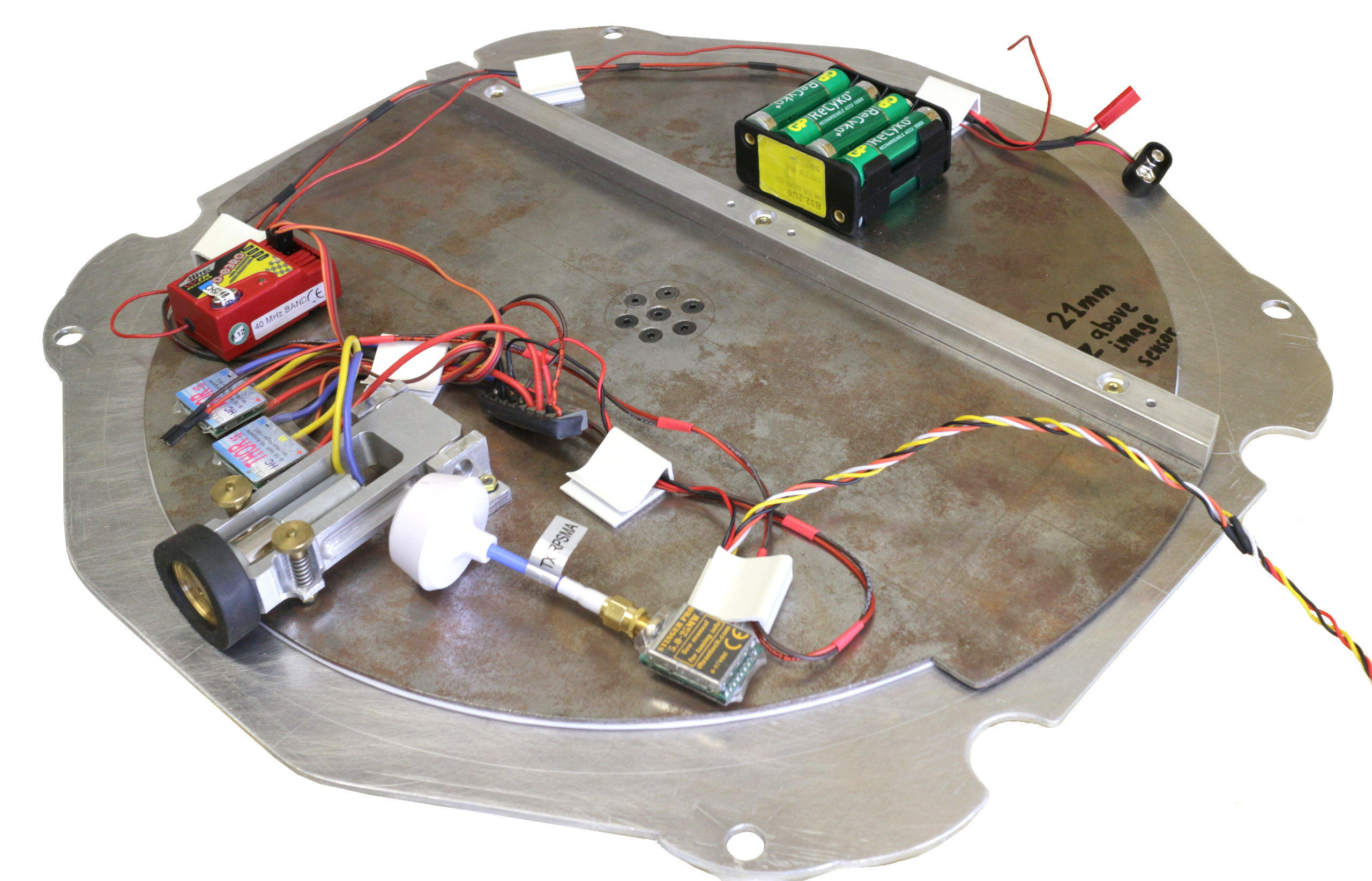
The optical table is made out of a mm alloy plate, which bolts on top of FACT’s image sensor, and a mm steel disc on top of this.
The surface of the optical table is only mm above the image sensor plane and has a profile rail to align its components.
The pseudo optical axis is mm above the image sensor plane ( of FACT’s image sensor diameter).
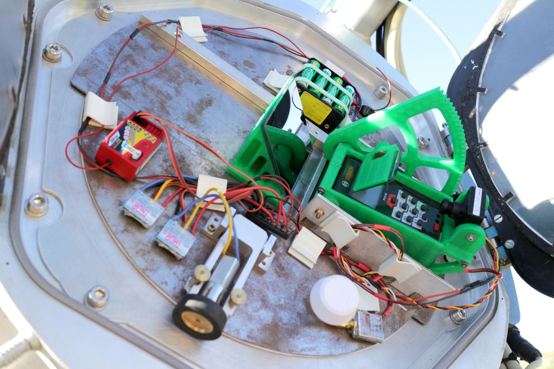
The -joint between the plates is actuated by a motorized rubber wheel which is mounted on the top steel plate while running on the bottom alloy plate, see Figure 7.
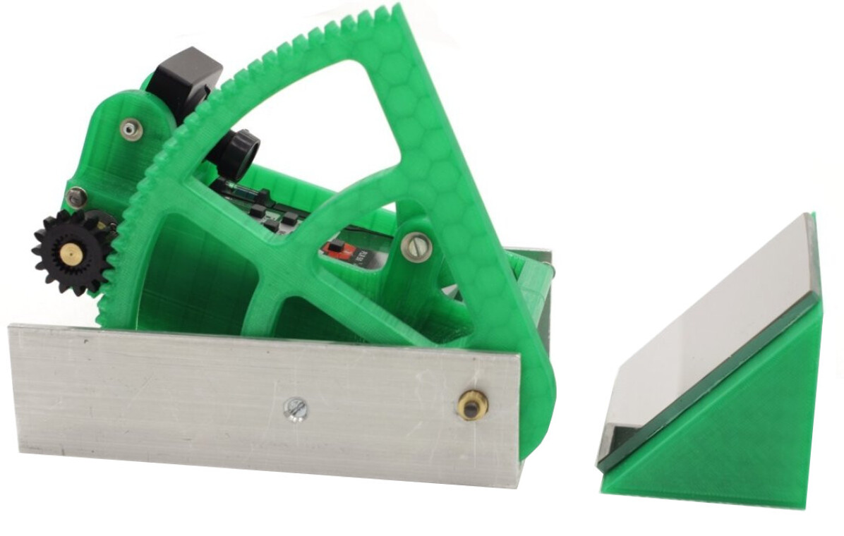
The second actuated -joint of the LDM is made out of a lightweight 3D printed plastic enclosure for the LDM which includes a small actuator gear running along on a big 3D printed arc, see Figure 9.
4 MIPOD alignment for FACT
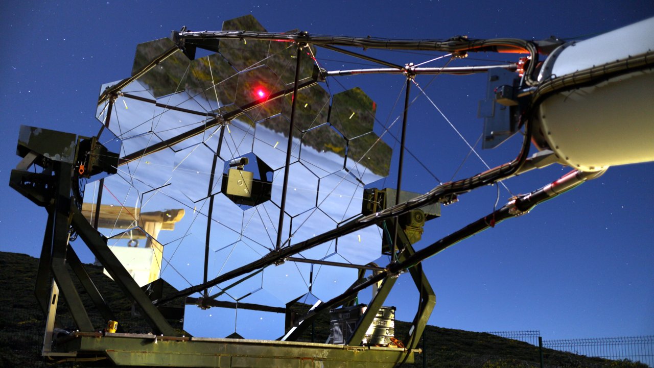
The First Geiger-mode Avalanche Cherenkov Telescope (FACT) is located on Canary island La Palma, Spain. It inherited its mount and the mirror facets from HEGRA, see Figure 10. While pioneering silicon photomultipliers for IACTs, FACT is monitoring gamma ray bright blazars such as Mrk 421 and Mrk 501. FACT has a focal length of m and 30 identical, hexagonally shaped, and spherically curved mirror facets. The maximum outer aperture diameter is m. Its image sensor spans field of view, or cm in diameter respectively and has 1440 pixels which span or mm each. Typical air-showers records contain about photon equivalents spread over about shower pixels.
To redesign the FACT reflector with a hybrid Davies Cotton and parabola geometry, we use our MIPOD alignment. Further, we use MIPOD to measure the positions of the mirror facets before and after the modification so that FACT’s IACT simulation is up to date.
4.1 Installation and operation
The optical table of our MIPOD implementation is temporarily bolted on top of the image sensor of FACT, see Figure 11. While observing the laser beam moving along the mirror facet surfaces, Figure 10, the MIPOD operator controls the and actuators of the LDM via an analog radio remote control. The distance is measured continuously and displayed to the operator on a monitor. Because of a former refurbishing process, most of the mirror facets on FACT have a dull spot of about cm in diameter in the center of their surfaces which helped the LDM to receive its scattered beam. On the mirror facets without such dull spots, we attached dull stickers in the centers to run the LDM reliably.
5 Results
First, our MIPOD implementation measured that the mirror facets positions deviated by up to cm and cm (0.5% of the focal length ) from their target positions for the Davies Cotton geometry. This deviation is now taken into account in our IACT simulation for this epoch. Second, we aligned all the mirror facet positions in to their new target positions to form an equally mixed Davies Cotton and parabola hybrid geometry.
6 Conclusion
Our Mirror Position Determination (MIPOD) implementation enabled us to reliably redesign the segmented imaging reflector of FACT by measuring the facet positions in a very direct way relative to the image sensor plane. The optical table proved to be versatile as we used it also for our Normalized and Asynchronous Mirror Orientation Determination (NAMOD) [14]. Operating a vintage telescope mount and refurbished mirror facets ourselves, we believe that the upcoming long term instruments, like the Cherenkov Telescope Array (CTA) [9], will profit from a MIPOD system to keep their telescopes and telescope simulations as powerful and up to date as possible through out all the repairs and upgrades during the long expected lifetime.
Acknowledgments
The important contributions from ETH Zurich grants ETH-10.08-2 and ETH-27.12-1 as well as the funding by the German BMBF (Verbundforschung Astro- und Astroteilchenphysik) and HAP (Helmoltz Alliance for Astro- particle Physics) are gratefully acknowledged. We are thankful for the very valuable contributions from E. Lorenz, D. Renker and G. Viertel during the early phase of the project. We thank the Instituto de Astrofisica de Canarias allowing us to operate the telescope at the Observatorio del Roque de los Muchachos in La Palma, the Max-Planck-Institut fuer Physik for providing us with the mount of the former HEGRA CT3 telescope, and the MAGIC collaboration for their support.
References
References
- [1] T. Hara, T. Kifune, Y. Matsubara, Y. Mizumoto, Y. Muraki, S. Ogio, T. Suda, T. Tanimori, M. Teshima, T. Yoshikoshi, et al., A 3.8 m imaging Cherenkov telescope for the TeV gamma-ray astronomy collaboration between Japan and Australia, Nucl. Instrum. Meth. A 332 (1) (1993) 300–309.
- [2] D. A. Lewis, Optical characteristics of the Whipple observatory Tev gamma-ray imaging telescope, Experimental Astronomy 1 (4) (1990) 213–226.
- [3] A. Barrau, R. Bazer-Bachi, E. Beyer, H. Cabot, M. Cerutti, L. Chounet, G. Debiais, B. Degrange, H. Delchini, J. Denance, et al., The CAT imaging telescope for very-high-energy gamma-ray astronomy, Nucl. Instrum. Meth. A 416 (2) (1998) 278–292.
- [4] J. Holder, R. Atkins, H. Badran, G. Blaylock, S. Bradbury, J. Buckley, K. Byrum, D. Carter-Lewis, O. Celik, Y. Chow, et al., The first VERITAS telescope, Astroparticle Physics 25 (6) (2006) 391–401.
- [5] K. Bernlöhr, O. Carrol, R. Cornils, S. Elfahem, P. Espigat, S. Gillessen, G. Heinzelmann, G. Hermann, W. Hofmann, D. Horns, et al., The optical system of the HESS imaging atmospheric Cherenkov telescopes. Part I: layout and components of the system, Astroparticle Physics 20 (2) (2003) 111–128.
- [6] R. Cornils, K. Bernlöhr, G. Heinzelmann, W. Hofmann, M. Panter, The optical system of the HESS II telescope, in: International Cosmic Ray Conference, Vol. 5, 2005, p. 171.
- [7] C. Baixeras, M. Collaboration, et al., The MAGIC telescope, Nuclear Physics B-Proceedings Supplements 114 (2003) 247–252.
- [8] H. Anderhub, M. Backes, A. Biland, V. Boccone, I. Braun, T. Bretz, J. Buß, F. Cadoux, V. Commichau, L. Djambazov, et al., Design and operation of FACT – the First G-APD Cherenkov Telescope, Journal of Instrumentation 8 (06) (2013) P06008.
- [9] B. S. Acharya, M. Actis, T. Aghajani, G. Agnetta, J. Aguilar, F. Aharonian, M. Ajello, A. Akhperjanian, M. Alcubierre, J. Aleksić, et al., Introducing the CTA concept, Astroparticle Physics 43 (2013) 3–18.
- [10] Y. Igor, et al., Imaging Camera and Hardware of Tunka-IACT, in: Proceedings of the 34th ICRC, Vol. 986, 2015.
- [11] M. L. Ahnen, D. Baack, M. Balbo, M. Bergmann, A. Biland, et al., Bokeh Mirror Alignment for Cherenkov Telescopes, submitted to Astroparticle Physics.
- [12] F. Arqueros, G. Ros, G. Elorza, D. Garcia-Pinto, A technique for the optical characterization of imaging air-Cherenkov telescopes, Astroparticle Physics 24 (1) (2005) 137–145.
- [13] A. McCann, D. Hanna, J. Kildea, M. McCutcheon, A new mirror alignment system for the VERITAS telescopes, Astroparticle Physics 32 (6) (2010) 325–329.
- [14] M. L. Ahnen, D. Baack, M. Balbo, M. Bergmann, A. Biland, et al., Normalized and Asynchronous Mirror Alignment for Cherenkov Telescopes, submitted to Astroparticle Physics.
- [15] A. Biland, M. Garczarczyk, H. Anderhub, V. Danielyan, D. Hakobyan, E. Lorenz, R. Mirzoyan, M. Collaboration, The Active Mirror Control of the MAGIC Telescope, in: Proceedings of the 30th ICRC, Vol. 533, 2007, pp. 1353–1356.
- [16] V. Fonseca, Status and Results from the HEGRA Air Shower Experiment, Astrophysics and space science 263 (1-4) (1998) 377–380.
- [17] J. M. Davies, E. S. Cotton, Design of the Quartermaster Solar Furnace, Solar Energy 1 (2) (1957) 16–22.
- [18] M. Noethe, et al., FACT – Calibration of Imaging Atmospheric Cherenkov Telescopes with Muon Rings, in: Proceedings of the 34th ICRC, Vol. 733, 2015.
- LDM
- Laser Distance Meter
- FACT
- First Geiger-mode Avalanche Cherenkov Telescope
- IACT
- Imaging Atmospheric Cherenkov Telescope
- MIPOD
- Mirror Position Determination
- NAMOD
- Normalized and Asynchronous Mirror Orientation Determination
- CTA
- Cherenkov Telescope Array