Failsafe Mechanism Design of Multicopters Based on Supervisory Control Theory
Abstract
In order to handle undesirable failures of a multicopter which occur in either the pre-flight process or the in-flight process, a failsafe mechanism design method based on supervisory control theory is proposed for the semi-autonomous control mode 111Most multicopters have two high-level control modes: semi-autonomous control and full-autonomous control. Many open source autopilots support both modes. The semi-autonomous control mode implies that autopilots can be used to stabilize the attitude of multicopters, and also they can help multicopters to hold the altitude and position. Under such a mode, a multicopter will be still under the control of remote pilots. On the other hand, the full-autonomous control mode implies that the multicopter can follow a pre-programmed mission script stored in the autopilot which is made up of navigation commands, and also can take off and land automatically. Under such a mode, remote pilots on the ground only need to schedule the tasks [1].. Failsafe mechanism is a control logic that guides what subsequent actions the multicopter should take, by taking account of real-time information from guidance, attitude control, diagnosis, and other low-level subsystems. In order to design a failsafe mechanism for multicopters, safety issues of multicopters are introduced. Then, user requirements including functional requirements and safety requirements are textually described, where function requirements determine a general multicopter plant, and safety requirements cover the failsafe measures dealing with the presented safety issues. In order to model the user requirements by discrete-event systems, several multicopter modes and events are defined. On this basis, the multicopter plant and control specifications are modeled by automata. Then, a supervisor is synthesized by monolithic supervisory control theory. In addition, we present three examples to demonstrate the potential blocking phenomenon due to inappropriate design of control specifications. Also, we discuss the meaning of correctness and the properties of the obtained supervisor. This makes the failsafe mechanism convincingly correct and effective. Finally, based on the obtained supervisory controller generated by TCT software, an implementation method suitable for multicopters is presented, in which the supervisory controller is transformed into decision-making codes.
Keywords: Multicopter, failsafe mechanism, supervisory control.
I Introduction
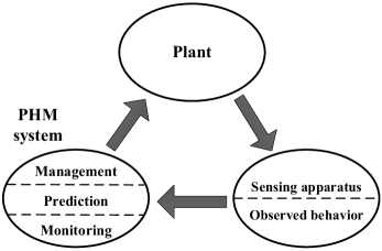
Multicopters are well-suited to a wide range of mission scenarios, such as search and rescue [2], [3], package delivery [4], border patrol [5], military surveillance [6] and agricultural production [7]. In either pre-flight process or in-flight process, multicopter failures cannot be absolutely avoided. These failures may abort missions, crash multicopters, and moreover, injure or even kill people. In order to handle undesirable failures in industrial systems, a technique named Prognostics and Health Management (PHM) is presented [8]. As shown in Figure 1, an integrated PHM system generally contains three levels: monitoring, prediction and management [9]. On the one hand, the monitoring and prediction levels assess the quantitative health of the studied system, where some quantitative indices are introduced to measure system health, such as residuals [10]-[12], data features [13], [14] and reliability-based indices [15]-[18]. On the other hand, the management level imports the quantitative health results from the monitoring and prediction levels, and then responds to meet qualitative safety or health requirements. In our previous paper [19], multicopter health is quantitatively evaluated in the face of actuator failures. This paper studies a safety decision-making logic by Supervisory Control Theory (SCT) to guarantee flight safety from a qualitative perspective.
In the framework of multicopters, guidance, attitude control, PHM, and other low-level subsystems work together under the coordination of a high-level decision-making module [20]. In this module, a failsafe mechanism is an important part. It is a control logic that receives information from all subsystems to decide the best flight maneuver from a global perspective, and send flight instructions to low-level subsystems [21]. However, current academic literature covering failure-related topics of multicopters mainly focuses on fault detection techniques [22]-[26] and fault-tolerant control algorithms [27]-[32], which belong to a study of low-level subsystems. For the study of the high-level decision-making module, most research focuses on path planning [33]-[35] and obstacle avoidance [36], [37] of an individual multicopter, or PHM-based mission allocation of a multicopter team [6], [38], [39]. However, few studies have focused on the failsafe mechanism design of an individual multicopter subject to multiple potential failures. References [40], [41] proposed an emergency flight planning for an energy-constrained situation. Reference [42] proposed a failsafe design for an uncontrollable situation. Reference [43] designed multiple failsafe measures dealing with different anomalies of unmanned aerial vehicles. Nevertheless, that research only considers certain ad-hoc failsafe mechanisms for certain faults or anomalies, and so far does not present a comprehensive failsafe mechanism for a multicopter. In current autopilot products (for example, DJI autopilot [44] and ArduPilot [45]), there exist comprehensive failsafe mechanisms to cope with communication, sensor and battery failures, but such mechanisms are either proprietary, or can be accessed only in part. Moreover, as far as the authors know, these failsafe mechanisms are mainly developed and synthesized according to engineering experience. As a result, such a development process lacks a theoretical foundation; this will inevitably lead to man-made mistakes, logical bugs and an incomplete treatment. Motivated by these, this paper first summarizes safety issues and user requirements for multicopters in the semi-autonomous control manner as comprehensively and systematically as possible, and then uses SCT of Discrete-Event Systems (DES) to design a failsafe mechanism of multicopters.
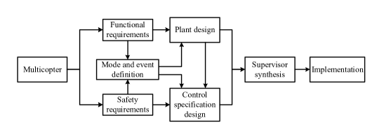
SCT [46], [47], also known as Ramadge-Wonham (RW) theory, is a method for synthesizing supervisors that restrict the behavior of a plant such that as much as possible of the given control specifications are fulfilled and never violated. Currently, SCT has been developed with a solid theoretical foundation [48]-[50], and it has been successfully applied to practical systems such as flexible manufacturing systems [51]-[53]. Thus, this paper formalizes the problem of failsafe mechanism design as a DES control problem. The solution procedure is shown in Figure 2. In order to obtain the expected failsafe mechanism, the following steps are performed: 1) define related modes and events by studying the user requirements (including functional and safety requirements); 2) model the multicopter plant by transforming the functional requirements to an automaton with defined modes and events; 3) analyze the safety requirements by taking the defined modes and events into account, and transform the safety requirements to automata as control specifications; 4) synthesize the supervisor by TCT software; 5) implementation the failsafe mechanism based on the obtained supervisor.
The contributions of the paper mainly lie in two aspects.
-
•
First, this paper introduces SCT into a new application area. The proposed SCT based method in this paper is a scientific method with solid theoretical foundation to design the failsafe mechanism of multicopters. In the field of aircraft engineering, especially of multicopters and drones, traditional design methods are based on engineering experience. The failsafe mechanism obtained by these methods may be problematic (for example, the failsafe mechanism may contain unintended deadlocks), especially when multiple safety issues are taken into account. Compared to existing empirical design methods, the proposed method can guarantee the correctness and effectiveness of the obtained failsafe mechanism owing to the properties of supervisors. This is an urgent need for multicopter designers and manufacturers.
-
•
Second, for the application of SCT, this paper emphasizes the modeling process of the plant and control specifications with a practical application, rather than developing a new theory of SCT. We believe this work is important to both the development of SCT research and practical engineering, because SCT is presented with complex mathematical terminology and theory which many engineers may not understand. Motivated by this, this paper presents the procedure of applying SCT to an engineering problem, from requirements described textually, to specificarions in form of automata, then to a synthesized supervisor and finally to implementation on a real-time flight simulation platform of quadcopters developed by MATLAB. In addition, we present three examples to demonstrate the potential blocking phenomenon due to inappropriate design of control specifications. From the perspective of practitioners, this paper can be a guide for engineers, who are not familiar with SCT, to solve their own problems in their own projects by SCT and related software.
The remainder of this paper is organized as follows. Section II presents preliminaries of SCT for the convenience of presenting the subsequent sections. Section III lists some relevant safety issues of multicopters. Also, user requirements including functional requirements and safety requirements are textually described. In order to transform the user requirements to automata, several multicopter modes and events are defined in Section IV. On this basis, a detailed modeling process of the multicopter plant and control specifications is presented in Section V, where functional requirements determine a general multicopter plant, and safety requirements are modeled as control specifications. Then, TCT software is used to perform the process of supervisor synthesis. Section VI illustrates three examples to demonstrate some possible reasons leading to a problematic supervisor, and gives a brief discussion about the scope of applications and properties of the used method. Section VII shows an implementation process of the proposed failsafe mechanism on the platform of MATLAB and FlightGear. Section VIII presents our conclusion and suggests future research.
II Preliminaries of Supervisory Control Theory
As SCT is well established, readers can refer to textbooks [46], [55], [56] for detailed background and knowledge. This section only reviews some basic concepts and notation.
In RW theory [46], [47], the formal structure of DES is modeled by an automaton (generator)
| (1) |
where is the finite state set; is the finite event set (also called an alphabet); is the (partial) transition function; is the initial state; is the subset of marker states. Let denote the set of all finite strings, including the empty string . In general, is extended to , and we write to mean that is defined. The closed behavior of is the language
and the marked behavior is
A string is a prefix of a string , written , if there exists such that . The prefix closure of is . We say that is nonblocking if . The three equivalent meanings of “nonblocking” are 1) the system can always reach a marker state from every reachable state; 2) every string in the closed behavior can be extended to a string in the marked behavior; 3) every physically possible execution can be extended to completing distinguished tasks.
The usual way to combine several automata into a single, more complex automaton is called synchronous product. For two automata , the synchronous product of and , denoted by , is constructed to have marked behavior and closed behavior [46, Chapter 3.3]. The synchronous product of more than two automata can be constructed similarly.
For a practical system, the plant can be modeled as an automaton . The desired behavior of the controlled system is determined by a control specification, also modeled as an automaton . Both the plant and the control specification may be the synchronous product of many smaller components.
For supervisory control, the alphabet is partitioned as
where is the subset of controllable events that can be disabled by an external supervisor, and is the subset of uncontrollable events that cannot directly be prevented from occurring. Here and are disjoint subsets. A supervisory controller (supervisor) forces the plant to respect the control specification by disabling certain controllable events that are originally able to occur in the plant.
To synthesize a satisfactory supervisor, SCT provides a formal method for theoretically solving the typical supervisory control problem [54]: Given a plant over alphabet and control specification , find a maximally permissive supervisor such that the controlled system is non-blocking and meets the control specification . That is satisfies
| (2) |
where means the supremal controllable sublanguage of . Equation (2) means that the supervisor never violates the control specification . Here, is a monolithic (namely fully centralized) supervisor [46, Chapter 4.6]. If there exist several control specifications, the supervisor can be also designed in a decentralized framework. Decentralized supervisory control assigns a separate specialized supervisor to satisfy each control specification . For each control specification , a decentralized supervisor is computed in the same way as for a monolithic supervisor. Then, all the decentralized supervisors work together to meet the control specification . Here, if the synthesized supervisors are blocking, a coordinator is required to make the supervisors nonblocking. The main advantage of the decentralized supervisory control framework is that the synthesized supervisors are relatively small-scale, and are easier to understand, maintain and change.
III Safety Issues and User Requirements
This section lists some relevant safety issues of multicopters. Also, user requirements including functional requirements and safety requirements are textually described.
III-A Safety issues
Major types of multicopter failures that may cause accidents will be introduced. Here, three types of failures are considered, including communication breakdown, sensor failure and propulsion system anomaly.
-
•
Communication breakdown. Communication breakdown mainly refers to a contact anomaly between the Remote Controller (RC) transmitter and the multicopter, or between the Ground Control Station (GCS) and the multicopter. In this paper, for simplicity, only RC is considered.
-
•
Sensor failure. Sensor failure mainly implies that a sensor on the multicopter cannot accurately measure related variables, or cannot work properly. This paper considers the sensor failures including barometer failure, compass failure, GPS failure, Inertial Navigation System (INS) failure.
-
•
Propulsion system anomaly. Propulsion system anomaly mainly refers to battery failure and propulsor failure caused by Electronic Speed Controllers (ESCs), motors or propellers.
More information about safety issues can be found in the book [1].
III-B User requirements
From the commercial perspective of customers and users, a multicopter product is required to have general functions as a rotorcraft, and also be capable of coping with the relevant safety issues. Thus, functional requirements and safety requirements are listed in Tables 1-4, respectively. They are summarized by referring the material from [45] and the authors’ knowledge and engineering experience.
III-B1 Functional requirements
The following functional requirements describe what behavior the multicopter is able to perform.
Table 1. Functional requirements
|
III-B2 Safety requirements
The safety requirements restrict what action the user wants the multicopter to perform under specific situations when it is on the ground, in flight, or in process of returning and landing.
Table 2. Safety requirements on ground
|
Table 3. Safety requirements in flight
|
Table 4. Safety requirements on returning and landing
|
IV Multicopter Mode and Event Definition
In order to transform the user requirements to automata, several multicopter modes and events are defined in this section.
IV-A Multicopter mode
Referring to [45], the whole process from taking off to landing of multicopters is divided into eight multicopter modes. They form the basis of the failsafe mechanism.
-
•
POWER OFF MODE. This mode implies that a multicopter is out of power. In this mode, the remote pilot can (possibly) disassemble, maintain and replace the hardware of a multicopter.
-
•
STANDBY MODE. When a multicopter is connected to the power module, it enters a pre-flight status. In this mode, the multicopter is not armed, and the remote pilot can arm the multicopter manually. Afterwards, the multicopter will perform a safety check and then transit to the next mode according to the results of the safety check.
-
•
GROUND-ERROR MODE. This mode indicates that the multicopter has a safety problem. In this mode, the buzzer will turn on an alarm to alert the remote pilot that there exist errors in the multicopter.
-
•
LOITER MODE. Under this mode, the remote pilot can use the control sticks of the RC transmitter to control the multicopter. Horizontal location can be adjusted by the roll and pitch control sticks. When the remote pilot releases the control sticks, the multicopter will slow to a stop. Altitude can be controlled by the throttle control stick. The heading can be set with the yaw control stick. When the remote pilot releases the roll, pitch and yaw control sticks and pushes the throttle control stick to the mid-throttle deadzone, the multicopter will automatically maintain the current location, heading and altitude.
-
•
ALTITUDE-HOLD MODE. Under this mode, a multicopter maintains a consistent altitude while allowing roll, pitch and yaw to be controlled normally. When the throttle control stick is in the mid-throttle deadzone, the throttle is automatically controlled to maintain the current altitude and the attitude is also stabilized but the horizontal position drift will occur. The remote pilot will need to regularly give roll and pitch commands to keep the multicopter in place. When the throttle control stick goes outside the mid-throttle deadzone, the multicopter will descend or climb depending upon the deflection of the control stick.
-
•
STABILIZE MODE. This mode allows a remote pilot to fly the multicopter manually, but self-levels the roll and pitch axes. When the remote pilot releases the roll and pitch control sticks, the multicopter automatically stabilizes its attitude but position drift may occur. During this process, the remote pilot will need to regularly give roll, pitch and throttle commands to keep the multicopter in place as it might be pushed around by wind.
-
•
RETURN-TO-LAUNCH (RTL) MODE. Under this mode, the multicopter will return to the base location from the current position, and hover there.
-
•
AUTOMATIC-LANDING (AL) MODE. In this mode, the multicopter realizes automatic landing by adjusting the throttle according to the estimated height 333Even if the barometer fails, the height estimation is acceptable within a short time. Similarly, the other estimates generated by filters could continue to be used for a short time, even if related sensors fail..
IV-B Event definition
Three types of events are defined here: Manual Input Events (MIEs), Mode Control Events (MCEs) and Automatic Trigger Events (ATEs). The failsafe mechanism detects the occurrence of MIEs and ATEs, and uses MCEs to decide which mode the multicopter should stay in or switch to. Here, MIEs and MCEs are controllable, while ATEs are uncontrollable in the sense of SCT.
IV-B1 MIEs
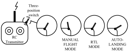
MIEs are instructions from the remote pilot sent through the RC transmitter. This part defines eight MIEs as shown in Table 5.
Table 5. MIE definition
|
Here, MIE6, MIE7 and MIE8 are realized by a three-position switch (namely the flight mode switch) on the RC transmitter as shown in Figure 3.
IV-B2 MCEs
MCEs are instructions from multicopter’s autopilot. As shown in Table 6, these events will control the multicopter to switch to a specified mode.
Table 6. MCE definition
|
IV-B3 ATEs
ATEs are independent of the remote pilot’s operations. As shown in Table 7, these events contain the health check results of onboard equipment and sensor measurements of the multicopter status.
Table 7. ATE definition
|
Here, note that this paper assumes the health check of equipment above can be performed by effective fault diagnosis and health evaluation methods. For simplified presentation, the statements of “check result of” and “measured” are omitted in the subsequent sections.
Remark 1. MCEs are defined to guarantee the controllability of the plant, because supervisory control restricts the behavior of a plant such that the given control specifications are fulfilled and as much as possible never violated, by enabling or disabling controllable events in the plant. According to safety requirements, the user declares which mode the multicopter should enter. This leads to the definition of controllable events related to mode transitions, namely MCEs.
V Failsafe Mechanism Design
The failsafe mechanism uses multicopter modes and switch conditions among them to make multicopters satisfy the user’s safety requirements. In this section, functional requirements are used to model a multicopter plant automaton with defined multicopter modes and events. Then, from the safety requirements, multiple control specifications are represented by automata. These control specifications should indicate the preferable failsafe measures consistent with the textually described safety requirements. After the plant and control specifications have been obtained, the supervisor is synthesized by using monolithic supervisory control.
V-A Multicopter plant modeling
V-A1 Modeling principles
Modeling the multicopter plant is to mathematically describe what behavior the multicopter is able to perform with an automaton transformed from functional requirements. In this paper, the modeling principles of the multicopter plant include: i) modeling from a simple schematic diagram to a comprehensive automaton model; 2) modeling from the ‘on ground’ component to the ‘in air’ component; 3) events of each transition modeled mutually exclusively. Figure 4 depicts a schematic diagram of the ‘on ground’ component and ‘in air’ component of the multicopter plant, respectively. The schematic diagram lists all modes which the multicopter possibly enters, after a series of MIEs and ATEs occur.
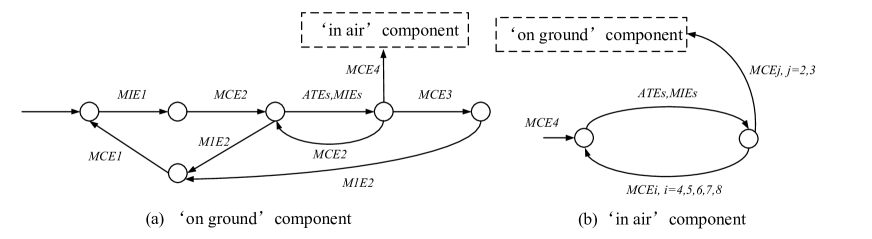
V-A2 Model details
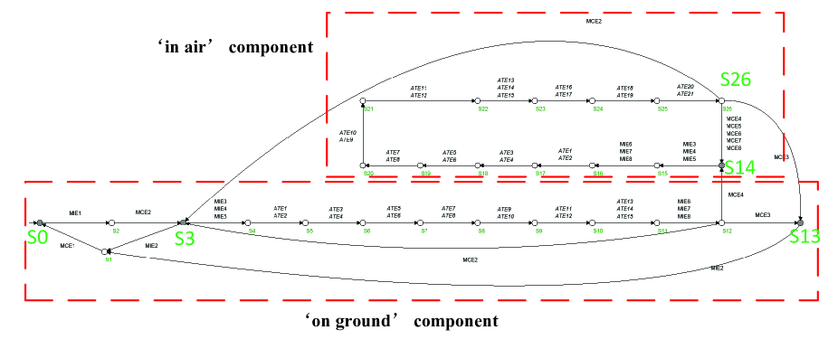
By extending the above schematic diagrams with detailed events and transitions, the plant is described by an automaton as shown in Figure 5. It describes the basic function of a multicopter. Specifically, Plant contains 27 states (S0-S26), 37 events and 63 transitions. Here, the states SSSS14 are marked as accepting states. The state S0 represents POWER OFF MODE; the state S3 represents STANDBY MODE; the state S13 represents GROUND-ERROR MODE; the state S14 integrates other multicopter modes. Plant can be divided into two parts: one (consists of states S0-S14 and transitions among them) describes the multicopter behavior on the ground (‘on ground’ component), and the other one (consists of states S3,S12-S26 and transitions among them) describes the behavior during flight (‘in air’ component). These correspond to the schematic diagram shown in Figure 4.
V-B Control specification design
V-B1 Modeling principle
In this part, control specifications are designed to restrict the behavior of Plant according to the description of the safety requirements. In order to obtain a correct and non-blocking supervisor, the control specifications must cover all possible strings (enable desirable strings and disable the others) in the plant, and the control specifications must have no conflict among themselves.
V-B2 Control specification design ‘on ground’
Through a study of safety requirements, it can be seen that SR1 describes the intended failsafe measure when the multicopter is on the ground. In other words, SR1 restricts what action the user wants the multicopter to perform under specific situations when it is on the ground. Thus, we design a control specification to cover all possible strings in the ‘on ground’ component of Plant. The requirements given in Tables 1-3 are different from the designed specifications. The former is textually and informally described, whereas, based on which, the latter is designed formally described in form of automaton. Several requirements may be described by one specification, or one requirement may be described by several specifications.
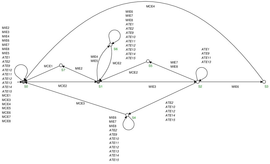
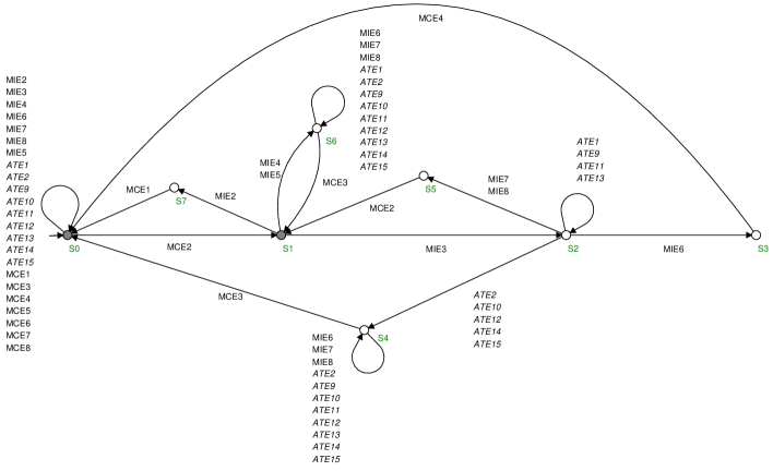
In safety requirement SR1, the user lists the required conditions for a successful arm. In order to model it with an automaton, the key is to split the branches in the ‘on ground’ component of Plant, and enable only one mode which the user expects the multicopter to switch to. Following this principle, a control specification named Specification 1 is designed as shown in Figure 6. It contains 8 states (S0-S7), 24 events and 68 transitions. Here, the states SS1 are marked as accepting states. The state S1 represents STANDBY MODE, and the state S0 integrates other multicopter modes. Here, two points need to be noted:
i) The selfloops on the state SSS6 are used to guarantee that the irrelevant events will not interrupt the event sequence presented in Plant, and not influence the occurrence of other control specifications.
ii) SR1 itself is textually and informally described. It does not mention which mode the multicopter should enter, if it cannot be successfully armed. Furthermore, it does not take all possible strings into consideration. In this case, during the design of control specifications, it is required to appropriately infer the user’s potential intention, and add the omitted part to guarantee that the control specification covers all possible strings in the ‘on ground’ component of Plant.
V-B3 Control specification design ‘in ground’ (Specification 7)
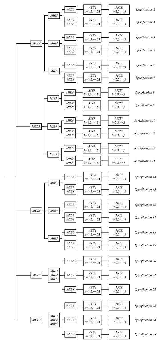
For the ‘in air’ component of Plant, safety requirements SR2-SR13 restrict what action the user wants the multicopter to perform under specific situations when it is in air. Thus, we design 24 control specifications to cover all possible strings in the ‘in air’ component of Plant. The traversal relation between the designed control specifications and the structure of the ‘in air’ component of Plant is shown in Figure 7.
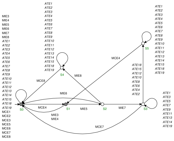
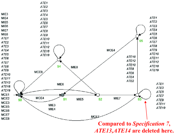
Here, because of limitation of space, we take Specification 7 as an example to demonstrate the design of control specifications for the ‘in air’ component of Plant. This control specification is obtained by transforming “safety requirements SR7 and SR8” to an automaton model. As shown in Figure 8, Specification 7 contains 6 states (S0-S5), 31 events and 91 transitions. Here, the states SS1 are marked as accepting states. The state S1 represents LOITER MODE, and the state S0 integrates other multicopter modes. The details of other control specifications are presented in the support material available in http://rfly.buaa.edu.cn/resources.
V-C Supervisor synthesis on TCT software
The algorithms and operations in this part are performed on TCT software. In order to synthesize a supervisor by TCT software, the modeled multicopter plant and designed control specifications are first input. The multicopter plant is named as “PLANT”, and the 25 control specifications are named as “”, . The input process is shown in http://rfly.buaa.edu.cn/resources.
V-C1 Control specification completion
Here, note that PLANT contains 37 events, while the number of events in each is less than 37 (i.e. the alphabet of each is different from that of PLANT). This is because the given textual safety requirements only emphasize the events we are concerned with and ignore the remaining events. For supervisory control, the alphabet of each should be equal to the alphabet of PLANT. Thus, the control specification should be completed by the following TCT instructions:
where is a selfloop automaton containing all events in the alphabet of PLANT. Then, for each , we have
Here, the events present in PLANT but not in are added into in form of selfloops.
V-C2 Supervisor synthesis
In the monolithic supervisory control framework, all the control specifications should be synchronized into a monolithic one. That is
It turns out that is nonblocking, and contains 133 states and 2219 transitions. Then, a monolithic supervisor is synthesized by
The obtained supervisor is the expected failsafe mechanism. It contains 784 states, 37 events and 1554 transitions. There are 8 accepting states to be marked, which correspond respectively to 8 multicopter modes. Besides the monolithic supervisory control, the supervisor can also be synthesized by decentralized supervisory control, and a supervisor reduction process can also be carried out for an easier realization in practice. The synthesis is also carried out in the software Supremica with the result same to TCT. These source files are presented in http://rfly.buaa.edu.cn/resources.
VI Examples and Discussion
This section illustrates three examples to demonstrate some possible reasons leading to a problematic supervisor, and gives a brief discussion about the scope of applications and properties of the method.
VI-A Examples
The design of control specifications is a process to understand and re-organize the safety requirements. If the designer synthesizes a blocking supervisor, he must recheck the correctness of control specifications and make modifications. Here, we illustrate three examples demonstrating the blocking phenomenon due to inappropriate design of control specifications and conflicting safety requirements.
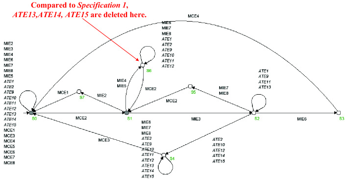
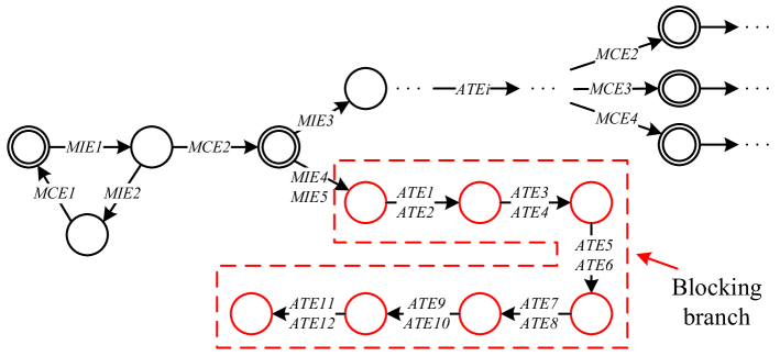
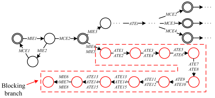
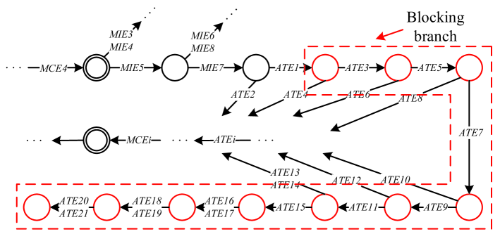
Example 1. The aim of this example is to show that missing information in control specification may lead to a blocking supervisor. In this example, we delete transitions “SATE13S6”, “SATE14S6” and “SATE15S6” in Specification 1. In this case, Specification 1 is changed to an automaton named Example 1 as shown in Figure 9. By replacing Specification 1 with Example 1, the supervisor is synthesized and turns out to be blocking. The blocking branch is depicted in Figure 10. The reason is that blocking occurs owing to the missing selfloops at state S6 in Example 1. The missing selfloops make the automaton “think” that events ATE13, ATE14 and ATE15 will not occur at state S6, while these events should occur in Plant. Thus, a blocking supervisor is synthesized. This means an uncertainty as to what should occur in the blocking point.
Example 2. The aim of this example is to show that conflict in control specifications will lead to a blocking supervisor. In this example, we replace the transition “SMCE2S1” with a transition “SMCE3S1” in Specification 1. In this case, Specification 1 is changed to an automaton named Example 2 as shown in Figure 11. By adding Example 2 to the whole control specification, the supervisor is synthesized and turns out to be blocking. The blocking branch is depicted in Figure 12. The reason that blocking occurs is the conflict between Specification 1 and Example 2. Specification 1 indicates a transition “SMCE2S1”, while Example 2 has a transition “SMCE3S1”. This conflict will “confuse” the supervisor, and make it impossible to decide which transition should occur. Thus, a blocking supervisor is synthesized.
Example 3. The aim of this example is to show that conflict in user requirements will lead to a blocking supervisor. Assume we have a new safety requirement described as follows: “when the multicopter is flying, the multicopter can be manually switched to return to the base by the RC transmitter. This switch requires that the INS, GPS, barometer, compass and propulsors are all healthy. Otherwise, the switch cannot occur.” Then, this safety requirement is transformed to an automaton as shown in Figure 13. By adding Example 3 to the whole control specification, the supervisor is synthesized and turns out to be blocking. The blocking branch is depicted in Figure 14. The reason that blocking appeared is the conflict between the original SR7 and the newly presented safety requirement. In SR7, it indicates that “this switch requires that the INS, GPS, barometer, compass, propulsors are all healthy, and the battery’s capacity is able to support the multicopter to return to the base”. However, the new safety requirement does not restrict the condition of battery’s capacity. As in Example 2, this conflict leads to a blocking supervisor.
Remark 2. From the above examples, it can be seen that an incorrect failsafe mechanism might be obtained during the design process due to conflicting safety requirements or incorrect and inappropriate design of control specifications. The mistake might be introduced inadvertently, and the designer cannot easily detect the problem by using empirical design methods. However, by relying on the SCT-based method, we can check the correctness of the obtained failsafe mechanism, and make modifications if a problematic supervisor is generated. This is a big advantage of the proposed method over empirical design methods. Once a nonblocking supervisor is obtained, the resulting failsafe mechanism is logically correct, and able to deal with all relevant safety issues appearing during flight.
VI-B Discussion
This paper aims to study a method to guarantee the correctness in the design of the failsafe mechanism. Actually, correctness can be interpreted in two different ways. On the one hand, correctness can be explained as absolute safety, meaning that the multicopter can cope with all possible safety problems. On the other hand, correctness is defined as consistency between the obtained failsafe mechanism and safety requirements. Given a model and a control specification for an autonomous system, synthesis approaches can automatically generate a protocol (or strategy) for controlling the system that satisfies or optimizes the property. This process is named as “correct-by-design” [59]. In this domain, various formal methods and techniques, such as SCT and linear temporal logic, are used to design control protocol of autonomous systems, including autonomous cars [60], aircraft [61]-[63] and swarm robots [64]. Similar to the above literature, in this paper, we focus on the meaning of correctness that all requirements can be correctly satisfied. With a precise description of both the multicopter and its correct behavior, the proposed method allows a failsafe mechanism that guarantees the correct behavior of the system to be automatically designed.
Here, the generated supervisor by SCT satisfies the following properties:
i) Deterministic. This property has two aspects. First, there exists no situation that one event triggers a transition from a single source state to different target states in the obtained supervisor. This is a necessary condition for a deterministic automaton. However, this situation might occur due to man-made mistakes in an empirical failsafe mechanism design. Second, after occurrence of MIEs and ATEs, SCT can guarantee that only one MCE is enabled by disabling other MCEs due to deliberate design of control specifications. In this case, after occurrence of certain MIEs and ATEs, the mode which the multicopter should enter is deterministic.
ii) Nonconflicting [46, Chapter 3.6]. None of the control specifications conflict with any others. If there exist conflicts, the supervisor will not be successfully synthesized, because SCT cannot decide which control specification is the user’s true intention. If so, the designer should check 1) the correctness of control specifications transforming from user requirements; or 2) the reasonableness of the user requirements.
iii) Nonblocking. The generated supervisor is nonblocking, which can be interpreted that all possible strings in Plant are considered (either enabled or disabled) in the supervisor. If there are some strings which are not considered in the control specifications, the marker states may not be reached in some branches from the initial state. Then, the obtained supervisor might be incomplete (even empty). This is because SCT cannot compute control due to incorrect user’s specifications. If so, the designer should modify the control specifications to make them consistent.
iv) Logical correctness. SCT is a mature and effective tool to be used in the area of decision-making. If the plant and control specifications are correctly modeled, the logic of the generated supervisor will correctly satisfy user requirements without introducing man-made mistakes and bugs.
VII Implementation and Simulation
Based on the obtained supervisory controller generated by TCT software or Supremica, an implementation method suitable for multicopter is presented, in which the supervisory controller is transformed into decision-making codes.
VII-A Failsafe mechanism implementation
On the one hand, we would want to avoid manual implementation of the calculated supervisors, since this may introduce errors and is also difficult for a complex case. On the other hand, we expect an easy way to generate an Application Programming Interface (API) function with events as the input and marked states as output so that it can be easily integrated into the existing program in flight boards. The information required from a synthesized supervisor is a transition matrix, which is an matrix where is the number of transitions in the synthesized supervisor (We have developed a function to export the transition matrix based on the output file of Supremica, available in http://rfly.buaa.edu.cn/resources). As shown in Table 8, in each row, it consists of a source state, a destination state and a triggered event. For example, if the multicopter is in source state and the triggered event is then the destination state will be . By taking the synthesized supervisor of multicopters as an example, it contains states, events and transitions. So, the transition matrix is an matrix. In fact, we only need to consider accepting states, namely POWER OFF MODE, STANDBY MODE, GROUND-ERROR MODE, LOITER MODE, ALTITUDE-HOLD MODE, STABILIZE MODE, RTL MODE and AL MODE. Based on them, corresponding low-level control actions exist. However, there exist many intermediate states in the transition matrix ( intermediate states for the considered multicopter), to which no control actions correspond. Therefore, after one decision period, the system must be in an accepting state. This is a major problem we need to solve. Fortunately, this is always true.
Table 8. Transition matrix
|
In practice, the events will be detected every for example, while the decision period may be . All triggered events are collected in every decision period. By recalling Figure 5, since the events in every transition are mutually exclusive, one and only one event must be triggered for any transition. As a result, the system does not stop at intermediate states after feeding in all detected events. For example, by recalling the ‘in air’ component in Figure 5, if the initial state is S14 and we collect the events MIE5, MIE6, ATE1, ATE3, ATE5, ATE7, ATE9, ATE11, ATE13, ATE16, ATE18, ATE20, then the system will go to S26 in Plant. Consequently, only one MCEi will be enabled by the autopilot according to the specifications. Therefore, the system will stop at an accepting state finally. For our case, the failsafe mechanism is implemented as shown in Table 9, where represents a decision-making time interval. Actually, the high-level decision-making should be a relatively slow process in practice. Thus, the failsafe mechanism implementation is not synchronized with the low-level flight control system.
Table 9. Decision-making logic implementation
|
VII-B Simulation
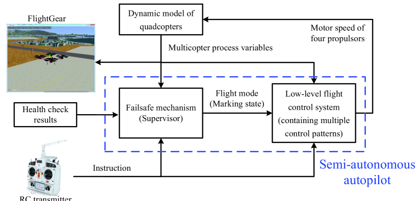
In this part, we put the failsafe mechanism into a real-time flight simulation platform of quadcopters developed by MATLAB. Although it is realized by MATLAB, this method is applicable to any programming language. The simulation diagram is shown in Figure 15. This simulation contains three main functions: i) the failsafe mechanism can determine the flight mode according to the health check result, instruction of RC transmitter and quadcopter status; ii) the remote pilot can fly the quadcopter through RC transmitter; iii) the flight status of quadcopter can be visually displayed by FlightGear. Thus, this simulation can be viewed as a semi-autonomous autopilot simulation of quadcopters. A video of this simulation is presented in https://www.youtube.com/watch?v=b1-K2xWbwF8&feature=youtu.be or http://t.cn/RXmhnu6. It contains three scenarios: i) the remote pilot manually controls the quadcopter to arm, fly, return to launch, and land; ii) anomalies of GPS, barometer, and INS are occurred during flight; iii) the connection of RC transmitter is abnormal during flight.
VIII Conclusions
This paper proposes an SCT based method to design a failsafe mechanism of multicopters. The modeling process of system plant and control specifications is presented in detail. The failsafe mechanism is obtained by synthesizing a supervisor in a monolithic framework. It ignores the detailed dynamic behavior underlying each multicopter mode. This is reasonable because the failsafe mechanism belongs to the high-level decision-making module of a multicopter, while the dynamic behavior can be characterized and controlled in the low-level flight control system. Also, we discuss the meaning of correctness and the properties of the obtained supervisor. This makes the failsafe mechanism convincingly correct and effective, demonstrating that the proposed method improves on purely empirical design methods. This paper deals with the health status of multicopter components in a qualitative manner. In future research, a quantitative health index will be added to extend the failsafe mechanism.
References
- [1] Quan Q. Introduction to multicopter design and control. Springer, Singapore, 2017.
- [2] Tomic T, Schmid K, Lutz P, et al. Toward a fully autonomous UAV: Research platform for indoor and outdoor urban search and rescue. IEEE robotics & automation magazine, 2012, 19(3): 46-56.
- [3] Goodrich M A, Morse B S, Gerhardt D, et al. Supporting wilderness search and rescue using a camera-equipped mini UAV. Journal of Field Robotics, 2008, 25(1-2): 89-110.
- [4] Agha-mohammadi A, Ure N K, How J P, et al. Health aware stochastic planning for persistent package delivery missions using quadrotors//2014 IEEE/RSJ International Conference on Intelligent Robots and Systems. IEEE, 2014: 3389-3396.
- [5] Girard A R, Howell A S, Hedrick J K. Border patrol and surveillance missions using multiple unmanned air vehicles//Decision and Control, 2004. CDC. 43rd IEEE Conference on. IEEE, 2004, 1: 620-625.
- [6] Bethke B, How J P, Vian J. Multi-UAV persistent surveillance with communication constraints and health management//AIAA Guidance, Navigation, and Control Conference (GNC). 2009.
- [7] Huang Y, Hoffman W C, Lan Y, et al. Development of a low-volume sprayer for an unmanned helicopter. Journal of Agricultural Science, 2015, 7(1): 148-153.
- [8] Kalgren P W, Byington C S, Roemer M J, et al. Defining PHM, a lexical evolution of maintenance and logistics//2006 IEEE Autotestcon. IEEE, 2006: 353-358.
- [9] Sheppard J W, Kaufman M A, Wilmer T J. IEEE standards for prognostics and health management. IEEE Aerospace and Electronic Systems Magazine, 2009, 24(9): 34-41.
- [10] Sun Z, Qin S J, Singhal A, et al. Control performance monitoring via model residual assessment//American Control Conference (ACC), 2012. IEEE, 2012: 2800-2805.
- [11] Gao Z, Cecati C, Ding S X. A survey of fault diagnosis and fault-tolerant techniques-Part I: fault diagnosis With model-based and signal-based approaches. IEEE Transactions on Industrial Electronics, 2015, 62(6): 3757-3767.
- [12] Wang G, Huang Z. Data-driven fault-tolerant control design for wind turbines with robust residual generator. IET Control Theory & Applications, 2015, 9(7): 1173-1179.
- [13] Henriquez P, Alonso J B, Ferrer M, et al. Review of automatic fault diagnosis systems using audio and vibration signals. IEEE Transactions on Systems, Man, and Cybernetics: Systems, 2014, 44(5): 642-652.
- [14] Soualhi A, Razik H, Clerc G, et al. Prognosis of bearing failures using hidden Markov models and the adaptive neuro-fuzzy inference system.IEEE Transactions on Industrial Electronics, 2014, 61(6): 2864-2874.
- [15] Xu Z, Ji Y, Zhou D. A new real-time reliability prediction method for dynamic systems based on on-line fault prediction. IEEE Transactions on Reliability, 2009, 58(3): 523-538.
- [16] Lu H, Kolarik W J, Lu H. Real-time performance reliability prediction. IEEE Transactions on Reliability, 2001, 50(4): 353-357.
- [17] Lu S, Lu H, Kolarik W J. Multivariate performance reliability prediction in real-time. Reliability Engineering & System Safety, 2001, 72(1): 39-45.
- [18] Zhao Z, Quan Q, Cai K Y. A profust reliability based approach to prognostics and health management. IEEE Transactions on Reliability, 2014, 63(1): 26-41.
- [19] Zhao Z, Quan Q, Cai K Y. A modified profust-performance-reliability algorithm and its application to dynamic systems. Journal of Intelligent & Fuzzy Systems, 2017, 32(1): 643-660.
- [20] Fisher J E, Lawrence D A, Zhu J J. Autocommander-a supervisory controller for integrated guidance and control for the 2nd generation reusable launch vehicle//AIAA Guidance, Navigation, and Control Conference and Exhibit. 2002: 5-8.
- [21] Arnaiz A, Ferreiro S, Buderath M. New decision support system based on operational risk assessment to improve aircraft operability. Proceedings of the Institution of Mechanical Engineers, Part O: Journal of Risk and Reliability, 2010, 224(3): 137-147.
- [22] Frangenberg M, Stephan J, Fichter W. Fast Actuator fault detection and reconfiguration for multicopters//AIAA Guidance, Navigation, and Control Conference. 2015: 1766.
- [23] Meskin N, Khorasani K, Rabbath C A. A hybrid fault detection and isolation strategy for a network of unmanned vehicles in presence of large environmental disturbances. IEEE Transactions on Control Systems Technology, 2010, 18(6): 1422-1429.
- [24] Freddi A, Longhi S, Monteriu A. A model-based fault diagnosis system for a mini-quadrotor//7th workshop on Advanced Control and Diagnosis. 2009: 19-20.
- [25] Freddi A, Longhi S, Monteri A, et al. Actuator fault detection and isolation system for an hexacopter//Mechatronic and Embedded Systems and Applications (MESA), 2014 IEEE/ASME 10th International Conference on. IEEE, 2014: 1-6.
- [26] Candido A S, Galvao R K H, Yoneyama T. Actuator fault diagnosis and control of a quadrotor//2014 12th IEEE International Conference on Industrial Informatics (INDIN). IEEE, 2014: 310-315.
- [27] Falconi G P, Holzapfel F. Adaptive fault tolerant control allocation for a hexacopter system//American Control Conference (ACC), 2016. American Automatic Control Council (AACC), 2016: 6760-6766.
- [28] Du G X, Quan Q, Cai K Y. Controllability analysis and degraded control for a class of hexacopters subject to rotor failures. Journal of Intelligent & Robotic Systems, 2015, 78(1): 143-157.
- [29] Dydek Z T, Annaswamy A M, Lavretsky E. Adaptive control of quadrotor UAVs: A design trade study with flight evaluations. IEEE Transactions on control systems technology, 2013, 21(4): 1400-1406.
- [30] Zhang Y, Jiang J. Integrated design of reconfigurable fault-tolerant control systems. Journal of Guidance, Control, and Dynamics, 2001, 24(1): 133-136.
- [31] Mueller M W, D’Andrea R. Relaxed hover solutions for multicopters: Application to algorithmic redundancy and novel vehicles. The International Journal of Robotics Research, 2015: 1-17.
- [32] Raabe C T, Suzuki S. Adaptive, Failure-tolerant control for hexacopters//AIAA Infotech @ Aerospace (I@A) Conference, ser. Guidance, Navigation, and Control and Co-located Conferences. American Institute of Aeronautics and Astronautics. 2013.
- [33] Bozhinoski D, Di Ruscio D, Malavolta I, et al. FLYAQ: enabling non-expert users to specify and generate missions of autonomous multicopters//Automated Software Engineering (ASE), 2015 30th IEEE/ACM International Conference on. IEEE, 2015: 801-806.
- [34] Yakovlev K S, Makarov D A, Baskin E S. Automatic path planning for an unmanned drone with constrained flight dynamics. Scientific and Technical Information Processing, 2015, 42(5): 347-358.
- [35] Noriega A, Anderson R. Linear-optimization-based path planning algorithm for an agricultural UAV//AIAA Infotech@ Aerospace. 2016: 1003.
- [36] Orsag M, Haus T, Palunko I, et al. State estimation, robust control and obstacle avoidance for multicopter in cluttered environments: EuRoC experience and results//Unmanned Aircraft Systems (ICUAS), 2015 International Conference on. IEEE, 2015: 455-461.
- [37] Nieuwenhuisen M, Droeschel D, Schneider J, et al. Multimodal obstacle detection and collision avoidance for micro aerial vehicles//Mobile Robots (ECMR), 2013 European Conference on. IEEE, 2013: 7-12.
- [38] Chen Y F, Ure N K, Chowdhary G, et al. Planning for large-scale multiagent problems via hierarchical decomposition with applications to UAV health management//2014 American Control Conference. IEEE, 2014: 1279-1285.
- [39] Omidshafiei S, Agha-mohammadi A, Amato C, et al. Health-aware multi-UAV planning using decentralized partially observable semi-Markov decision processes//AIAA Infotech@ Aerospace. 2016: 1407.
- [40] Olson I J, Ten Harmsel A J, Atkins E M. Safe landing planning for an energy-constrained multicopter//Unmanned Aircraft Systems (ICUAS), 2014 International Conference on. IEEE, 2014: 1225-1235.
- [41] Ten Harmsel A J, Olson I J, Atkins E M. Emergency flight planning for an energy-constrained multicopter. Journal of Intelligent & Robotic Systems, 2016: 1-21.
- [42] De Smet B, De Moor M, Cosyn P. Unmanned aircraft with failsafe system: U.S. Patent 9,120,579. 2015-9-1.
- [43] Johry A, Kapoor M. Unmanned Aerial Vehicle (UAV): Fault Tolerant Design. International Journal of Engineering Technology Science and Research, 2016, 3(6): 1-7.
- [44] DJI Failsafe, available on: http://www.dji.com/cn/inspire-2.
- [45] ArduPilot Failsafe, available on: http://ardupilot.org/copter/docs/failsafe-landing-page.html.
- [46] Wonham W M. Supervisory control of discrete-event systems. Lecture notes, Department of electrical and computer engineering, University of Toronto, updated 2016.07.01.
- [47] Ramadge P J, Wonham W M. Supervisory control of a class of discrete event processes. SIAM journal on control and optimization, 1987, 25(1): 206-230.
- [48] Cai K, Zhang R, Wonham W M. Relative observability of discrete-event systems and its supremal sublanguages. IEEE Transactions on Automatic Control, 2015, 60(3): 659-670.
- [49] Zhang R, Cai K, Gan Y, et al. Supervision localization of timed discrete-event systems. Automatica, 2013, 49(9): 2786-2794.
- [50] Cai K, Wonham W M. Supervisor localization of discrete-event systems based on state tree structures. IEEE Transactions on Automatic Control, 2014, 59(5): 1329-1335.
- [51] Leduc R J, Lawford M, Dai P. Hierarchical interface-based supervisory control of a flexible manufacturing system. IEEE Transactions on Control Systems Technology, 2006, 14(4): 654-668.
- [52] Chen Y F, Li Z W, Zhou M C. Optimal supervisory control of flexible manufacturing systems by Petri nets: A set classification approach. IEEE Transactions on Automation Science and Engineering, 2014, 11(2): 549-563.
- [53] Hu H, Liu Y, Yuan L. Supervisor simplification in FMSs: comparative studies and new results using Petri nets. IEEE Transactions on Control Systems Technology, 2016, 24(1): 81-95.
- [54] Feng L, Cai K, Wonham W M. A structural approach to the non-blocking supervisory control of discrete-event systems. The International Journal of Advanced Manufacturing Technology, 2009, 41(11-12): 1152-1168.
- [55] Fabian M. Discrete event systems. Lecture notes, Department of Signals and Systems, Chalmers University of Technology, 2004.
- [56] Cassandras, Christos G., and Stephane Lafortune. Introduction to discrete event systems. Springer Science & Business Media, NY, 2009.
- [57] Knut Åkesson, Martin Fabian, Hugo Flordal, and Arash Vahidi. Supremica-A Tool for Verification and Synthesis of Discrete Event Supervisors, 11th Mediterranean Conference on Control and Automation, 2003, Rhodos, Greece.
- [58] Shahin Hashtrudi Zad, Shauheen Zahirazami and Farzam Boroomand. Discrete Event Control Kit (DECK). http://users.encs.concordia.ca/~shz/deck/, 2003.
- [59] Zhang X, Zhu Y, Lin H. Performance guaranteed human-robot collaboration through correct-by-design//American Control Conference (ACC), 2016. IEEE, 2016: 6183-6188.
- [60] Wongpiromsarn T, Topcu U, Murray R M. Synthesis of control protocols for autonomous systems. Unmanned Systems, 2013, 1(1): 21-39.
- [61] Feng L, Wiltsche C, Humphrey L, et al. Synthesis of human-in-the-loop control protocols for autonomous systems. IEEE Transactions on Automation Science and Engineering, 2016, 13(2): 450-462.
- [62] Mickelin O, Ozay N, Murray R M. Synthesis of correct-by-construction control protocols for hybrid systems using partial state information//American Control Conference (ACC), 2014. IEEE, 2014: 2305-2311.
- [63] Feng L, Wiltsche C, Humphrey L, et al. Controller synthesis for autonomous systems interacting with human operators//Proceedings of the ACM/IEEE Sixth International Conference on Cyber-Physical Systems. ACM, 2015: 70-79.
- [64] Lopes Y K, Trenkwalder S M, Leal A B, et al. Supervisory control theory applied to swarm robotics. Swarm Intelligence, 2016, 10(1): 65-97.