Cusp-shaped Elastic Creases and Furrows
Abstract
The surfaces of growing biological tissues, swelling gels, and compressed rubbers do not remain smooth, but frequently exhibit highly localized inward folds. We reveal the morphology of this surface folding in a novel experimental setup, which permits to deform the surface of a soft gel in a controlled fashion. The interface first forms a sharp furrow, whose tip size decreases rapidly with deformation. Above a critical deformation, the furrow bifurcates to an inward folded crease of vanishing tip size. We show experimentally and numerically that both creases and furrows exhibit a universal cusp-shape, whose width scales like at a distance from the tip. We provide a similarity theory that captures the singular profiles before and after the self-folding bifurcation, and derive the length of the fold from large deformation elasticity.
Compressing a slice of soft white bread, one observes the formation of a crease, a localized indentation where part of the surface folds into a self contact. Similar patterns appear, for instance, on the surfaces of swelling gels Tanaka (1986); V. Trujillo and Hayward (2008). In biology, such elastic structures are called sulci, which are prime morphological features of human brains and growing tumors Hohlfeld and Mahadevan (2011); Dervaux et al. (2011); Hohlfeld and Mahadevan (2012). As a result, creases have attracted considerable attention, experimentally, theoretically, and from a numerical point of view Dervaux et al. (2011); Holmes and Crosby (2010); Paulsen et al. (2016); Hong et al. (2009); V. Trujillo and Hayward (2008); Ben Amar and Ciarletta (2010); Diamant and Witten (2011); Cai et al. (2012); Cao and Hutchinson (2012); Ghatak and Das (2007); Dervaux and Ben Amar (2012); Chen et al. (2012); Hohlfeld and Mahadevan (2012, 2011); Wang and Cai (2014); Jin et al. (2014); Stewart et al. (2016). Yet in spite of their ubiquity and importance, a quantitative theoretical description of the morphology of localized indentations is still missing.
Past approaches have focused on the idealized problem of a half-space of elastic material, which is compressed uniformly parallel to the interface. Above a critical compression, the uniform state becomes unstable toward sinusoidal deformation of the interface Biot (1963). However, since this setup lacks a characteristic length scale, perturbations grow without bound even in the nonlinear regime. Additional regularizing features have to be invoked, such as adding a thin film of stiff material on the surface Hohlfeld and Mahadevan (2011, 2012). While the metastability of smooth and creased configurations has been studied in some detail Hong et al. (2009); Hohlfeld and Mahadevan (2011); Dervaux and Ben Amar (2012), much less is known on the profiles of localized indentations. Here we propose a new experimental setup which guarantees the formation of a single indentation of finite size, which bifurcates between two different structures, see Fig. 1. It allows to reveal for the first time the self-similar shape properties of both structures, and provide quantitative analytical descriptions thereof.
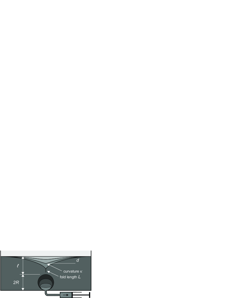
A highly deformable PDMS gel (Dow Corning CY52-276, components A & B mixed 1:1, shear modulus kPa) is prepared in a container of footprint 3x3 cm. A 10 times stiffer gel was prepared for some experiments by adding of Dow Corning Sylgard 184 (polymer & curing agent mixed 10:1, yielding kPa). The gels were cured overnight at room temperature, protecting the air-exposed free surface from dust. By depositing a water drop inside the gel prior to curing, we create a liquid inclusion of initial radius at the bottom of the container. denotes the initial distance between inclusion and free surface (cf. Fig. 1); we used mm and . Subsequently, the water is extracted slowly ( s for the droplet volume) through a small hole at the bottom (cf. Fig. 1), creating a quasi-stationary axisymmetric strain field in the gel, and an increasingly sharp indentation of the free surface. A two-dimensional version of the experiment was realized by creating a cylindrical inclusion at the bottom of the container. In that case, the inclusion was templated by a cylinder of polyethylene glycol ( g/mol, melting point ) which was removed by melting after the gel was cured.
The free surface profile was measured as a shadowgraph through a long-distance microscope with a spatial resolution on the order of 10 microns. The deformation field and the length of the self-contacting surface fold were determined by tracking fluorescent particles embedded inside the gel (see supplemental material for details sup ). The amplitude of the deformation is measured by , the deflection of the free surface relative to its reference level. The sharpness of the deflection is quantified by its curvature in the image plane.
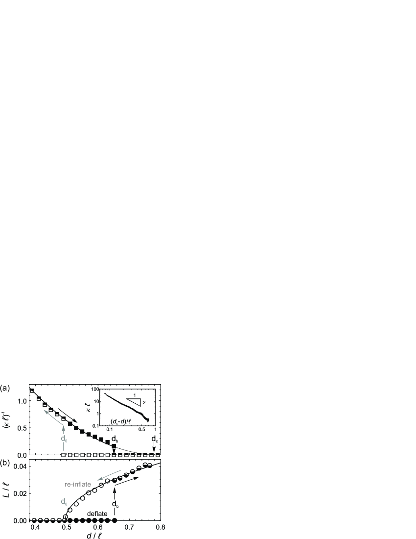
Figure 2 shows the result of a typical experimental run, obtained by first deflating the water drop to vanishing size (filled symbols), and subsequently re-inflating it up again to its original size (open symbols). The deformation is quantified by shown on the horizontal axis. Upon increasing deformation, the gel develops an increasingly sharp furrow, as measured by the dimensionless radius of curvature (panel (a); the furrow’s self-similar shape is investigated below). At a deformation , the furrow bifurcates toward a crease (similar to previously reported behavior Hohlfeld and Mahadevan (2011); Dervaux and Ben Amar (2012)): part of the surface folds into a self-contact of length , connected to a free-surface cusp of vanishing tip curvature. In the axisymmetric version of the experiment, this is accompanied by a breaking of axisymmetry, the crease being essentially two-dimensional. Experimental data are fitted with the scaling law (panel (a), solid line)
| (1) |
which suggests the existence of a critical deformation at which the tip radius of curvature vanishes; however, this critical scaling is cut off by a discontinuous (first order) transition toward the crease at .
Directly after formation of the crease, a self-contact of length forms, while the radius of curvature of the new structure jumps to zero. With increasing deformation, increases further (circles). Re-inflating the liquid inclusion again, so as to decrease , decreases beyond its original value to go to zero in a continuous fashion at another critical value ; this is described by the critical behavior (panel (b), solid line),
| (2) |
reminiscent of a second order transition, to be discussed below. Below , the crease disappears and the interface shape returns to a furrow, in the course of which the tip radius jumps to a finite value. Decreasing the deformation further, the tip radius returns to its original value along the same curve, indicating that the entire process is reversible. To check reversibility, we repeated the whole cycle several times for each specimen, which yielded nearly identical results (typical deviation ). Merely was slightly smaller by about as compared to the first creasing event. This could indicate the formation of a localized nucleation seed due to the initial creasing Chen et al. (2012).
The scaling laws Eqs. 1 and 2 are universal features of the creasing instability. These were consistently observed, where we in total considered about 25 different configurations (axisymmetric and 2D, soft and stiff gels) with mm and . precludes large deformations because of the limited droplet volume. For , creasing was not induced before the droplet was drained completely (axisymmetric samples; for 2D). Otherwise, all experiments show similar curves as in Fig. 2 with universal scaling laws. As expected, the precise values of and are not universal (see supplement sup ).
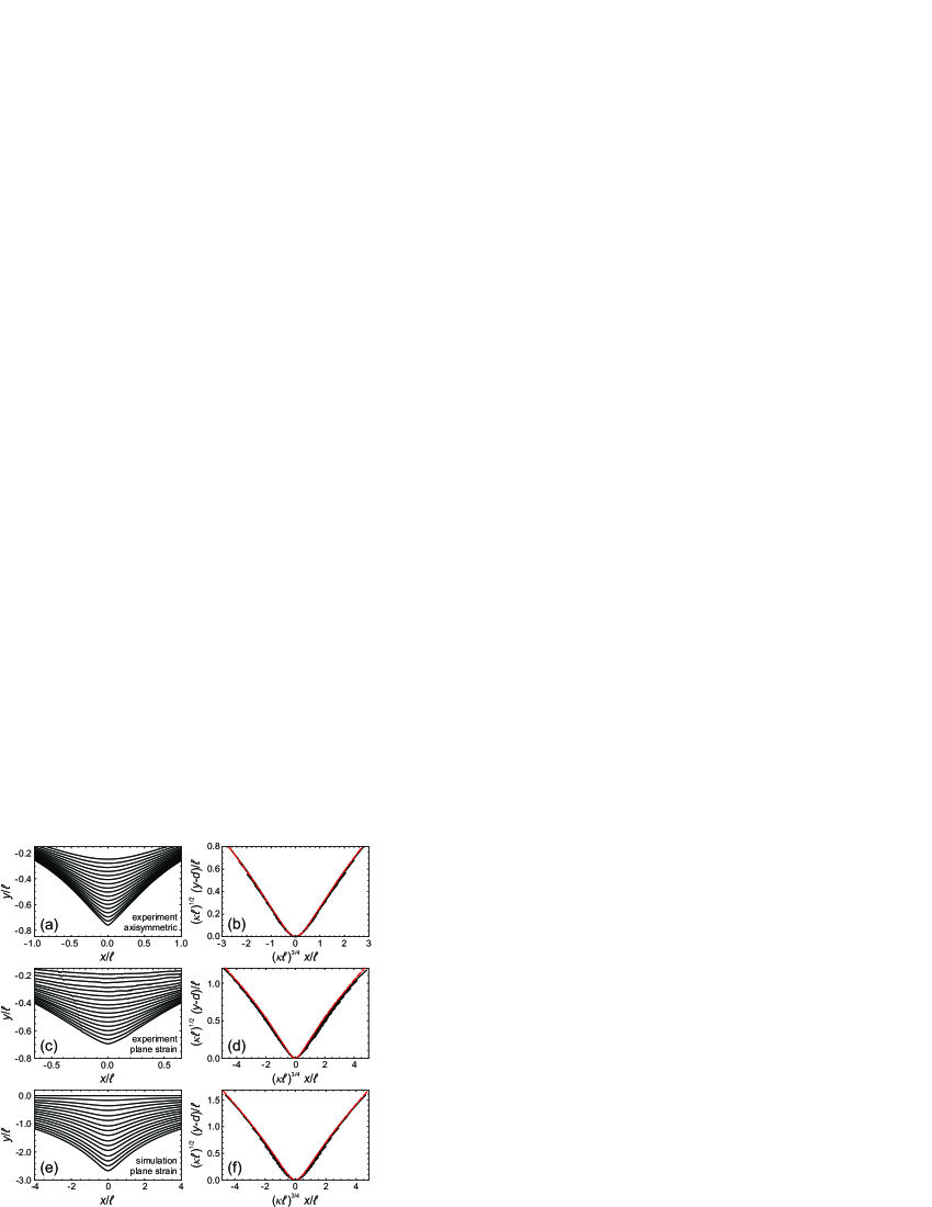
The shape of the furrow is perfectly self-similar, as is shown in Fig. 3. To describe this self-similar structure analytically, we hypothesize that the surface shape is described by a plane curve with a smooth parametric representation , which has been used successfully to describe cusp formation quantitatively in free surface flows and in optics Eggers and Fontelos (2015); Eggers and Suramlishvili (2017); a rigorous rationale for such a description is provided for example by a complex mapping between the free surface and the unit circle Jeong and Moffatt (1992), as has been verified experimentally for viscous flows Lorenceau (2003). To picture cusp formation of a parameterized curve geometrically, one can imagine these components being deformed smoothly such that the curve self-intersects. At the point of self-intersection, the curve is a cusp with a singular tip. Just before intersection the curve opens into a universal smooth curve.
Namely, a critical point of the curve corresponds to , so expanding about to lowest non-trivial order yields Eggers and Fontelos (2013)
| (3) |
where corresponds to the critical (cusp) point, and is a parameter controlling the opening of the cusp . In the -component we expanded to third order, since any quadratic term can be eliminated using , implying a rotation. The curvature of (3) at the origin is , so (3) can be written in similarity form
| (4) |
where is defined implicitly: , see Eggers and Fontelos (2013). As seen in Fig. 3 (b,d,f), the similarity form (4) is in excellent agreement with both 2D and 3D experiments and simulation, and the collapsed data agrees very well with the universal similarity function . The single adjustable parameter is determined by the outer geometry of the problem. In addition, the relation between the vertical deformation scale and implied by (4) is consistent with (1). Of course, this geometric analysis cannot describe the precise value of the tip curvature , which must be derived from large deformation elasticity theory Suo (2013a, b).
To show that the observations above are well described by the mechanics of elasticity, we performed two-dimensional (plane strain) finite element simulations implemented in oomph-lib Heil and Hazel (2006), using the theory of finite deformations Suo (2013a), with an incompressible neo-Hookean constitutive equation Suo (2013b). In large deformation theory the coordinates of the undeformed state of the system (the reference state, see Fig. 4) is mapped upon the current, deformed state of the system as . For a neo-Hookean elastic material, the Cauchy stress is Suo (2013a)
| (5) |
where is the shear modulus and the solid pressure (here defined up to a constant), which ensures incompressibility: . Elastic equilibrium is determined by . For simulation details see supplement sup . The result of the simulations is given in panels (e,f) of Fig. 3. They recover the same features as in experiments, including the similarity collapse with the same universal shape superimposed.
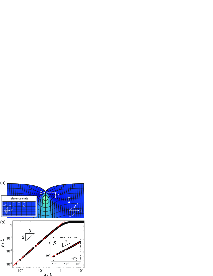
The remaining challenge is to understand the morphology of the creased state, which contains two singular points, respectively indicated as C and T in Fig. 4 (a). To derive a solution of the creased state, we start from the fold solution around point T Singh and Pipkin (1965); Hong et al. (2009), which maps an elastic half space onto a fold of infinite length (coordinates are defined in Fig. 4 (a); here the origin lies in point T):
| (6) |
which is an exact solution of (5). On the fold (), the principal stretches are , and the elastic free energy density is . The logarithmic divergence of near T is uncritical for a macroscopic description of the experiment since kPa down to molecular length scales. To numerically simulate the creased state, we use a large domain () under horizontal compression, impose (6) near T, and require a non-negative normal traction and vanishing tangential traction on TC (see supplement for details sup ).
Figure 4 (a) shows the deformed computational domain, while (b) reveals a power-law behavior of the interface above the self-contact, with 4 decades of spatial resolution. Hence, the interface forms an ideal cusp, , which is the limiting case in (3). In the supplement sup we also provide experimental evidence for this scaling. To access the surface profile near the self-contact experimentally with sufficient spatial resolution, we bent an elastic rod until it creased on its surface and recorded its shadow graph. Despite the significantly different outer geometry, we find the same 2/3 exponent for the morphology of the crease, highlighting the universality of this result.
This scaling can be derived analytically by noting that near C, where the fold opens, the shape is slender: (from now on we use C as the coordinate origin). Hence deformations relative to that of the fold are small and we can expand to linear order in the deformations :
| (7) |
where is the stretch near C. We use coordinate systems as shown in Fig. 4 (a), but for simplicity use a reference state which is rotated clockwise by 90 degrees. As shown in Biot (1963), if we introduce a stream function , , the linearized elasticity problem reduces to
| (8) |
where and denote the Laplacian in the deformed and reference coordinates, respectively.
Similar to the analysis of the cusp in a viscous fluid Eggers and Fontelos (2015), we make the self-similar ansatz ; corresponds to the cusp line, along which we impose vanishing shear and, outside the self-contact, vanishing normal stress. Using that is odd, we find from the second equation (8) that Eggers and Fontelos (2015)
| (9) |
and , where is an arbitrary constant. Now solving (9) in reference coordinates, homogeneous solutions are . In polar coordinates, the transformation between deformed and reference coordinates reads and , and so
| (10) |
An odd particular solution of (9) is found from the standard formula as , where
| (11) |
A general solution to (8) can be written , where the constants must be chosen to satisfy at , where is the true normal.
For there to be a non-trivial solution, the determinant of this system of equations must vanish, which after using that , yields the condition . Thus the determinant vanishes for , where , irrespective of the stretch near C. Among these possible solutions, the dominant value of for which the pressure is not singular at the cusp tip is , which means that the cusp opens with the universal exponent , as is confirmed over four decades in Fig. 4 (b). Accordingly, implies that the normal traction near the edge of the contact scales like , as confirmed numerically (inset). Thus, both deformation and traction scale in the same way as a Hertz contact Johnson (1985). We also note that the above calculation provides a rationale for the scaling in the far field of the furrow: away from its rounded tip, the furrow’s geometry is again slender and can described by the same analysis.
Finally, we analyze the length of the fold. Since the energy density of the fold solution (6) is constant, the contribution from the fold is , since sets the size of the area over which deformation is significant. We can assume that the energy of the rest of the strain field is a smooth function of the deformation . Hence, if the creation of the fold takes place in a reversible fashion, we have . Expanding linearly about , where , we obtain (2). Apart from the experiment of Fig. 2, this scaling law is confirmed with great precision by the numerical simulation of a neo-Hookean material shown in Fig. 4 sup .
In conclusion, our liquid-inclusion experiments allowed us to investigate quantitatively localized furrows and creases which form on the surface of an elastic medium under compression, and to document the hysteretic transitions between them. We are able to describe the self-similar shapes of these furrows quantitatively, in agreement with both experiment and neo-Hookean non-linear elasticity. Based on elasticity theory, we are able to explain the scaling of the width of both furrow and crease. These scaling laws reveal that the elastic singularity is a “true” geometric cusp, and belongs to the same universality class as caustics in optics and free surface flows.
Acknowledgements.
Acknowledgments.—
We are grateful to J. Dervaux and L. van Wijngaarden for discussions. SK, AP and JHS acknowledge financial support from ERC (the European Research Council) Consolidator Grant No. 616918. J.E.’s work was supported by Leverhulme Trust Research Project Grant RPG-2012-568.
References
- Tanaka (1986) T. Tanaka, Physica A 140, 261 (1986).
- V. Trujillo and Hayward (2008) J. K. V. Trujillo and R. C. Hayward, Soft Matter 4, 564 (2008).
- Hohlfeld and Mahadevan (2011) E. Hohlfeld and L. Mahadevan, Phys. Rev. Lett. 106, 105702 (2011).
- Dervaux et al. (2011) J. Dervaux, Y. Couder, M. A. Guedeau-Boudeville, and M. Ben Amar, Phys. Rev. Lett. 107, 018103 (2011).
- Hohlfeld and Mahadevan (2012) E. Hohlfeld and L. Mahadevan, Phys. Rev. Lett. 109, 025701 (2012).
- Holmes and Crosby (2010) D. P. Holmes and A. J. Crosby, Phys. Rev. Lett. 105, 038303 (2010).
- Paulsen et al. (2016) J. D. Paulsen, E. Hohlfeld, H. King, J. Huang, Z. Qiu, T. P. Russell, N. Menon, D. Vella, and B. Davidovitch, Proceedings of the National Academy of Sciences 113, 1144 (2016).
- Hong et al. (2009) W. Hong, X. Zhao, and Z. Suo, Appl. Phys. Lett. 95, 111901 (2009).
- Ben Amar and Ciarletta (2010) M. Ben Amar and P. Ciarletta, J. Mech. Phys. Solids 58, 935 (2010).
- Diamant and Witten (2011) H. Diamant and T. A. Witten, Phys. Rev. Lett. 107, 164302 (2011).
- Cai et al. (2012) S. Cai, D. Chen, Z. Suo, and R. C. Hayward, Soft Matter 8, 1301 (2012).
- Cao and Hutchinson (2012) Y. Cao and J. W. Hutchinson, Proc. Roy. Soc. A 468, 94 (2012).
- Ghatak and Das (2007) A. Ghatak and A. L. Das, Phys. Rev. Lett. 99, 076101 (2007).
- Dervaux and Ben Amar (2012) J. Dervaux and M. Ben Amar, Annu. Rev. Cond. Matt. 3, 311 (2012).
- Chen et al. (2012) D. Chen, S. Cai, Z. Suo, and R. C. Hayward, Phys. Rev. Lett. 109, 038001 (2012).
- Wang and Cai (2014) H. Wang and S. Cai, Soft Matter 11, 1058 (2014).
- Jin et al. (2014) L. Jin, D. Chen, D. Chen, Z. Suo, and R. C. Hayward, Soft Matter 10, 303 (2014).
- Stewart et al. (2016) P. S. Stewart, S. L. Waters, T. E. Sayed, D. Vella, and A. Goriely, Extreme Mechanics Letters 8, 22 (2016).
- Biot (1963) M. A. Biot, Appl. Sci. Res. 12, 168 (1963).
- (20) Supplementary material available at http://...
- Eggers and Fontelos (2015) J. Eggers and M. A. Fontelos, Singularities: Formation, Structure, and Propagation (Cambridge University Press, Cambridge, 2015).
- Eggers and Suramlishvili (2017) J. Eggers and N. Suramlishvili, Eur. J. Mech. B 65, 107 (2017).
- Jeong and Moffatt (1992) J.-T. Jeong and H. K. Moffatt, J. Fluid Mech. 241, 1 (1992).
- Lorenceau (2003) E. Lorenceau, Phd thesis, Université Pierre et Marie Curie - Paris VI (2003), URL https://tel.archives-ouvertes.fr/tel-00003275.
- Eggers and Fontelos (2013) J. Eggers and M. A. Fontelos, Panoramas et Synthèses 38, 69 (2013).
- Suo (2013a) Z. Suo, Finite deformation: general theory (2013a), URL http://imechanica.org/node/538.
- Suo (2013b) Z. Suo, Elasticity of rubber-like materials (2013b), URL http://imechanica.org/node/14146.
- Heil and Hazel (2006) M. Heil and A. Hazel, in Fluid-Structure Interaction, edited by M. Schäfer and H.-J. Bungartz (Springer, 2006), pp. 19–49.
- Singh and Pipkin (1965) M. Singh and A. C. Pipkin, ZAMP 16, 706 (1965).
- Johnson (1985) K. L. Johnson, Contact mechanics (Cambridge University Press, 1985).