A fiber coupled cavity QED source of identical single photons
Abstract
A high-fidelity source of identical single photons is essential for numerous quantum technologies such as quantum repeaters and optical quantum information processing Santori2002 ; Yamamoto1999 . Hallmarks thereof are a near-unity single-photon purity, near-unity indistinguishability of consecutively emitted photons, and high brightness through a near-unity number of photons per time bin Somaschi2015a ; Ding ; Aharonovich2016 . In order to embed such sources in quantum networks, optical fiber integration is essential but complicated by cryogenic compatability and noise. Here we demonstrate a resonantly pumped, quantum dot (QD) based, transmission operated, single-mode fiber coupled single photon source with a purity of 97, indistinguishability of 90, and a brightness of 17. This is achieved by deploying a unique micropillar cavity design in a closed-cycle cryostat, which is operated using a through-fiber cross-polarization technique to remove the pump laser light from the resonantly scattered single photons. These results pave the way for fully fiber integrated photonic quantum networks, as our technology is equally applicable for cavity-QED based photonic quantum gates Kim2013 ; Reiserer2014a .
For a single photon source, high brightness and on-demand availability is crucial for efficient implementation of quantum photonic protocols. Additionally, to exploit the power of quantum interference such as in boson sampling, consecutively produced photons need to be indistinguishable, meaning that their wave functions must overlap well. Until recently, heralded spontaneous parametric down conversion sources Barz2010 were state of the art for single photon sources (SPS) Eisaman2011 , with which most quantum communication and optical quantum computing protocols have been demonstrated Takemoto2015 . The main problem of these sources is that the Poissonian statistics of the generated twin photons will always result in a trade-off between single-photon purity (the absence of N>1 photon number states) and brightness (the probability to obtain a photon per time slot).
One way to deterministically produce single photons is to use trapped atoms Kuhn2002 , where single photon rates up to 200 kHz have been obtained recently Higginbottom2016 . In order to enable integration and increasing the photon rate, solid-state systems have been investigated. An excellent candidate is a semiconductor QD Santori2002 ; Bennett2016a ; Hennessy2007 . QDs have nanosecond lifetime transitions that enable GHz rate production of single photons as required for numerous quantum technologies. Compared to other solid state emitters such as NV centers, nanowire QDs, excitons in carbon nanotubes or two-dimensional materials Rogers2014 ; Sipahigil2014 , self-assembled QDs in cavities can show almost perfect purity and indistinguishability Somaschi2015a . A challenging task is to couple the quantum emitter to propagating light fields with near-unity efficiency. This can be achieved by placing them in optical micro cavities, which additionally increases the emission rate by cavity-QED Purcell enhancement, such as micropillar cavities Snijders2016 ; Santori2002 , photonic crystal cavities Muller2014 , or ring resonators Davanco2016 .
For the next major step in implementing single photon sources in complex photonic quantum networks, such as for quantum boson sampling or cluster state quantum computation, coupling to a single mode optical fiber is essential. Several challenges are connected to this: cryogenic compatibility Haupt2010 , resonant optical pumping (a preprint about a nonresonantly pumped device appeared recently Schlehahn2017 ), high coupling efficiency and robust and stable polarization control. Another approach is to employ fiber-tip micro cavities but the photon collection efficiency is limited to about 10% to date Muller2009 ; Greuter2015a .
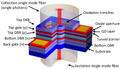
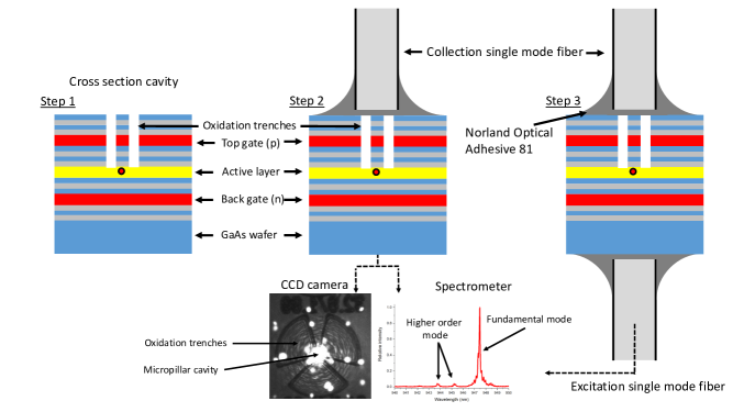
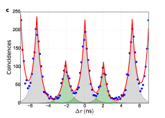
Here, we show a prototype of a fully fiber coupled solid-state resonantly pumped and transmission-based source of identical photons. Our fiber coupled single photon device is sketched in Fig. 1: The device consists of a layer of self-assembled InAs/GaAs QDs embedded in a micropillar Fabry–Perot cavity (Purcell factor ) grown by molecular beam epitaxy Strauf2007a . The QD layer is embedded in a P–I–N junction, separated by a 27 nm thick tunnel barrier from the electron reservoir to enable tuning of the QD resonance frequency by the quantum-confined Stark effect. Since we do not use air-guided micropillars but an oxide aperture for 3D confinement Bonato2012 , the device is very robust and the optical properties do not degrade by attachment of the fibers. The singlemode fibers are carefully aligned and connected by an UV-light curable adhesive to the front and back of the device (Supplementary Section 1), allowing for transmission measurements with full control of the optical polarization.
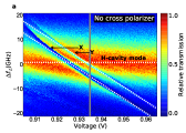
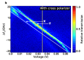
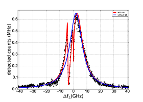
The fundamental cavity mode is split in two linearly polarized modes, the H and V mode, induced by a small ellipticity of the cavity cross-section. Similarly, the neutral exciton transition of the QD is split in two linearly polarized transitions by the fine structure exchange interaction. Fig. 2a shows a false color plot of the transmission through the sample as a function of the applied voltage and laser frequency. Using a free-space polarizer and a fiber polarization controller, the input polarization is set along the H cavity polarization axes. The transmitted light is sent to a single photon detector. The two fine structure split QD transitions are clearly visible as dips in the transmission spectrum that shift as a function of the applied electric field. A cross sectional plot of Fig. 2a (grey line) is shown in Fig. 2c (red line). The depth of the dips indicate the “X” QD transition couples better to the H cavity mode than the “Y” QD transition. This is confirmed by comparison to a numerical model taking all relevant cavity-QED and polarization effects into account (Supplementary Section 3). From this model we also determine the angle between the X QD axis and the H cavity mode axis to be ∘, and the polarization splitting of the fundamental cavity mode (18 GHz).
Fig. 2b and c (blue line) show single photons that are filtered from the transmitted light with a combination of a fiber polarization controller and a free-space optical polarizer set to extinguish the transmitted laser light (cross polarization). We excite the system along the H cavity mode polarization but detect only photons emitted from the V-polarized cavity mode. This is ideal for efficient collection of the single photons that are coherently scattered from the Y-transition of the QD, as is seen in Fig. 2b. This is a workable scheme because for excitation of the QD-cavity system, we can simply remedy the reduced coupling of the Y QD transition to the H-polarized cavity mode by increasing the laser power, while the emitted single photons are very efficiently collected by the V-polarized cavity mode. This also means that the Y QD transition acts here as the better single photon source than the X QD transition.
We now investigate the dependency between maximum single photon rate and single photon purity that is achievable with the present device. For this, we first perform continuous-wave resonant spectroscopy experiments with a single frequency diode laser.
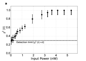
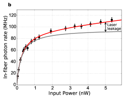
We measure the second order correlation and the flux of emitted photons as a function of the incident laser power (Fig. 3a & b). This measurement is carried out under the above-mentioned cross-polarization condition with an extinction ratio of about . Fig. 3a shows the second order correlation function at as a function of the incident laser power, while Fig. 3b shows the emitted single photon rate measured simultaneously. For increasing laser power, we observe a saturation of the single-photon count rate at around 1 nW, which corresponds well to previous results on related devices Bakker2015f . Based on the bare lifetime of the QD ( ns-1) one would expect that GHz rate single photons can be obtained, but we observe an increase of for increasing laser power. This is investigated in Fig. 3b (red line), where we have taken into account the saturation response of the resonantly driven two level system Lou , and the laser leakage due to a non-perfect optical polarization extinction. From this we can conclude that residual coherent excitation laser light is responsible for the increase in the second order correlation at higher laser powers.
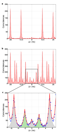
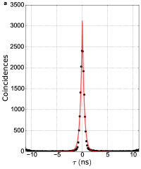
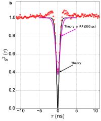
For quantum photonic applications, single photons are required on demand with precise timing. We realize this using a resonant (around 932.58 nm) pulsed laser with 20 ps pulse length and 12.5 ns period. These values are well-matched to the quantum dot transition in the cavity as shown in Fig. 2c. Using a pulsed laser, we are no longer limited by the jitter of the single photon detectors and can obtain a more accurate value for . At a sufficient low power of 100 pW, we measure a second order correlation of as shown in Fig. 4a. Note that we did not use spectral filtering of the cavity emitted light, in contrast to previous investigations Somaschi2015a . As we have investigated above, is in our case limited by imperfect extinction of the excitation laser light.
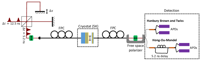
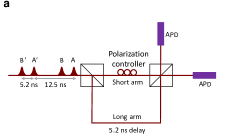
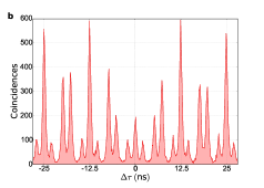
Next we determine the indistinguishability of two successively produced single photons. For this, we send the emitted (single) photons into a fiber-based Mach-Zehnder interferometer where one arm introduces a delay of 5.2 ns. In order to create two excitation-laser pulses with the exact same delay of 5.2 ns, we use a Michelson-type setup with adjustable delay. As a result, consecutively emitted photons arrive simultaneously at the final fiber splitter. We again measure photon correlations between both output ports (Supplementary Section 2). If two consecutively produced single photons are indistinguishable, they will undergo perfect quantum interference and “bunch”, i.e. two-photon coincidences at are expected to be absent in the ideal case. This can be seen in Fig. 4b, in particular if compared to the case where the photons are made distinguishable artificially (Supplementary Section 5). By fitting the data with double exponential functions and taking into account a finite value of , we obtain an indistinguishability of (Fig. 4c). Most of the coincidences that are still present at are due to the fact that the is not completely zero. By comparing the 80 MHz repetition rate of the laser to the detected single photon rate, and by taking detection efficiency and loss carefully into account, we obtain a brightness of the photons in the detection fiber of photons per laser pulse.
In conclusion, we have shown a prototype of a fully fiber coupled solid-state single photon source that produces on-demand single photons with a purity of , indistinguishability of and a brightness of . These figures are already very promising for using such a device for quantum boson sampling or for quantum-light spectroscopy applications Dorfman2016 . Furthermore, we have demonstrated a first all-fiber coupled cavity-QED based photonic quantum gate that filters out single photons from pulses of coherent laser light with a scheme that is also compatible with more complex excitation schemes Dada2016 . A next step is charging of the QD with a single electron or hole spin to create a quantum memory Kroutvar2004 which makes the device usable as a quantum node for remote entanglement generation, quantum key distribution, and distributed quantum computation.
Supplemental Information
I Fiber coupled cavity QED device
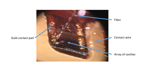
Fig. S1 shows a microscope image of the fiber coupled cavity-QED device, visible is the front fiber attached to the sample and the bond wires connected to the gold bond pads.
Attaching the fibers to the device requires three steps (see Fig. S2).
Step 1: The sample is mounted in an optical spectroscopy setup containing a long working distance microscope. The setup allows for precisely aligning the single mode fibers with a motorized translation stage.
Step 2: Collection fiber attachment. Broadband light (900-980 nm) from a single mode fiber coupled superluminiscent diode is sent into the collection fiber output. The other, cleaved, fiber end is roughly positioned to the cavity by observing nonresonant transmitted light using the microscope. For mode matching the fiber to the cavity mode, the transmitted light is sent to a 1 m spectrometer. The optimal position is found by maximizing the transmission in the fundamental mode of the cavity and reducing the higher order TE/TM modes. After finding the optimal position, the single mode fiber is vertically moved up so that a drop of Norland Optical Adhesive 81 can be put onto the cleaved fiber facet. After bringing the fiber back to its original position, the adhesive should touch the sample which is verified with an optical microscope. After again optimizing the position, the adhesive is cured using UV-light. Before removing the device from the setup, the fiber is firmly attached to the copper mount using Stycast.
Step 3: Excitation fiber attachment. We flip the device around and send again broadband light into the collection fiber. Rough alignment of the excitation fiber at the bottom of the device is done by aligning the fiber to the fundamental cavity mode using the microscope, after which we use again a spectrometer to fine tune the position. Then, the procedure from step 2 is used for attaching the fiber.
The cavity mode of our device has at the front surface a waist of µm and at the back a waist of µm at around 955 nm Bonato2012 . The increased waist at the back of the sample is due to the µm thick GaAs wafer. The fibers (Thorlabs 780HP) have a core radius of µm and 0.13 NA, which results in a mode waist of µm. Neglecting the phase and only taking into account the mode waist of the fiber, we have at the front side of the cavity a coupling efficiency of GhatakK.Thyagarajan1998
Here, is the transverse misalignment distance. Setting we obtain an optimal efficiency of . Experimentally, we obtain for our device a coupling efficiency of . The reason for this deviation is most likely a slight misalignment of the fiber, which happens during curing of the adhesive and cooling down of the sample; this could be avoided by improved management of thermal expansion. The fiber at the back of the sample has a reduced incoupling efficiency of 0.6, due to the presence of the thick GaAs wafer. For operation of our single photon source this reduced coupling efficiency is irrelevant because we excite the system from the back where the coupling efficiency only effects the required excitation laser power.
II Optical setup
The optical setup used to measure photon correlations to obtain single photon purity and indistinguishability is shown in Fig. S3. A pulse delay setup can be used to create from a mode-locked 80 MHz Ti:Sa laser double pulses, which are sent to the micropillar cavity. The transmitted photons are analyzed with a Hanbury Brown Twiss setup to determine the second order correlation function , or with a highly unbalanced Mach-Zehnder interferometer to observe Hong-Ou-Mandel type photon bunching of consecutively emitted photons to determine their indistinguishability . Almost all components in the setup are fiber-based or fiber-coupled, except the production of the double laser pulses and the polarizers (fiber U-benches). The delay between the double pulses is precisely adjusted to the Mach-Zehnder interferometer delay by scanning while observing first-order interference in absence of the cavity-QED device. This interference signal becomes maximal when the position of matches the in-fiber delay of about 5.2 ns.
III System Parameters
In order to theoretically model the quantum dot cavity-QED system we use an extended version of a model for a two level system in an optical cavity driven by a classical coherent laser field. Using Qutip Johansson2012a ; Johansson2013 we solve numerically the quantum master equation in the rotating wave approximation. Details about the model we use to fit the data can be found in Ref. Snijders2016 .
We iteratively fit the simulation results to experimental data (shown in Fig. S4). We obtain a cavity splitting of GHz and a cavity decay rate ns-1. Now we keep these parameters fixed and optimize the model for the case when only the H-polarized cavity mode is excited to obtain the remaining 4 parameters of our QD-cavity system (S4). We find a QD-cavity coupling constant ns-1, a population relaxation rate of ns-1, a pure dephasing rate of ns-1, a QD fine structure splitting of GHz, and for the angle between the H-polarized cavity mode and the X QD transition . The frequencies of the two fine-structure-split QD transitions in Fig. S4 are GHz and GHz, and the frequencies of the polarization split fundamental cavity modes are GHz and GHz.
From these parameters we find a cooperativity of which corresponds to a Purcell enhancement of the excited state decay rate of assuming that the QD transition is on resonance with the cavity transition.
IV Detector response
The two-detector response for our single photon counting detectors (SPCM-AQR-14) is given by a double exponential function (Fig. S5a). Convoluting the theoretical prediction with this detector response enables us to predict for a continuous wave laser. As is shown in Fig S5b, this agrees well with the experimental data (red dots S5b). This proves that measured with a continuous wave laser is limited by detector jitter.
V Indistinguishability measurement analysis
Here we explain the procedure to analyze the indistinguishability measurements. First, we examine the ideal case without losses and with ideal single-photon pulses (unity single-photon purity). We assume an excitation laser pulse spacing of 5.2 ns. We need to consider two double pulses and we label the photons as shown in Fig. S6a: photon A at 0 ns, B at 5.2 ns, A’ at 12.5 ns, and photon B’ at 17.2 ns.
The detection is done using an unbalanced Mach Zehnder interferometer, where one arm introduces a delay equal to the pulse delay (5.2 ns). Photon correlations behind the last fiber splitter are measured. We list all possible combinations of photons for which a two-photon detection event can happen with a particular temporal delay between the photons. In table S1 below, the first row indicates the delay between all possible photon combinations before the Mach-Zehnder interferometer. The lower 4 rows show the four possible pathways which pairs of photons can take, the number gives their relative delay at the single photon detectors. The number of occurrences of a particular delay time is directly proportional to the detection probability. For example, it is 2 times more likely to detect two photons with 5.2 ns than it is with 2.1 ns, which agrees very well with the experimental data in Fig. 4c (main text).
| AA’ (ns) | BB’ (ns) | BA’ (ns) | AB (ns) | |
|---|---|---|---|---|
| Laser pulse delay (before detection in MZ) | 12.5 | 12.5 | 7.3 | 5.2 |
| first photon long arm | 7.3 | 7.3 | 2.1 | 0 |
| both photons short arm | 12.5 | 12.5 | 7.3 | 5.2 |
| both photons long arm | 12.5 | 12.5 | 7.3 | 5.2 |
| first photon short arm | 17.2 | 17.2 | 12.5 | 10.4 |
Indistinguishability: If the two photons are indistinguishable and arrive simultaneously at the last fiber splitter, Hong-Ou-Mandel quantum interference leads to photon bunching and prevents detection of coincidence events, therefore, the “AB” event with in table S1 disappears.
To contrast the indistinguishability measurement shown in Fig. 4c in the main text to the case where the photons are perfectly distinguishable, we perform an experiment where the photons are made artificially different by giving them orthogonal polarization. The result in Fig. S6b clearly shows the absence of Hong-Ou-Mandel type photon bunching by the strong correlations at . Fig. S6c shows a zoom-in with double-exponential fits to the measured data. This agrees excellently to the expectation in table S1, note that the probability should be multiplied with 2 due to the coincidence of .
This model can be improved by taking into account the losses of the fiber splitters (we assume that both fiber splitters are identical) and a finite purity of the single photon pulses. To do this, we follow the procedure of Ref. Santori2002 : The probability for a detection event at the center peak normalized by the repetition rate and detection efficiency is given by
where is the mean wave function overlap or indistinguishability, is the visibility of the Mach-Zehnder interferometer and and are the reflection and transmission coefficients of the fiber splitters. Comparing this to the probability for a detection event at ns, we obtain
For our fiber splitters we find , , . We determine the coincidence probability ratio obtained from double exponential fits in Fig. 4c (main text) is Combined with the single-photon purity measurement with (main text, Fig. 4a), we obtain for the indistinguishability
Acknowledgements.
We thank D. Kok and M.F. Stolpe for fruitful discussions. We acknowledge funding from FOM-NWO (08QIP6-2), from NWO/OCW as part of the Frontiers of Nanoscience program, and from the National Science Foundation (NSF) (0901886, 0960331).Author contributions
JAF, JN, AG, JEB, DB, and WL designed and fabricated the devices; HS, VP, MPE, DB, and WL conceived and conducted the optical experiments. All authors contributed to the manuscript.
References
- (1) Santori, C., Fattal, D., Vučković, J., Solomon, G. S. & Yamamoto, Y. Indistinguishable photons from a single-photon device. Nature 419, 594 (2002).
- (2) Yamamoto, Y., Kim, J., Benson, O. & Kan, H. A single-photon turnstile device. Nature 397, 500 (1999).
- (3) Somaschi, N., Giesz, V., De Santis, L., Loredo, J. C., Almeida, M. P., Hornecker, G., Portalupi, S. L., Grange, T., Antón, C., Demory, J., Gómez, C., Sagnes, I., Lanzillotti-Kimura, N. D., Lemaítre, A., Auffeves, A., White, A. G., Lanco, L. & Senellart, P. Near-optimal single-photon sources in the solid state. Nat. Photonics 10, 340 (2016).
- (4) Ding, X., He, Y., Duan, Z.-C., Gregersen, N., Chen, M.-C., Unsleber, S., Maier, S., Schneider, C., Kamp, M., Höfling, S., Lu, C.-Y. & Pan, J.-W. On-Demand Single Photons with High Extraction Efficiency and Near-Unity Indistinguishability from a Resonantly Driven Quantum Dot in a Micropillar. Phys. Rev. Lett. 116, 020401 (2016).
- (5) Aharonovich, I., Englund, D. & Toth, M. Solid-state single-photon emitters. Nat. Photonics 10, 631 (2016).
- (6) Kim, H., Bose, R., Shen, T. C., Solomon, G. S. & Waks, E. A quantum logic gate between a solid-state quantum bit and a photon. Nat. Photonics 7, 373 (2013).
- (7) Reiserer, A., Kalb, N., Rempe, G. & Ritter, S. A quantum gate between a flying optical photon and a single trapped atom. Nature 508, 237 (2014).
- (8) Barz, S., Cronenberg, G., Zeilinger, A. & Walther, P. Heralded generation of entangled photon pairs. Nat. Photonics 4, 553 (2010).
- (9) Eisaman, M. D., Fan, J., Migdall, A., Polyakov, S. V. & Fan, J. Invited Review Article: Single-photon sources and detectors. Rev. Sci. INSTRUMENTS 82, 071101 (2011).
- (10) Takemoto, K., Nambu, Y., Miyazawa, T., Sakuma, Y., Yamamoto, T., Yorozu, S. & Arakawa, Y. Quantum key distribution over 120 km using ultrahigh purity single-photon source and superconducting single-photon detectors. Sci. Rep. 5, 14383 (2015).
- (11) Kuhn, A., Hennrich, M. & Rempe, G. Deterministic Single-Photon Source for Distributed Quantum Networking. Phys. Rev. Lett. 89, 067901 (2002).
- (12) Higginbottom, D. B., Slodička, L., Araneda, G., Lachman, L., Filip, R., Hennrich, M. & Blatt, R. Pure single photons from a trapped atom source. New J. Phys. 18, 093038 (2016).
- (13) Bennett, A. J., Lee, J. P., Ellis, D. J. P., Farrer, I., Ritchie, D. A. & Shields, A. J. A semiconductor photon-sorter. Nat. Nanotechnol. 11, 857 (2016).
- (14) Hennessy, K., Badolato, A., Winger, M., Gerace, D., Atatüre, M., Gulde, S., Fält, S., Hu, E. L. & Imamoğlu, A. Quantum nature of a strongly coupled single quantum dot–cavity system. Nature 445, 896 (2007).
- (15) Rogers, L. J., Jahnke, K. D., Teraji, T., Marseglia, L., Müller, C., Naydenov, B., Schauffert, H., Kranz, C., Isoya, J., McGuinness, L. P. & Jelezko, F. Multiple intrinsically identical single-photon emitters in the solid state. Nat. Commun. 5, 4739 (2014).
- (16) Sipahigil, A., Jahnke, K., Rogers, L., Teraji, T., Isoya, J., Zibrov, A., Jelezko, F. & Lukin, M. Indistinguishable Photons from Separated Silicon-Vacancy Centers in Diamond. Phys. Rev. Lett. 113, 113602 (2014).
- (17) Snijders, H., Frey, J. A., Norman, J., Bakker, M. P., Langman, E. C., Gossard, A., Bowers, J. E., van Exter, M. P., Bouwmeester, D. & Löffler, W. Purification of a single-photon nonlinearity. Nat. Commun. 7, 12578 (2016).
- (18) Müller, K., Rundquist, A., Fischer, K. A., Sarmiento, T., Lagoudakis, K. G., Kelaita, Y. A., Sánchez Muñoz, C., Del Valle, E., Laussy, F. P. & Vučković, J. Coherent generation of nonclassical light on chip via detuned photon blockade. Phys. Rev. Lett. 114, 1 (2014). eprint 1408.5942.
- (19) Davanço, M., Liu, J., Sapienza, L., Zhang, C.-Z., De, J. V., Cardoso, M., Verma, V., Mirin, R., Nam, S. W., Liu, L. & Srinivasan, K. A heterogeneous III-V/silicon integration platform for on-chip quantum photonic circuits with single quantum dot devices 1–23 (2016). eprint arXiv: 1611.07654.
- (20) Haupt, F., Oemrawsingh, S. S. R., Thon, S. M., Kim, H., Kleckner, D., Ding, D., Suntrup III, D. J., Petroff, P. M. & Bouwmeester, D. Fiber-connectorized micropillar cavities. Appl. Phys. Lett 97, 131113 (2010).
- (21) Schlehahn, A., Fischbach, S., Schmidt, R., Kaganskiy, A., Strittmatter, A., Rodt, S., Heindel, T. & Reitzenstein, S. A stand-alone fiber-coupled single-photon source (2017). eprint arXiv: 1703.10536.
- (22) Muller, A., Flagg, E. B., Metcalfe, M., Lawall, J. & Solomon, G. S. Coupling an epitaxial quantum dot to a fiber-based external-mirror microcavity. Appl. Phys. Lett. 95, 173101 (2009).
- (23) Greuter, L., Starosielec, S., Kuhlmann, A. V. & Warburton, R. J. Towards high-cooperativity strong coupling of a quantum dot in a tunable microcavity. Phys. Rev. B 92, 045302 (2015).
- (24) Strauf, S., Stoltz, N. G., Rakher, M. T., Coldren, L. A., Petroff, P. M. & Bouwmeester, D. High-frequency single-photon source with polarization control. Nat. Photonics 1, 704 (2007).
- (25) Bonato, C., Gudat, J., de Vries, K., Thon, S. M., Kim, H., Petroff, P. M., van Exter, M. P. & Bouwmeester, D. Optical modes in oxide-apertured micropillar cavities. Opt. Lett. 37, 4678 (2012).
- (26) Bakker, M. P., Snijders, H., Löffler, W., Barve, A. V., Coldren, L. A., Bouwmeester, D. & van Exter, M. P. Homodyne detection of coherence and phase shift of a quantum dot in a cavity. Opt. Lett. 40, 3173 (2015).
- (27) Loudon, R. The Quantum Theory of Light (Oxford Science publications) (Oxford University Press, USA, 1973), 3rd ed edn.
- (28) Dorfman, K. E., Schlawin, F. & Mukamel, S. Nonlinear optical signals and spectroscopy with quantum light. Rev. Mod. Phys. 88, 045008 (2016).
- (29) Dada, A. C., Santana, T. S., Malein, R. N. E., Koutroumanis, A., Ma, Y., Zajac, J. M., Lim, J. Y., Song, J. D. & Gerardot, B. D. Indistinguishable single photons with flexible electronic triggering. Optica 3, 493 (2016).
- (30) Kroutvar, M., Ducommun, Y., Heiss, D., Bichler, M., Schuh, D., Abstreiter, G. & Finley, J. J. Optically programmable electron spin memory using semiconductor quantum dots. Nature 432, 81 (2004).
- (31) Ghatak, K. & Thyagarajan, A. An introduction to fiber optics (Cambridge University Press, 1998).
- (32) Johansson, J., Nation, P. & Nori, F. QuTiP: An open-source Python framework for the dynamics of open quantum systems. Comput. Phys. Commun. 183, 1760 (2012).
- (33) Johansson, J. R., Nation, P. D. & Nori, F. QuTiP 2: A Python framework for the dynamics of open quantum systems. Comput. Phys. Commun. 184, 1234 (2013).