Electrical switching of magnetic polarity in a multiferroic BiFeO3 device at room temperature
Abstract
We have directly imaged reversible electrical switching of the cycloidal rotation direction (magnetic polarity) in a -BiFeO3 epitaxial-film device at room temperature by non-resonant x-ray magnetic scattering. Consistent with previous reports, fully relaxed -BiFeO3 epitaxial films consisting of a single ferroelectric domain were found to comprise a sub-micron-scale mosaic of magneto-elastic domains, all sharing a common direction of the magnetic polarity, which was found to switch reversibly upon reversal of the ferroelectric polarization without any measurable change of the magneto-elastic domain population. A real-space polarimetry map of our device clearly distinguished between regions of the sample electrically addressed into the two magnetic states with a resolution of a few tens of micron. Contrary to the general belief that the magneto-electric coupling in BiFeO3 is weak, we find that electrical switching has a dramatic effect on the magnetic structure, with the magnetic moments rotating on average by 90∘ at every cycle.
pacs:
77.55.Nv, 75.85.+t, 61.05.cpI Introduction
Multiferroicity as a phenomenon is defined by the presence of an antiferromagnetic order parameter that is quadratic in the magnetic moments and is coupled linearly to the ferroelectric (FE) polarization. Different multiferroic mechanisms differ in the nature of the magnetic order parameter: for the most common cycloidal multiferroics Mostovoy (2006), this parameter is represented by a magnetic polarity, and is commonly referred to as “cycloidal rotation direction” or “magnetic chirality”. For the other two known varieties — ferroaxial Johnson et al. (2011) (including p-d hybridised Arima (2007)) multiferroics and exchange-striction multiferroics Chapon et al. (2004) — this order parameter is represented by a magnetic helicity or a staggered exchange scalar field, respectively. Multiferroics are further classified into Type-I, where this order parameter is induced upon magnetic ordering in the presence of a pre-existing polarization, and Type-II, where, conversely, the polarization is induced by the appearance of this order parameter at a magnetic transition. One important consequence of the aforementioned linear coupling is that the magnetic polarity of a cycloid can be switched through reversal of the FE polarization by an electric field. Electrical control of magnetic domains at low temperature has indeed been demonstrated on bulk single crystals of several multiferroics by neutron polarimetry Radaelli et al. (2008); Yamasaki et al. (2007); Cabrera et al. (2009) and magnetic x-ray scattering Fabrizi et al. (2010). In the latter study, Fabrizi et al. were able to exploit the small x-ray beam size to image the gradual switching of magnetic cycloidal domains, a technique that has since been expanded to Type-I Johnson et al. (2013) and helical Type-II Hiraoka et al. (2011) multiferroics.
Most of the multiferroic devices work carried out to date has employed the prototypical cycloidal Type-I multiferroic BiFeO3 (BFO). In this material, the direction of electric polarization can be switched within, and between, ferroelastic domains that are equivalent by pseudo-cubic symmetry Zavaliche et al. (2006). The direction of the cycloidal propagation vector Lee et al. (2008) and the spin rotation plane Zhao et al. (2006); Lebeugle et al. (2008); Lee et al. (2008) can also be manipulated, since they are coupled to the crystal via magneto-elastic strain Sando et al. (2013). In the attempt to create a prototypical memory device, these switching mechanisms have been exploited to control the magnetization of a thin ferromagnetic overlayer Chu et al. (2008); Béa et al. (2008); Lebeugle et al. (2010); Heron et al. (2011, 2014); Sando et al. (2014); Gao et al. (2016). In fact, it has been shown that the overlayer magnetization can be completely reversed upon switching between 71∘ ferroelastic domains Heron et al. (2011, 2014) — an effect, which was believed to be forbidden by simple symmetry considerations. In spite of these encouraging results, there has been relatively little progress in relating macroscopic device switching to microscopic changes in the magnetic structure at the atomic level, and in particular to the expected reversal of the magnetic polarity. Obtaining such information in an epitaxial film device requires a polarimetric scattering technique with both high sensitivity and high spatial resolution — a combination that had not been achieved so far.
In this article, we present the results of a non-resonant x-ray magnetic scattering (NXMS) study in which we have directly demonstrated electrical reversal of magnetic polarity in a BFO epitaxial-film device at room temperature. In our device architecture, the full component of the electric polarization is aligned parallel to the applied (surface-normal) electric field, such that 180∘ switching of both electric polarization and magnetic polarity may be achieved. By combining circularly polarized x-rays and post-scatter polarization analysis, we determined the magnetic polarity of the cycloidal magnetic structure for two FE polarization states. We further use this to map the magnetic polarity over the device with a resolution, demonstrating that the magnetic polarity of micron scale regions of the sample may be addressed by an electric field — an important result in the quest for practical applications of this class of materials.
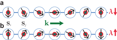
The spontaneous electric polarization, , is directed along one of the axes of the BFO pseudo-cubic (pc) cell and is associated with a ferroelastic distortion along the same direction, resulting in a rhombohedrally distorted perovskite structure. It has been shown that the polarization can be switched by , , or between the 8 possible directions, where switching by , is also accompanied by a switching of the ferroelastic state Zavaliche et al. (2006). Since the rhombohedral axis is unchanged when the polarization is switched by , the ferroelastic domain remains unchanged. The magnetic structure of BFO can be described locally as G-type but the spin-orbit interaction in the presence of the FE polarization drives an incommensurate cycloidal modulation of the spins (the direct Dzyaloshinksii-Moriya effect Kadomtseva et al. (2004)), rotating them in a plane containing . The propagation vector of the cycloid, , is always orthogonal to , and can take one of three symmetry equivalent directions in the rhombohedral lattice: . Here the subscript h denotes the hexagonal setting of the rhombohedral unit cell, and at . In the case of a cycloidal magnetic structure, the quadratic order parameter is the magnetic polarity, defined as where and are spins on adjacent sites (sequential in the direction of ), as depicted in Figure 1. This appears in a term in the Landau free energy expansion of the form , which couples the FE polarization to the magnetic structure.
II Experimental
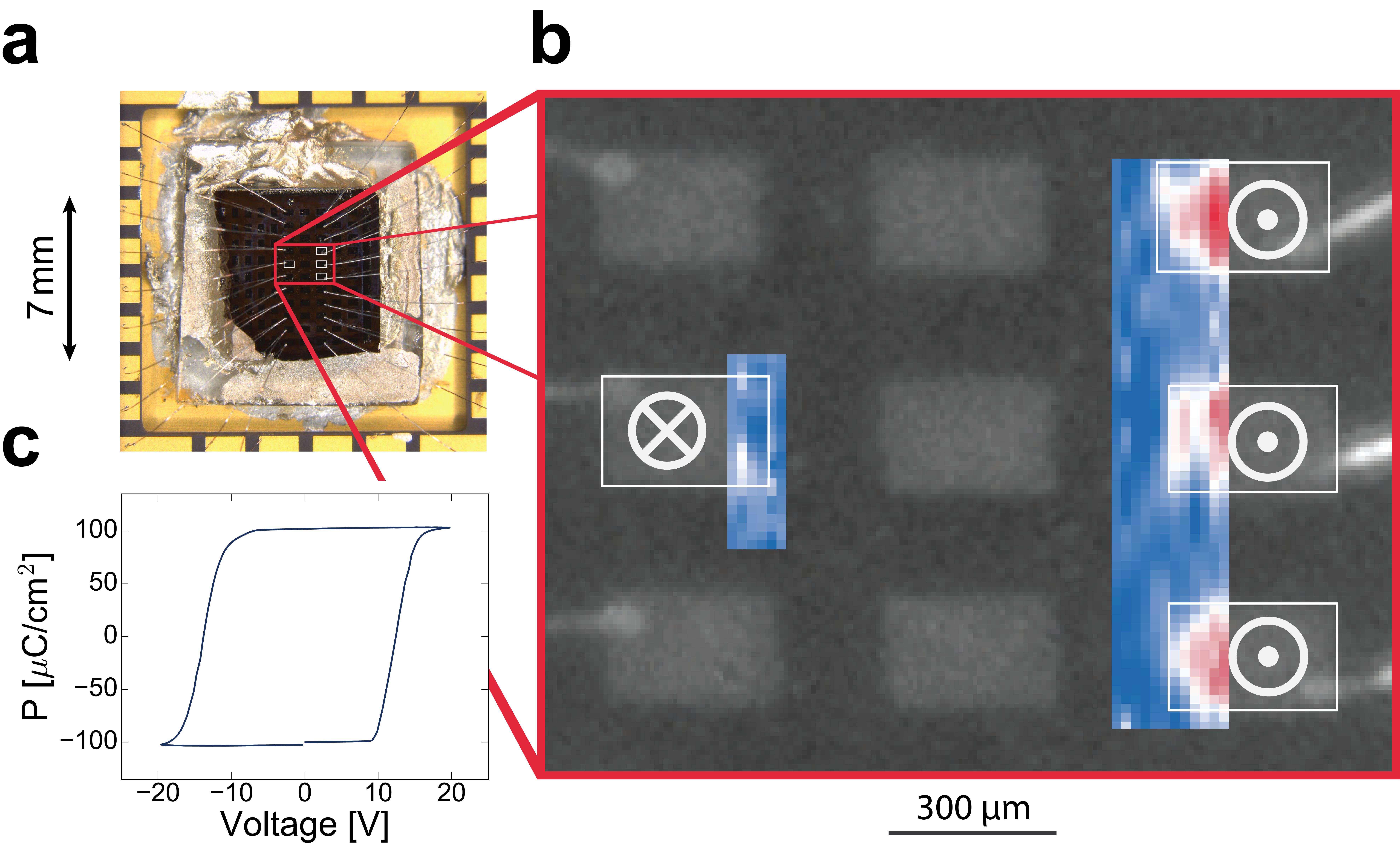
thick epitaxial films of BFO were grown by double gun off-axis sputtering onto a surface normal SrTiO3 single crystal substrate Das et al. (2006). A thick SrRuO3 layer was first deposited on the SrTiO3 substrate by off-axis sputtering before the BFO was grown, which serves as a bottom electrode Eom et al. (1992). x x Pt top electrodes were patterned on the surface of the film using photolithography, which were then wirebonded to a chip carrier [see fig. 2(a, b)]. This setup allows electric fields to be applied along the direction, perpendicular to the surface of the film. As shown in fig. 2(c) The films display excellent FE characteristics with a remnant polarization along the direction of , comparable to the highest reported literature values for oriented BFO films Das et al. (2006); Li et al. (2004); Bai et al. (2005). We label the FE domain with polarization directions along (surface normal, pointing out of the film) and (surface normal, pointing into the film) as FE and FE , respectively. The as-grown state of the film is a FE monodomain, as determined by piezoresponse force microscopy on other representative samples. Regions of the sample were switched into the FE polarization state prior to the experiment by applying a number of successive triangular waves (see Supplementary Material S-I Sup ) at , with a maximum voltage of . To test the reversibility of this process, we switched some of these regions back into the FE polarization state, using an inverted signal.
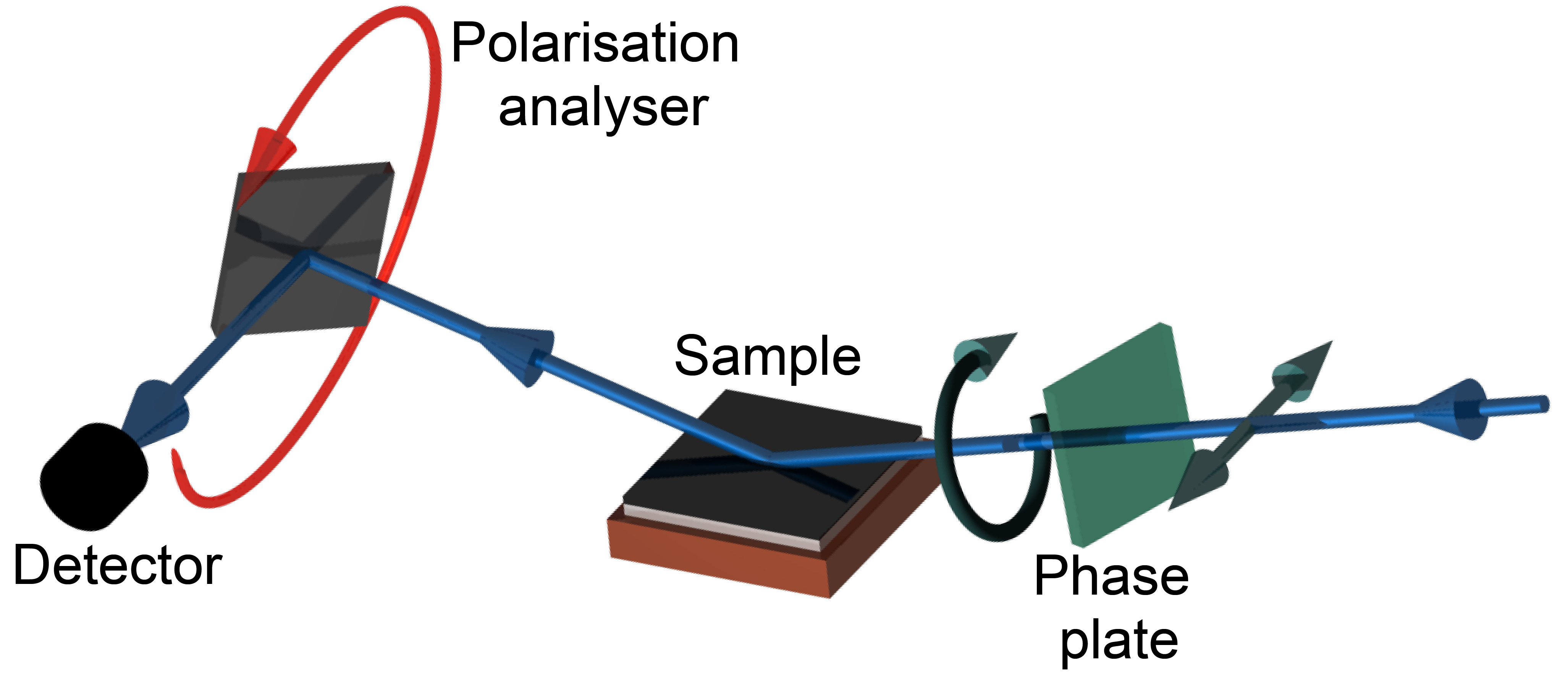
The magnetic state of the BFO film was probed by NXMS, which can measure the direction of propagation and periodicity of the spin cycloid, as well as the spin rotation plane. Using x-ray polarimetry, the magnetic polarity of the cycloidal magnetic structure may also be determined. The synchrotron NXMS experiments were performed on beamline I16 at Diamond Light Source (UK) using a six-circle kappa diffractometer in the reflection (vertical scattering) geometry, as shown in fig. 3. The incident x-ray beam energy was tuned to , which was selected for the following reasons: a) It was off-resonance of all chemical elements present in the sample. b) Absorption both by air and the Pt electrodes on the surface of the device was negligible. c) The probability of multiple scattering processes was reduced. Conversion of the incident x-ray polarization from -polarized x-rays to circularly polarized x-rays was achieved using a -thick diamond quarter-wave plate. The scattered x-ray polarization was determined using a pyrolitic graphite polarization analyser crystal scattering at the (004) reflection, built on the detector arm of the diffractometer such that any linear polarization channel may be selected. Measurements were taken at an azimuthal angle of with respect to the direction, identified as an experimental geometry in which multiple scattering was minimized.
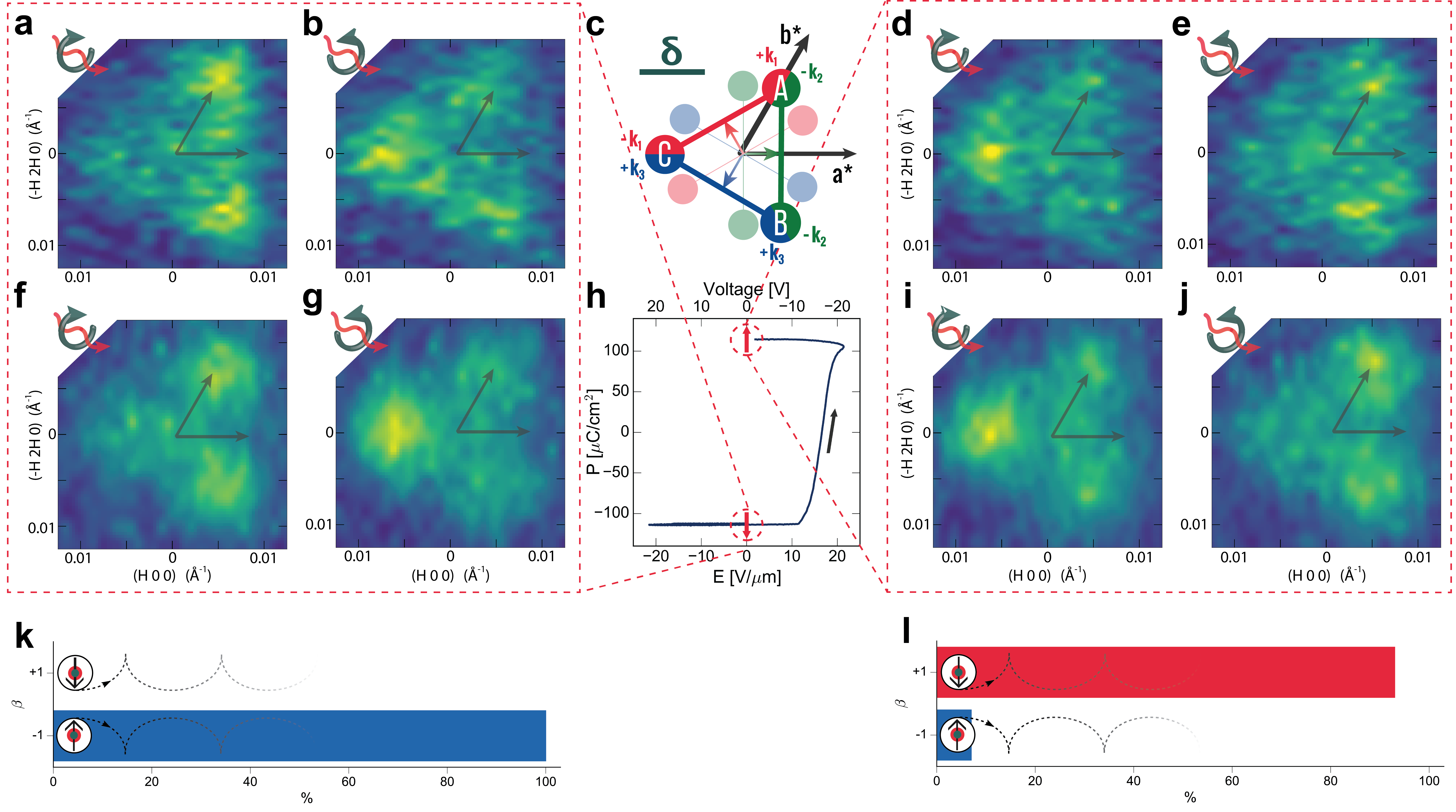
To determine cycloidal magnetic polarity, we measured by NXMS the magnetic satellite reflections which occur near the structurally-forbidden Bragg peak Waterfield Price et al. (2016) using circularly polarized x-rays. For a single magnetic domain with a propagation vector , the expected diffraction pattern is a pair of reflections located at . As shown in a previous x-ray magnetic linear dichroism photo-electron emission microscopy (XMLD-PEEM) study of an an identical -BFO film Waterfield Price et al. (2016), the typical domain size is , thus approximately equal populations of all three k-domains fall under the x-ray spot. In this case, one would expect to observe three pairs of peaks, as depicted by the lightly shaded circles in fig. 4(c). However, each magnetic domain is accompanied by a small monoclinic distortion, tilting the -plane in a direction orthogonal to . This moves the positions of the diffraction peaks such that they overlap, so that, instead of a star of six satellite peaks, only three composite peaks are observed Waterfield Price et al. (2016) as schematically shown in fig. 4(c).
III Results and discussion
For a given handedness of the incident beam polarization, the diffracted signal of the magnetic satellites is highly sensitive to the magnetic polarity of the magnetic domains illuminated by the x-ray spot. Figure 4(a) and (b) show, for a region of the sample in the ‘virgin’ FE state, reciprocal space maps of the magnetic satellites about the position for left circular and right circular polarized light, respectively. Figure 4(d) and (e) show the equivalent measurement on a region of the sample that has been switched into the FE state. We note that, as the diffraction intensity is centred at the same point in reciprocal space for the FE and FE states, both states are in the same pseudo-rhombohedral ferroelastic domain. The data agrees well with the corresponding simulations, shown in fig. 4(f,g) and fig. 4(i,j), respectively, and with previous measurements taken with higher statistics Waterfield Price et al. (2016). The simulations shown here are generated with the parameters obtained by simultaneously fitting all reciprocal space maps, with the population of the two magnetic polarity states allowed to freely refine, along with a global depolarization factor (see Supplemental Material S-II Sup ). Here, we have assumed equal populations of the three k-domains, which, for this direction of the incident polarization, leads to equal intensities for the left-hand pair of peaks (labeled and in fig. 4(c)). A theoretical intensity calculation for the composite magnetic peaks shown in fig. 4 yields
| (1) |
where the subscript denotes the individual peaks, labelled as , , and (see fig. 4(c)) and where or for left circular and right circular polarized light, respectively. The coupling between the magnetic polarity and FE polarization is parametrized by , where is the film surface normal. In agreement with a previous study on a bulk single crystal sample Johnson et al. (2013), we find that magnetic polarity of a given domain is aligned antiparallel to the FE polarization, hence or for the fully-polarized FE state and FE state, respectively.
As shown in fig. 4(k,l), the simultaneous fit of the reciprocal space maps yielded a switch of magnetic polarity from the virgin FE state to the FE state. The depolarization factor was found to be 0.194(4) (see Supplemental Material S-II Sup ), where this accounts for the imperfect circular polarization of the x-ray beam and contributions from any multiple scattering. The unswitched could be explained by a fraction of the film being pinned in the FE state, likely due to the bias at the BFO/SrRuO3 interface that stabilises a FE↓ monodomain in the as-grown BFO film Fong et al. (2006); Giencke et al. (2014). A small pinned fraction would not be detected in the FE polarisation measurement in fig. 4(h) since this measurement is relative i.e. there is an arbitrary offset in the magnitude of . Furthermore, although the majority of the beam intensity was focussed into an x footprint, low intensity tails of the beam will extend slightly beyond this so it is possible that a small portion of the surrounding film in the FE state was illuminated.
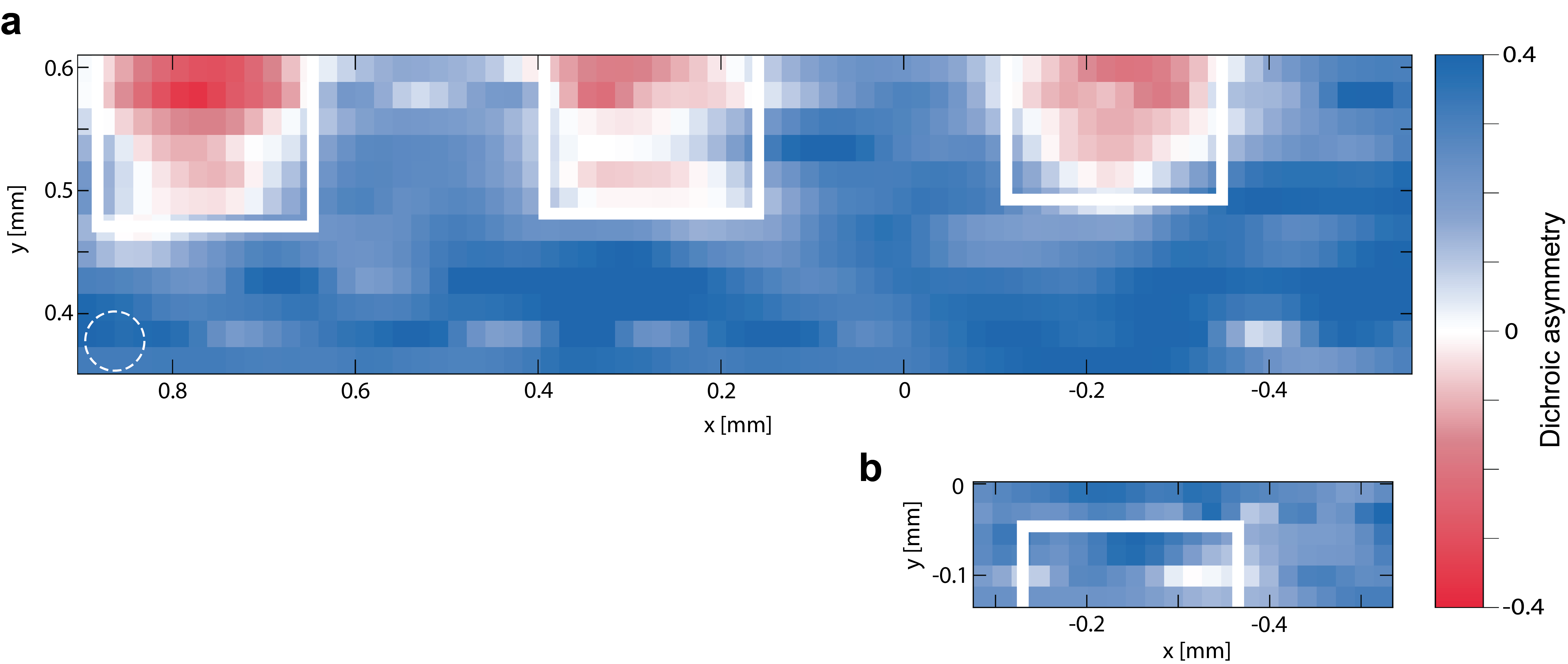
The response of the magnetic structure to electrical switching was further investigated by mapping in real space the magnetic polarity over an extended region of the device. Figure 5(a) and (b) show real space maps of an area of the sample containing regions that have been switched up and an area containing a region that has been switched up and then down again, respectively (see fig. 2(c)). These images were collected by rastering a x beam over the sample surface and recording the intensity of peak C at each point. The intensity was measured with both left-handed (lc) and right-handed (rc) circular polarization at every position. The maps were constructed by plotting the dichroic asymmetry, . In Figure 5(a) it is clear that, for the majority of the sample region which has been switched into the FE state, the magnetic polarity has also switched relative to the unswitched film in the FE state. The areas where the magnetic polarity appears not to have switched are concentrated around the edges of the switched electrodes. This can largely be explained by the resolution limitation of the measurement (indicated by the white dotted circle in fig. 5(a)), but it is also possible that electric-field edge effects resulted in incomplete FE switching at the outside of the pads. By contrast, the sample region below the electrical pad that has been switched into the FE state and then back into the FE state, has unchanged magnetic polarity relative to the surrounding region of unswitched BFO, indicating that the magnetic state is recovered entirely.
IV Conclusion
In summary, we have demonstrated electrical switching of magnetic polarity in a BFO device at room-temperature, a direct measurement of multiferroic coupling. The observed reversal of the magnetic polarity of the cycloid represents a major rearrangement of the magnetic structure, with magnetic moments rotating on average by upon switching. This is in contrast to the general belief that the coupling between magnetism and ferroelectricity is rather weak in Type-I multiferroics Khomskii (2009) but is in fact in full agreement with theoretical predictions Kadomtseva et al. (2004). Our experimental demonstration of polarity switching in a BFO device represents a crucial step towards developing full control of the interfacial exchange interactions in BFO-based composite multiferroic devices.
Acknowledgements
We acknowledge Diamond Light Source for time on Beam line I16 under Proposal MT12837-1. The work done at the University of Oxford (N.W.P., R.D.J., F.P.C., and P.G.R.) was funded by EPSRC grant No. EP/M020517/1, entitled “Oxford Quantum Materials Platform Grant.” The work at University of Wisconsin-Madison (C.B.E. and W.S.) was supported by the Army Research Office through grant W911NF-13-1-0486. R. D. J. acknowledges support from a Royal Society University Research Fellowship.
References
- Mostovoy (2006) Maxim Mostovoy, “Ferroelectricity in spiral magnets,” Physical Review Letters 96, 067601 (2006).
- Johnson et al. (2011) RD Johnson, Sunil Nair, LC Chapon, Alessandro Bombardi, Carlo Vecchini, D Prabhakaran, AT Boothroyd, and PG Radaelli, “Cu 3 nb 2 o 8: A multiferroic with chiral coupling to the crystal structure,” Physical review letters 107, 137205 (2011).
- Arima (2007) Taka-hisa Arima, “Ferroelectricity induced by proper-screw type magnetic order,” Journal of the Physical Society of Japan 76, 073702–073702 (2007).
- Chapon et al. (2004) LC Chapon, GR Blake, MJ Gutmann, S Park, N Hur, PG Radaelli, and SW Cheong, “Structural anomalies and multiferroic behavior in magnetically frustrated t b m n 2 o 5,” Physical review letters 93, 177402 (2004).
- Radaelli et al. (2008) P. G. Radaelli, L. C. Chapon, A. Daoud-Aladine, C. Vecchini, P. J. Brown, T. Chatterji, S. Park, and S. W. Cheong, “Electric field switching of antiferromagnetic domains in YMn2O5: A probe of the multiferroic mechanism,” Phys. Rev. Lett. 101, 067205 (2008).
- Yamasaki et al. (2007) Y. Yamasaki, H. Sagayama, T. Goto, M. Matsuura, K. Hirota, T. Arima, and Y. Tokura, “Electric control of spin helicity in a magnetic ferroelectric,” Phys. Rev. Lett. 98, 147204 (2007).
- Cabrera et al. (2009) I. Cabrera, M. Kenzelmann, G. Lawes, Y. Chen, W. C. Chen, R. Erwin, T. R. Gentile, J. B. Leao, J. W. Lynn, N. Rogado, R. J. Cava, and C. Broholm, “Coupled magnetic and ferroelectric domains in multiferroic Ni3V2O8,” Phys. Rev. Lett. 103, 087201 (2009).
- Fabrizi et al. (2010) F. Fabrizi, H. C. Walker, L. Paolasini, F. de Bergevin, T. Fennell, N. Rogado, R. J. Cava, T. Wolf, M. Kenzelmann, and D. F. McMorrow, “Electric field control of multiferroic domains in Ni3V2O8 imaged by x-ray polarization-enhanced topography,” Phys. Rev. B 82, 024434 (2010).
- Johnson et al. (2013) R. D. Johnson, P. Barone, A. Bombardi, R. J. Bean, S. Picozzi, P. G. Radaelli, Y. S. Oh, S. W. Cheong, and L. C. Chapon, “X-ray imaging and multiferroic coupling of cycloidal magnetic domains in ferroelectric monodomain BiFeO3,” Phys. Rev. Lett. 110, 217206 (2013).
- Hiraoka et al. (2011) Y. Hiraoka, Y. Tanaka, T. Kojima, Y. Takata, M. Oura, Y. Senba, H. Ohashi, Y. Wakabayashi, S. Shin, and T. Kimura, “Spin-chiral domains in Ba0.5Sr1.5Zn2 FeO observed by scanning resonant x-ray microdiffraction,” Phys. Rev. B 84, 064418 (2011).
- Zavaliche et al. (2006) F. Zavaliche, S. Y. Yang, T. Zhao, Y. H. Chu, M. P. Cruz, C. B. Eom, and R. Ramesh, “Multiferroic BiFeO3 films: domain structure and polarization dynamics,” Phase Transit. 79, 991 (2006).
- Lee et al. (2008) S. Lee, T. Choi, W. Ratcliff II, R. Erwin, S. W. Cheong, and V. Kiryukhin, “Single ferroelectric and chiral magnetic domain of single-crystalline BiFeO3 in an electric field,” Phys. Rev. B 78, 100101 (2008).
- Zhao et al. (2006) T. Zhao, A. Scholl, F. Zavaliche, K. Lee, M. Barry, A. Doran, M. P. Cruz, Y. H. Chu, C. E rer, N. A. Spaldin, R. R. Das, D. M. Kim, S. H. Baek, C. B. Eom, and R. Ramesh, “Electrical control of antiferromagnetic domains in multiferroic BiFeO3 films at room temperature,” Nat. Mat. 5, 823 (2006).
- Lebeugle et al. (2008) D. Lebeugle, D. Colson, A. Forget, M. Viret, A. M. Bataille, and A. Gukasov, “Electric-field-induced spin flop in BiFeO3 single crystals at room temperature,” Phys. Rev. Lett. 100, 227602 (2008).
- Sando et al. (2013) D Sando, A Agbelele, D Rahmedov, J Liu, P Rovillain, C Toulouse, IC Infante, AP Pyatakov, S Fusil, E Jacquet, et al., “Crafting the magnonic and spintronic response of bifeo3 films by epitaxial strain,” Nature materials 12, 641–646 (2013).
- Chu et al. (2008) Ying-Hao Chu, Lane W Martin, Mikel B Holcomb, Martin Gajek, Shu-Jen Han, Qing He, Nina Balke, Chan-Ho Yang, Donkoun Lee, Wei Hu, et al., “Electric-field control of local ferromagnetism using a magnetoelectric multiferroic,” Nature materials 7, 478–482 (2008).
- Béa et al. (2008) H Béa, M Bibes, F Ott, B Dupé, X-H Zhu, S Petit, S Fusil, C Deranlot, K Bouzehouane, and A Barthélémy, “Mechanisms of exchange bias with multiferroic bifeo 3 epitaxial thin films,” Physical review letters 100, 017204 (2008).
- Lebeugle et al. (2010) D Lebeugle, A Mougin, M Viret, D Colson, J Allibe, H Béa, E Jacquet, C Deranlot, M Bibes, and A Barthélémy, “Exchange coupling with the multiferroic compound bifeo 3 in antiferromagnetic multidomain films and single-domain crystals,” Physical Review B 81, 134411 (2010).
- Heron et al. (2011) J. T. Heron, M. Trassin, K. Ashraf, M. Gajek, Q. He, S. Y. Yang, D. E. Nikonov, Y. H. Chu, S. Salahuddin, and R. Ramesh, “Electric-field-induced magnetization reversal in a ferromagnet-multiferroic heterostructure,” Phys. Rev. Lett. 107, 217202 (2011).
- Heron et al. (2014) J. T. Heron, J. L. Bosse, Q. He, Y. Gao, M. Trassin, L. Ye, J. D. Clarkson, C. Wang, Jian Liu, S. Salahuddin, D. C. Ralph, D. G. Schlom, J. Iniguez, B. D. Huey, and R. Ramesh, “Deterministic switching of ferromagnetism at room temperature using an electric field,” Nature 516, 370 (2014).
- Sando et al. (2014) D Sando, A Barthélémy, and M Bibes, “Bifeo3 epitaxial thin films and devices: past, present and future,” Journal of Physics: Condensed Matter 26, 473201 (2014).
- Gao et al. (2016) TR Gao, XH Zhang, W. Ratcliff II, S Maruyama, M Murakami, V Anbusathaiah, Z Yamani, PJ Chen, R Shull, R Ramesh, et al., “Electric-field induced reversible switching of the magnetic easy-axis in co/bifeo3/srruo3/srtio3 heterostructures,” arXiv preprint arXiv:1611.07482 (2016).
- Kadomtseva et al. (2004) A. M. Kadomtseva, A. K. Zvezdin, Y. F. Popov, A. P. Pyatakov, and G. P. Vorob’ev, “Space-time parity violation and magnetoelectric interactions in antiferromagnets,” JETP Lett. 79, 571 (2004).
- Das et al. (2006) R. R. Das, D. M. Kim, S. H. Baek, C. B. Eom, F. Zavaliche, S. Y. Yang, R. Ramesh, Y. B. Chen, X. Q. Pan, X. Ke, M. S. Rzchowski, and S. K. Streiffer, “Synthesis and ferroelectric properties of epitaxial BiFeO3 thin films grown by sputtering,” Appl. Phys. Lett 88, 242904 (2006).
- Eom et al. (1992) C. B. Eom, R. J. Cava, R. M. Fleming, J. M. Phillips, R. B. Vandover, J. H. Marshall, J. W. Hsu, J. J. Krajewski, and W. F. Peck, “Single-crystal epitaxial thin films of the isotropic metallic oxides SrxCaRuO3 (),” Science 258, 1766 (1992).
- Li et al. (2004) J. Li, J. Wang, M. Wuttig, R. Ramesh, N. Wang, B. Ruette, A. P. Pyatakov, A. K. Zvezdin, and D. Viehland, “Dramatically enhanced polarization in (001),(101), and (111) BiFeO3 thin films due to epitiaxial-induced transitions,” Appl. Phys. Lett. 84, 5261 (2004).
- Bai et al. (2005) F. Bai, J. Wang, M. Wuttig, J. Li, N. Wang, A. P. Pyatakov, A. K. Zvezdin, L. E. Cross, and D. Viehland, “Destruction of spin cycloid in (111) c-oriented BiFeO3 thin films by epitiaxial constraint: enhanced polarization and release of latent magnetization,” Appl. Phys. Lett. 86, 032511 (2005).
- (28) See Supplemental Material at [URL will be inserted by publisher], which includes Refs. Waterfield Price et al. (2016); Blume and Gibbs (1988) for further information on the preparation of the ferroelectric state of the sample and details of the non-resonant x-ray magnetic scattering data analysis.
- Waterfield Price et al. (2016) N. Waterfield Price, R. D. Johnson, W. Saenrang, F. Maccherozzi, S. S. Dhesi, A. Bombardi, F. P. Chmiel, C. B. Eom, and P. G. Radaelli, “Coherent magnetoelastic domains in multiferroic BiFeO3 films,” Phys. Rev. Lett. 117, 177601 (2016).
- Fong et al. (2006) DD Fong, AM Kolpak, JA Eastman, SK Streiffer, PH Fuoss, GB Stephenson, Carol Thompson, DM Kim, Kyoung Jin Choi, CB Eom, et al., “Stabilization of monodomain polarization in ultrathin pbtio 3 films,” Physical review letters 96, 127601 (2006).
- Giencke et al. (2014) Jon E Giencke, Chad M Folkman, Seung-Hyub Baek, and Chang-Beom Eom, “Tailoring the domain structure of epitaxial bifeo 3 thin films,” Current Opinion in Solid State and Materials Science 18, 39–45 (2014).
- Khomskii (2009) D. Khomskii, “Trend: Classifying multiferroics: Mechanisms and effects,” Physics 2, 20 (2009).
- Blume and Gibbs (1988) M Blume and D Gibbs, “Polarization dependence of magnetic x-ray scattering,” Physical Review B 37, 1779 (1988).