Quantum interface between photonic and superconducting qubits
Abstract
We show that optically active coupled quantum dots embedded in a superconducting microwave cavity can be used to realize a fast quantum interface between photonic and transmon qubits. Single photon absorption by a coupled quantum dot results in generation of a large electric dipole, which in turn ensures efficient coupling to the microwave cavity. Using cavity parameters achieved in prior experiments, we estimate that bi-directional microwave-optics conversion in nanosecond timescales with efficiencies approaching unity is experimentally feasible with current technology. We also outline a protocol for in-principle deterministic quantum state transfer from a time-bin photonic qubit to a transmon qubit. Recent advances in quantum dot based quantum photonics technologies indicate that the scheme we propose could play a central role in connecting quantum nodes incorporating cavity-coupled superconducting qubits.
pacs:
Introduction.
A quantum interface between flying photonic and stationary matter qubits is widely regarded as an essential element of quantum networks Kimble (2008); Cirac et al. (1997, 1999). Remarkable advances over the last decade have established that circuit-QED, consisting of superconducting (SC) qubits non-perturbatively coupled to a common microwave (MW) cavity, is particularly promising for realization of small-scale quantum information processors Nakamura et al. (1999); Devoret and Schoelkopf (2013). The most prominent limitation in realization of quantum networks consisting of circuit-QED based processors is the difficulty in transferring quantum information over distances exceeding meters. Motivated by overcoming this roadblock, several groups have embarked on research aimed at creating a quantum interface between SC qubits and propagating photonic qubits. Among the several ingenuous proposals Strekalov et al. (2009); Rueda et al. (2016); Hafezi et al. (2012); Petrosyan et al. (2009); Williamson et al. (2014); Fernandez-Gonzalvo et al. (2015); Imamoğlu (2009); Blum et al. (2015); Hisatomi et al. (2016); Das et al. (2017) to resolve this conundrum, the approach based on using optomechanical coupling Tian (2015); Bochmann et al. (2013); Balram et al. (2016); Bagci et al. (2014); Andrews et al. (2014) has proven to be particularly successful: pioneering experiments have demonstrated conversion efficiency of with a bandwidth of Andrews et al. (2014). A limitation for most if not all of these approaches is the relatively small effective coupling strength between the single optical and MW photons, which in turn prevents conversion of quantum information on time-scales much shorter than typical SC qubit coherence times.
In this Letter, we propose a novel quantum interface consisting of a coupled quantum dot (CQD) embedded in a low-Q optical cavity and positioned at the antinode of a high-Q SC MW resonator. Unlike the aforementioned hybrid quantum systems, CQDs in integrated structures such as the one depicted in Fig. 1 have large coupling strengths to both optical and MW fields, which ensures fast and high-efficiency bi-directional MW-to-optics conversion. Three key features of the scheme we detail are (i) the use of low-Q asymmetric optical cavity to allow for high-efficiency absorption of an incoming single-photon pulse; (ii) the creation of a large electric dipole in the CQD by absorption of a single photon ensuring strong coupling to the MW resonator; and (iii) fast radiative decay rate of the CQD optical transitions yielding nanosecond time-scale inter-conversion. After presenting a detailed analysis of the quantum interface between MW and optical photons, we describe a scheme for quantum state transfer from an incident flying photon qubit to a SC transmon qubit via the MW resonator.
Structure of the interface and coupling between microwave and optical photons.
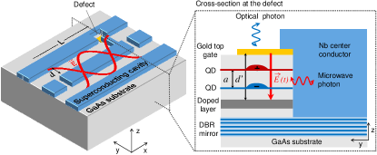
Figure 1 shows the structure that we analyze: the substrate of the SC cavity is an MBE grown GaAs sample consisting of a Distributed Bragg Reflector (DBR) mirror, an n++-GaAs section and a layer of InGaAs CQDs. Before fabrication of the SC coplanar resonator by Nb deposition, the top section of the GaAs substrate containing the n++-GaAs section and the CQDs is etched away to reduce MW losses. To ensure efficient CQD-MW coupling while minimizing MW losses, a defect region of width m is introduced at one of the resonator antinodes (Fig. 1): it is only in this small area region of the device that the layers containing CQDs and the n++-GaAs section are not etched away. The top gold layer in the defect, connected to the Nb center conductor, acts as a top gate for adjusting the CQD energy levels to ensure optimal optical coupling and dipole generation. Concurrently, this top nm gold layer, together with the bottom DBR mirror forms a low-Q optical cavity that ensures efficient interface between the CQD and the single-photon pulses Delley et al. .
We remark that the device depicted in Fig. 1 is motivated by the structure successfully used to demonstrate strong coupling between an electrically defined GaAs CQD charge qubit and an Al coplanar resonator Frey et al. (2012); Stockklauser et al. (2017). In these experiments, MW resonator Q-factors of several thousands were demonstrated in structures with a defect region incorporating a two-dimensional electron system (2DES). In parallel, large single-photon absorption induced electric dipoles have been demonstrated using CQDs that allow for electric field control of coherent resonant tunneling between the two QDs comprising the CQD Krenner et al. (2005). As a result, the use of high impedance SC cavity with vacuum-field enhancement at the location of the CQD would enable efficient coupling of the large CQD dipole to the SC cavity (up to MHz, see Supplemental Material). Finally, low-Q optical cavities with a leaky top mirror have been used in experiments demonstrating distant quantum dot (QD) spin entanglement Delteil et al. (2016) as well as absorption of a photonic qubit by a single QD Delteil et al. (2017). The low-Q cavity modifies the radiation pattern of the CQD and provides an excellent match to the Gaussian profile of the incident photon mode, thereby ensuring efficient absorption of the optical photons.
Single photon conversion.
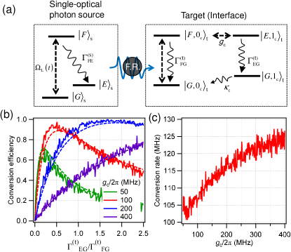
To analyze conversion of a single optical photon pulse into a MW cavity photon, we consider a QD single photon source (labeled ) whose output is channeled to a target CQD (labeled ) that is embedded under the defect region of the SC resonator. Figure 2(a) shows the energy level diagram of the source QD (left) and the target CQD (right). A single photon pulse is generated on the to transition: the laser pulse with Rabi frequency exciting the QD from to determines the pulse shape. The transition energies are adjusted using electric and magnetic fields to ensure that the center frequency of the single-photon pulse matches the to transition of the target CQD Delteil et al. (2017). To simplify the analysis, we assume that either a Faraday rotator or a chiral waveguide is placed in between the source and target QDs; this assumption allows us to use the cascaded quantum systems formalism to calculate the conversion efficiency in the limit of low-loss photon transfer Carmichael (1993); Gardiner (1993); Pinotsi and Imamoglu (2008).
We assume that the target CQD is neutral and its energy levels are tuned using an external gate voltage to ensure coherent tunnel coupling between the lowest electronic states of the top and bottom QDs. The resulting symmetric and antisymmetric excitonic states are labeled and , respectively. Furthermore, we assume that - splitting matches the SC resonator resonance frequency. The sequence for optics-to-MW conversion is then
where denotes the single-MW-photon eigenstate of the SC resonator. and denote the single-photon pulses generated by the source QD and the target CQD, respectively.
We calculate the efficiency and speed of the conversion process, determined by the CQD-resonator coupling strength as well as the spontaneous emission rates, using the quantum Monte Carlo method Carmichael (1993); Pinotsi and Imamoglu (2008) (see the supplemental material for a detailed description of the calculation). Since generation of a target photon upon spontaneous emission on the transition heralds successful optical-MW photon conversion, we determine the number of these photon emission events in quantum trajectory simulations to estimate the conversion efficiency and rate.
Figure 2(b) shows the conversion efficiency (solid curves) as a function of a ratio for various . The efficiency rapidly increases as increases from 0 and reaches a maximum at a certain . We attribute this dependence to a quantum interference between the incident single-photon pulse and the secondary field generated at the same frequency by the target CQD (see the Supplemental Material). When photon detection at the transition is suppressed due to this destructive interference, the efficiency reaches its maximum value. One can see that the maximum shifts to larger ratios and approaches unity as we increase .
To obtain an analytical expression valid in the limit of purely coherent light scattering (see Supplemental Material), we note that the conversion efficiency can be expressed as
| (1) |
where is the normalized mean field generated at the transition and is given by
| (2) |
assuming SC cavity decay rate is much smaller than and all spontaneous emission rates. The dashed lines in Fig. 2(b) are the analytical results. Here, is the effective decay rate from to . The real part of Eq. (2) expresses the quantum interference. If the two decay rates and are equal, the reflection is suppressed, i.e. the efficiency is maximal. The imaginary part accounts for the frequency detuning between the incident photon and which is shifted by due to the MW coupling. This detuning limits the maximum efficiency when as shown in Fig. 2(b). In practice, it is possible to restore the efficiency in the limit of large to almost unity by tuning the frequency of the incident photon. The condition for the efficient conversion is, therefore, . For , satisfies this condition, and the efficiency approaches unity.
We plot the calculated conversion rate, defined as the reciprocal of the time required to complete the transfer, in Fig. 2(c) as a function of at . The rate becomes larger as is increased. When , the conversion rate is about 110 MHz.
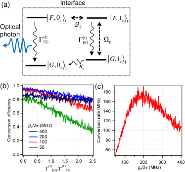
Next, we consider the reverse process of frequency conversion of single SC resonator MW photon to a propagating single-photon pulse. Figure 3(a) depicts the energy level diagram of the CQD used to realize the quantum interface, which is identical to that of the target CQD in Fig. 1. In contrast to the previous discussion, we now assume that the system starts out in state and is excited by a laser field tuned into resonance with the transition. We emphasize that a fundamental limitation on the conversion efficiency stems from the SC resonator decay rate . In the limit where MW-assisted laser up-conversion rate is much larger than , conversion efficiency will approach unity. The ratio determines the number of photons scattered on the transition before MW-to-optical photon conversion is successful. If the latter photons are not detected, the indistinguishability of the generated single optical photon pulse will be compromised. Figure 3(b) shows the dependence of the conversion efficiency as a function of , determined by counting the number of photon emission events at the transition in quantum trajectory simulations. For , conversion efficiencies exceeding can be reached even for MHz. We emphasize that in this limit we expect the generated photons to be highly indistinguishable.
Figure 3(c) shows the conversion rate as a function of at . For , the rate increases with increasing and reaches about 170 MHz at . This behavior follows the rate . The rate decreases for due to the detuning of the laser field from the transition; as we argued before, this reduction does not represent a real limitation and can be remedied by adjusting the incident laser frequency. For , leads to an efficiency of with a conversion rate of 170 MHz.
Quantum state transfer.
The bi-directional single photon conversion enabled by the device we propose opens the way for transferring quantum information from a photonic qubit to a SC qubit coupled to the MW cavity, and vice-versa. In the following we propose a protocol realizing such transfer from a time-bin photonic qubit to a transmon qubit. The use of time-bin qubits enables the use of the aforementioned conversion process without modifications, and does not rely on additional local degrees of freedom of the CQD and/or the SC cavity. Commonly used photonic qubits (polarization qubits, dual rail qubits) can be straightforwardly converted into time-bin qubits using linear optics. Finally, while we assume a transmon qubit, any SC qubit with an anharmonic spectrum could be employed.
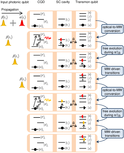
Figure 4(a) depicts the transfer protocol. The system we consider is almost identical to the device shown in Fig. 1; the only modification is the addition of a transmon qubit coupled to the cavity. We consider the first four levels of the anharmonic qubit spectrum: the ground state and the three first excited states , and . The transition is resonant with the cavity mode, with a coupling strength satisfying Suri et al. (2015). moreover, we assume that resonant MW pulses can be applied to drive coherent rotations within the three pairs of successive states of the transmon qubit Peterer et al. (2015). The input photonic state is a time-bin qubit of the form , with and denoting the arrival time of the two components of the qubit. The transmon qubit is initially in . Within a few nanoseconds after , the component is transferred to a MW cavity photon with probability amplitude . The coupled cavity-transmon system will then start to undergo Rabi oscillations at frequency . After half a Rabi oscillation period, the MW cavity population is swapped with that of the state of the transmon. At this point, we apply a -pulse resonant with the transition followed by a second -pulse resonant with the transition, which coherently transfers the population onto the state within a few nanoseconds. Similarly, after the probability amplitude of the second component of the qubit is mapped onto the state using coherent transfer from to followed by a -pulse driving the transition. The final state of the transmon is . In addition, in case of finite transfer efficiency, an unsuccessful transfer process will be associated with finite population of the transmon ground state, whose readout acts as a syndrome measurement for a failed transfer. The total duration of the state transfer can be as short as a few tens of nanoseconds – much shorter than the coherence time of the transmon qubits (typically several 10s to 100s of microseconds Koch et al. (2007); Chang et al. (2013); Rigetti et al. (2012); Paik et al. (2011); Barends et al. (2013)). In our scheme, population transfer into the subspace of the transmon allows to decouple the qubit from the MW cavity. The two lower energy states can however be used to store the final state provided that the cavity is tuned away from the transition once the transfer is achieved. An alternative way to transfer the MW cavity population to the transmon, rather than using the excited transmon states, is to make use of several transmon qubits and perform SWAP operation between them to store transferred populations Dewes et al. (2012).
We remark that an optical-to-MW photon conversion process leads to subsequent emission of a photon from the transition of the CQD. Hence after the transfer, the state of the transmon qubit will be entangled with the time-bin degree of freedom of the emitted photon, leading to leakage of which-path information. This qubit-photon entanglement can be used as a resource for generation of entanglement between distant nodes. For the purpose of quantum state transfer, it is possible to erase this entanglement by delaying the first component of the emitted photon by and then erase the which-path information by combining the the two paths using a beam-splitter (see Supplemental Material). In case of finite optical losses and/or finite detection efficiencies, such a scheme will not succeed all the time but success will be heralded.
The reciprocal transmon-to-photonic qubit transfer process can be realized using a reverse sequence: the first step in the protocol is the transfer of the amplitudes in and using a sequence of MW -pulses applied at and , which allows for generation of a finite probability amplitude for a single-MW-photon state due to coherent transmon-cavity interaction. The MW-to-optical photon conversion described earlier is used in the second step to successively upconvert the MW-photon to the optical domain, ensuring faithful state transfer to a time-bin photonic qubit.
In summary, we proposed a device realizing coherent bi-directional photon conversion using CQD coupled with a MW resonator. Simulations based on quantum Monte Carlo method reveal conversion rates up to hundreds of MHz with close-to-unity conversion efficiencies for both up- and down-conversion. The requisite cavity-CQD coupling strengths can be achieved by using a high impedance SC cavity Stockklauser et al. (2017) and enhancing the cavity vacuum electric field at the location of the CQD (see Supplemental Material). By adding a transmon qubit coupled to the same SC cavity, we show that quantum state transfer from photonic qubit to transmon qubit is achievable at rates of several tens of MHz. We believe that such a structure would open the way to high bandwidth quantum networks consisting of SC-qubit-based nodes remotely connected by optical photons.
Acknowledgements.
Y.T., P.K., and A.D. contributed equally to this work. This work is supported by NCCR Quantum Photonics (NCCR QP), research instrument of the Swiss National Science Foundation (SNSF), and by by Swiss NSF under Grant No. 200020-159196.References
- Kimble (2008) H. J. Kimble, Nature 453, 1023 (2008).
- Cirac et al. (1997) J. I. Cirac, P. Zoller, H. J. Kimble, and H. Mabuchi, Phys. Rev. Lett. 78, 3221 (1997).
- Cirac et al. (1999) J. I. Cirac, A. K. Ekert, S. F. Huelga, and C. Macchiavello, Phys. Rev. A 59, 4249 (1999).
- Nakamura et al. (1999) Y. Nakamura, Y. A. Pashkin, and J. S. Tsai, Nature 398, 786 (1999).
- Devoret and Schoelkopf (2013) M. H. Devoret and R. J. Schoelkopf, Science 339, 1169 (2013).
- Strekalov et al. (2009) D. V. Strekalov, H. G. L. Schwefel, A. A. Savchenkov, A. B. Matsko, L. J. Wang, and N. Yu, Phys. Rev. A 80, 033810 (2009).
- Rueda et al. (2016) A. Rueda, F. Sedlmeir, M. C. Collodo, U. Vogl, B. Stiller, G. Schunk, D. V. Strekalov, C. Marquardt, J. M. Fink, O. Painter, et al., Optica 3, 597 (2016).
- Hafezi et al. (2012) M. Hafezi, Z. Kim, S. L. Rolston, L. A. Orozco, B. L. Lev, and J. M. Taylor, Phys. Rev. A 85, 020302 (2012).
- Petrosyan et al. (2009) D. Petrosyan, G. Bensky, G. Kurizki, I. Mazets, J. Majer, and J. Schmiedmayer, Phys. Rev. A 79, 040304 (2009).
- Williamson et al. (2014) L. A. Williamson, Y.-H. Chen, and J. J. Longdell, Phys. Rev. Lett. 113, 203601 (2014).
- Fernandez-Gonzalvo et al. (2015) X. Fernandez-Gonzalvo, Y.-H. Chen, C. Yin, S. Rogge, and J. J. Longdell, Phys. Rev. A 92, 062313 (2015).
- Imamoğlu (2009) A. Imamoğlu, Phys. Rev. Lett. 102, 083602 (2009).
- Blum et al. (2015) S. Blum, C. O’Brien, N. Lauk, P. Bushev, M. Fleischhauer, and G. Morigi, Phys. Rev. A 91, 033834 (2015).
- Hisatomi et al. (2016) R. Hisatomi, A. Osada, Y. Tabuchi, T. Ishikawa, A. Noguchi, R. Yamazaki, K. Usami, and Y. Nakamura, Phys. Rev. B 93, 174427 (2016).
- Das et al. (2017) S. Das, V. E. Elfving, S. Faez, and A. S. Sørensen, Phys. Rev. Lett. 118, 140501 (2017).
- Tian (2015) L. Tian, Ann. Phys. 527, 1 (2015).
- Bochmann et al. (2013) J. Bochmann, A. Vainsencher, D. D. Awschalom, and A. N. Cleland, Nat. Phys. 9, 712 (2013).
- Balram et al. (2016) K. C. Balram, M. I. Davanço, J. D. Song, and K. Srinivasan, Nat. photonics 10, 346 (2016).
- Bagci et al. (2014) T. Bagci, A. Simonsen, S. Schmid, L. G. Villanueva, E. Zeuthen, J. Appel, J. M. Taylor, A. Sørensen, K. Usami, A. Schliesser, et al., Nature 507, 81 (2014).
- Andrews et al. (2014) R. W. Andrews, R. W. Peterson, T. P. Purdy, K. Cicak, R. W. Simmonds, C. A. Regal, and K. W. Lehnert, Nat. Phys. 10, 321 (2014).
- (21) Y. Delley, M. Kroner, S. Fält, W. Wegscheider, and A. Imamoğlu, arXiv:1704.01033 .
- Frey et al. (2012) T. Frey, P. Leek, M. Beck, A. Blais, T. Ihn, K. Ensslin, and A. Wallraff, Phys. Rev. Lett. 108, 046807 (2012).
- Stockklauser et al. (2017) A. Stockklauser, P. Scarlino, J. V. Koski, S. Gasparinetti, C. K. Andersen, C. Reichl, W. Wegscheider, T. Ihn, K. Ensslin, and A. Wallraff, Phys. Rev. X 7, 011030 (2017).
- Krenner et al. (2005) H. J. Krenner, M. Sabathil, E. C. Clark, A. Kress, D. Schuh, M. Bichler, G. Abstreiter, and J. J. Finley, Phys. Rev. Lett. 94, 057402 (2005).
- Delteil et al. (2016) A. Delteil, Z. Sun, W. Gao, E. Togan, S. Fält, and A. Imamoğlu, Nat. Phys. 12, 218 (2016).
- Delteil et al. (2017) A. Delteil, Z. Sun, S. Fält, and A. Imamoğlu, Phys. Rev. Lett. 118, 177401 (2017).
- Carmichael (1993) H. J. Carmichael, Phys. Rev. Lett. 70, 2273 (1993).
- Gardiner (1993) C. W. Gardiner, Phys. Rev. Lett. 70, 2269 (1993).
- Pinotsi and Imamoglu (2008) D. Pinotsi and A. Imamoglu, Phys. Rev. Lett. 100, 093603 (2008).
- Suri et al. (2015) B. Suri, Z. K. Keane, L. S. Bishop, S. Novikov, F. C. Wellstood, and B. S. Palmer, Phys. Rev. A 92, 063801 (2015).
- Peterer et al. (2015) M. J. Peterer, S. J. Bader, X. Jin, F. Yan, A. Kamal, T. Gudmundsen, P. J. Leek, T. P. Orlando, W. D. Oliver, and S. Gustavsson, Phys. Rev. Lett. 114, 010501 (2015).
- Koch et al. (2007) J. Koch, T. M. Yu, J. Gambetta, A. A. Houck, D. I. Schuster, J. Majer, A. Blais, M. H. Devoret, S. M. Girvin, and R. J. Schoelkopf, Phys. Rev. A 76, 042319 (2007).
- Chang et al. (2013) J. B. Chang, M. R. Vissers, A. D. Córcoles, M. Sandberg, J. Gao, D. W. Abraham, J. M. Chow, J. M. Gambetta, M. B. Rothwell, G. A. Keefe, et al., App. Phys. Lett. 103, 012602 (2013).
- Rigetti et al. (2012) C. Rigetti, J. M. Gambetta, S. Poletto, B. L. T. Plourde, J. M. Chow, A. D. Córcoles, J. A. Smolin, S. T. Merkel, J. R. Rozen, G. A. Keefe, et al., Phys. Rev. B 86, 100506 (2012).
- Paik et al. (2011) H. Paik, D. I. Schuster, L. S. Bishop, G. Kirchmair, G. Catelani, A. P. Sears, B. R. Johnson, M. J. Reagor, L. Frunzio, L. I. Glazman, et al., Phys. Rev. Lett. 107, 240501 (2011).
- Barends et al. (2013) R. Barends, J. Kelly, A. Megrant, D. Sank, E. Jeffrey, Y. Chen, Y. Yin, B. Chiaro, J. Mutus, C. Neill, et al., Phys. Rev. Lett. 111, 080502 (2013).
- Dewes et al. (2012) A. Dewes, F. R. Ong, V. Schmitt, R. Lauro, N. Boulant, P. Bertet, D. Vion, and D. Esteve, Phys. Rev. Lett. 108, 057002 (2012).