Hardware and software architecture of the upgraded H.E.S.S. cameras
Abstract:
In 2015/16, the photomultiplier cameras of the H.E.S.S. Cherenkov telescopes CT1-4 have undergone a major upgrade. The entire electronics has been replaced, using NECTAr chips for the front-end readout. A new ventilation system has been installed and several auxiliary components have been replaced. Besides this, the internal control and readout software was rewritten from scratch in a modern and modular way. Ethernet technology was used wherever possible to ensure both flexibility, stability and high bandwidth. An overview of the installed components will be given.
1 Introduction
The H.E.S.S. experiment is located in the Khomas Highland of Namibia [1]. From January 2004 to July 2012, it consisted of an array of four 12-meter Imaging Atmospheric Cherenkov Telescopes (IACTs) named CT1-4. They form a square with a side length of , have an effective mirror area of , detect cosmic gamma rays in the to energy range, and cover a field of view of in diameter. In July 2012, a fifth telescope (CT5) with a much larger mirror was commissioned. It provides a lower threshold of around and a higher event rate of . Operated in coincidence mode with the smaller CT1-4, this would have allowed also for a lower stereoscopic threshold of the entire array, but the readout dead time of the CT1-4 cameras [2] was , which did not allow for a substantial lowering of the trigger threshold.
The primary goal of the upgrade of the CT1-4 cameras presented here was therefore to reduce the dead time of the cameras when operating with CT5. Another aspect was to reduce the downtime of the cameras: after a decade of operation in the Namibian Savannah, with its harsh environment, the failure rate had begun to increase and a redesign of the cameras with an enhanced filtered ventilation system had become desirable to stabilise operations.
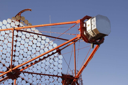
The first new camera was installed in July 2015 in the CT1 telescope (see Fig. 1, left). After its extensive testing and validation, the other three cameras were produced and installed already in September 2016. Since February 2017, all four cameras are in routine operation and part of the H.E.S.S. observation program.
The following will report about the deployed hardware and software of the new components. The performance is described in more detail in a second contribution to this conference [3].
2 Hardware architecture
2.1 Electronic front end
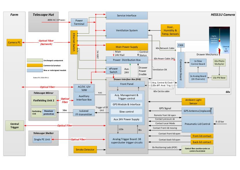
In the course of the camera upgrade, almost every component inside the camera was replaced, except for the photomultiplier tubes (PMTs), their high voltage bases and the calibration units. A scheme of the logical blocks of the new cameras and their interplay can be seen in Fig. 2.
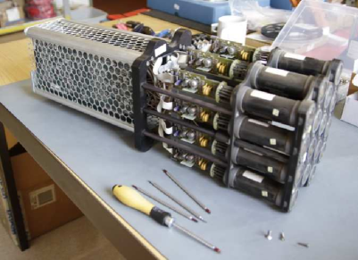
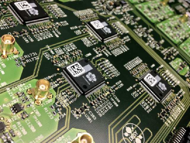
The most important element of the upgraded cameras contributing to the reduction of the dead time is the readout, built around the NECTAr analog memory chip [4]. It is located in the front-end part of the camera where Cherenkov light from particle showers in the atmosphere is detected and digitized. The light sensors are 960 PMTs, sorted into modules called drawers (Fig. 3, left), which consist of 16 PMTs each and which are also responsible for the amplification and readout of the PMT signals. A drawer consists of two analogue boards (Fig. 3, right), each hosting 8 analogue channels. They are mounted vertically on top of a slow control board, which is located at the bottom of the drawer. Each slow control board is connected to the back end through a connection board, which receives power, sends data, and communicates trigger and operation settings to/from the back end of the camera.
2.2 Electronic back end
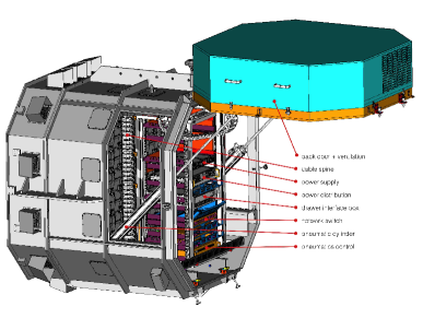
The back-end part of the camera consists of a so-called drawer interface box (DIB), a power supply unit, a power distribution box, an Ethernet switch and a pneumatics control unit (Fig. 1, right).
The DIB is the versatile heart of the new camera design. It combines several functionalities (see also Fig. 2):
-
•
Trigger interface to 60 drawers and to the array central trigger
-
•
Clock distribution to the drawers
-
•
Camera (L1) trigger generation
-
•
Interface to various camera components, see Fig. 2
-
•
Protection of PMT and camera electronics through a HV interlock and enable signal for the drawer power
-
•
GPS timestamping of events
With the technological advances of the past 20 years, the new back-end components could be designed and build in a much more compact way than in the original cameras. Instead of two racks, we now only needed one rack for all the units we built. There was even space to install a CTA auxiliary box in some of the cameras. It is an interface to test components (flat-fielding unit, timing unit) that were prototyped for the Cherenkov Telescope Array (CTA).
2.3 Mechanical upgrades
Besides the reworked electronics, several mechanical aspects were also improved. A new ventilation concept was worked out that steadily injects filtered and (optionally) heated air into the camera. It causes a steady overpressure in the entire camera body, and leads to a constant air flow through the drawers and all other small openings of the camera. This way a homogeneous cooling is achieved, and dust is kept out of the camera. The ventilation was integrated in a new rear door of the cameras (see Fig. 1, right).
This rear door is heavier than the previous ones, so a pneumatic solution was implemented to open and close them. Along with this effort, also the pneumatic system of the entire camera was reworked and modernised.
3 Network
Most of the components designed for this upgrade are built such that they also constitute a device in an internal Ethernet network of the camera. This is achieved with an FPGA (Cyclone IV) and an ARMv5-based Computer Module (Stamp9G45) in these devices. The two communicate through a fast 100MBit/s memory bus. This solution allows for high flexibility and good control and communication with all subsystems. It improves the overall resilience of the camera.
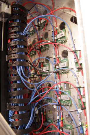
The trigger and data paths are realised using Cat. 6A and Cat. 6 Ethernet cables, respectively (see Fig. 4, right). The power is transmitted through industry standard 4-wire cables, ending with M8 connectors. The Ethernet and power cables are bundled in industrial cable spines, which were premounted in Europe and allowed for a fast cabling process on site.
Single devices all have copper-based Ethernet connections to a central switch, which is then connected to the main camera server by means of a optical fiber connection. As a novelty, the camera server is not located inside the camera as it was in the past, but in the computer “farm” (see Fig. 2), which eases its maintenance and prevents failures due to environmental factors.
4 Software
The presence of an ARM-based computer module running Linux on most of the camera systems makes communication between single components easy to establish. In order to reduce the software development time, several open source software solutions were adopted.
The operating system running on the Stamp9G45 is a version of Linux, build using the Yocto embedded Linux build system [5], with some kernel patches provided by the manufacturer. Slow control communication is implemented using Apache Thrift, a lightweight and performant RPC framework [6]. Data transfer was implemented using the ØMQ [7] smart socket message-passing library as a transport backbone. Raw event data messages are serialized via an optimized custom protocol, and monitoring data messages are serialized using the Google Protocol Buffers library [8]. A big advantage of the above RPC and serialization libraries is the automatic code generation they provide, which shortens the development cycles and is very stable against human programming errors.
The software in the various Linux systems of the camera is kept synchronised and up-to-date by installing one central instance of it on the camera server, and mounting it remotely in the file system of each device after start-up. This software also includes a test suite for each device that can be run any time as a self-check of basic functionality.
5 Summary and Outlook
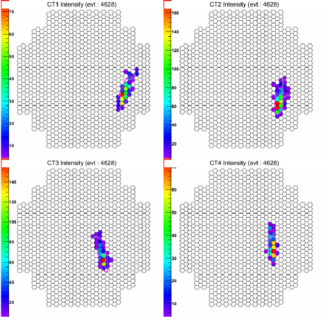
Four new and NECTAr-based Cherenkov cameras for the 12-meter telescopes of H.E.S.S. have been deployed in 2015/16, substantially reducing the dead time of the cameras and allowing for a more versatile and efficient operation and maintenance of the cameras. An example event recorded by the cameras is shown in Fig. 4, left.
Besides providing the experiment with a newer technology and a much reduced readout dead time, the new cameras allow for more sophisticated and flexible algorithms than previously to process the trigger and gamma-ray signals in the front-end part of the camera.
A second contribution to this conference reports on the performance of the new cameras presented here [3].
References
- [1] Aharonian, F., et al., “Observations of the Crab nebula with HESS”, A&A 457 899 (2006)
- [2] P. Vincent et al., “Performance of the H.E.S.S. cameras”, Proc. 28th ICRC (2003)
- [3] Bonnefoy, S., et al. “Performance of the upgraded H.E.S.S. cameras”, \posPoS(ICRC2017)805
- [4] Naumann, C. L. et al., “New electronics for the Cherenkov Telescope Array (NECTAr)”, NIM A 695, 44 (2012).
- [5] “Yocto project – Open Source embedded Linux build system, package metadata and SDK generator”, https://www.yoctoproject.org/, Accessed: 2016-05-28
- [6] “Apache Thrift - Home”, https://thrift.apache.org/, Accessed: 2016-05-28
- [7] “Code Connected - zeromq”, https://zeromq.org/, Accessed: 2016-05-28
- [8] “Protocol Buffers”, https://developers.google.com/protocol-buffers, Accessed: 2016-05-28