Hybridization-induced interface states in a topological-insulator–ferromagnetic-metal heterostructure
Abstract
Recent experiments demonstrating large spin-transfer torques in topological insulator (TI)-ferromagnetic metal (FM) bilayers have generated a great deal of excitement due to their potential applications in spintronics. The source of the observed spin-transfer torque, however, remains unclear. This is because the large charge transfer from the FM to TI layer would prevent the Dirac cone at the interface from being anywhere near the Fermi level to contribute to the observed spin-transfer torque. Moreover, there is yet little understanding of the impact on the Dirac cone at the interface from the metallic bands overlapping in energy and momentum, where strong hybridization could take place. Here, we build a simple microscopic model and perform first-principles-based simulations for such a TI-FM heterostructure, considering the strong hybridization and charge transfer effects. We find that the original Dirac cone is destroyed by the hybridization as expected. Instead, we find a new interface state which we dub ’descendent state’ to form near the Fermi level due to the strong hybridization with the FM states at the same momentum. Such a ‘descendent state’ carries a sizable weight of the original Dirac interface state, and thus inherits the localization at the interface and the same Rashba-type spin-momentum locking. We propose that the ‘descendent state’ may be an important source of the experimentally observed large spin-transfer torque in the TI-FM heterostructure.
I Introduction
Topological insulator (TI)-based heterostructures have become appealing candidates for spintronics due to the Dirac surface states
which exhibit the spin-momentum locking with opposite Rashba spin-windings at opposite surfacesHsieh et al. (2009). In particular, large spin-transfer torques comparable to conventional heavy-metal-based structures have been reported in three-dimensional (3D) TI-based bilayersMellnik et al. (2014); Fan et al. (2014); Wang et al. (2015).
Although large signals from the spin-momentum-locked Dirac surface states on the interface have been predicted in TI-ferromagnetic insulator heterostructuresMahfouzi et al. (2012), the materials involved in experiments are often ferromagnetic metals (FMs)Mellnik et al. (2014); Wang et al. (2015) since ferromagnetic insulators
are rare. Data analyses attributed the observed spin-transfer torques to an interface state with the same spin-winding as the Dirac surface state, when a pristine TI is in contact with a ferromagnetic layerMellnik et al. (2014); Fischer et al. (2016). The identity of this state, however, remains elusive.
This is because this Dirac surface state is very likely to be buried way below the raised chemical potential or even destroyed when hybridized with a large amount of FM states under an Ohmic contactZhang et al. (2016).
The effect of heterostructure formation on the primitive Dirac surface state localized at the interface (hence-forth referred to as the ‘Dirac interface state’) has been investigated for various materials. In the cases of TI-insulator bilayers, first-principles studies have found that interface states localized a bit deeper into the interface appear near the Fermi level with Dirac-like dispersion, while the original Dirac surface states are shifted way below due to band-bending potentials, which are induced by the mismatch between chemical potentials Lee et al. (2014); Men’shov et al. (2015); Govaerts et al. (2014); Park et al. (2013). As for TI-metal heterostructures, effective model studies have found Dirac interface states becoming diffusive under weak TI-metal couplingCulcer et al. (2010) while first-principles studies have reported no spin-momentum-locked interface states for various metalsSpataru and Léonard (2014); Zhang et al. (2016). In particular, severe hybridization is expected for cases where electrons in the Dirac interface states are coupled to many itinerant electrons with similar momenta and energies from a metal slab with much higher chemical potential. Such a scenario where itinerant electrons couple with a localized state has been generically described by the Fano-Anderson model to the lowest orderMahan (2000); Bergman and Refael (2010); Hsu et al. (2014). Fano coupling involving enough extended states can produce a new long-lived localized state sitting outside of the metal band which carries a substantial weight of the original localized stateMahan (2000). This ‘descendent state’ suggests the identity of the interface state with the same spin-winding as the Dirac interface state which leads to the large spin-transfer torque probed in the TI-FM heterostructure.
Our goal is to study the fate of the Dirac interface state in contact with an FM slab that has a much higher and many states overlapping with the Dirac interface state in energy and momentum. In this article, we take two complementary approaches: we construct a simple microscopic model and perform first-principles calculations, including the hybridization between the metal states and the Dirac cone in such a TI-FM bilayer. By examining spectroscopic properties, we identify the new interface state near as the descendent state, which is localized slightly deeper into the TI layer and inherits the spin texture of the original Dirac cone. The features obtained from the microscopic model agree with those from the first-principles-based simulations of the TI-FM bilayer. We propose that the descendent states may be an important source of the recently observed large spin-transfer torque in - heterostructureMellnik et al. (2014). The article is structured as follows: In Sec. II, we construct a lattice model for a TI-FM heterostructure with hybridization in the spirit of Fano-Anderson model. In Sec. III, we study the spectroscopic properties of the model and the properties of the newly formed interface states. In Secs. IV and V, we present a first-principles study on - bilayer using density functional theory (DFT) and compare the results to those from our lattice model. In Sec. VI, we summarize our results and address open questions.
II Lattice model for a TI-FM bilayer in the presence of hybridization
Generically the coupling between a localized state with energy and itinerant electrons with energy can be described by Fano modelMahan (2000) , where is the coupling strength. Bergman and Refael (2010) pointed out that can be used to model the lowest order interaction between a helical surface state and a metal bulk band, i.e. hybridization. As shown in Ref. Mahan, 2000 and Bergman and Refael, 2010, the hybridized spectral function of the surface state contains a broadened peak in the metallic band and two new delta functions with a reduced weight above and below the edges of the metallic band. The delta functions represent a part of the spectral weight associated with the original surface state that got pushed away from the metallic band through level repulsion as a result of coupling to extended states. These states form a new long-lived surface states albeit with smaller spectral weight. We thus dub the new surface states the ‘descendent states’ of the mother surface state. As the hybridization strength increases, the lifetime of the original surface state shortens while both the weights of the mother state carried by the descendent states and the gap to the metal band edges increase.
To examine the formation of descendent states in a TI-FM bilayer, we construct a tight-binding model capturing the coupling between the Dirac interface state with the extended states in the spirit of Fano model. The model for an -layer heterostructure reads with
| (1) |
where is the in-plane momentum, labels the layers stacked in the direction, and are Hamiltonians for a -layer TI slab and a -layer FM slab stacked in the direction.
is a four-band microscopic model describing a quintuple layer (QL) of pristine TIHsu et al. (2014) in the presence of a band-bending potential created by the mismatch between the Fermi levels of the TI and FM:
| (2) |
where , and are matrices in the basis of , , , and with / being spin and being orbitals of Bi/Se atoms. Here and contain tight-binding parameterization for pure Hsu et al. (2014); Zhang et al. (2009), while is the potential well which forms near the interface when the TI has a lower Fermi level than the FM. For simplicity, we assume the potential to be momentum -independent and has a spatial profile of based on the potential shapes in various TI-based bilayers obtained in ab initio calculationsSpataru and Léonard (2014); Park et al. (2013). The depth of the well is approximately the Fermi level-difference between the two materials. For our purpose of demonstrating the hybridization effect on the Dirac interface state, we choose the width to be small enough such that no additional quantum well state forms.
As for the FM slab, we model each layer by a simple two-band model
| (3) |
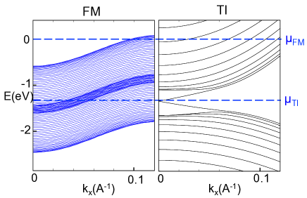
where and are matrices in spin basis. Here, is the dispersion given by in-plane hopping with in-plane lattice constant , is the Fermi level, is the hopping in the direction, and is the exchange energy where we choose the magnetization to be in the direction. The parameters of the FM layer are chosen such that the FM bands overlap with the Dirac interface branch in both momentum and energy [see Fig. 1(a)].
In the absence of hybridization, the bilayer Hamiltonian can be diagonalized into
| (4) |
where the four-spinors and annihilate the Dirac interface state with energy and the rest of the eigenstates in the TI with energy , respectively, and the two-spinor annihilates the FM states with energy . Here, and label the TI states besides the Dirac interface state and the FM states, respectively. In Fig. 1(a) we plot the spectra of the FM and TI layer before forming a heterostructure; the spectra are given by the dispersion of the model in Eq. (4) but with the band-bending potential . The effect of the band-bending potential is to break the degeneracy between the two TI surfaces and shifts the dispersion of the Dirac interface state downwards, which is expected when the localization length is smaller than the well width Men’shov et al. (2015).
Now we introduce the hybridization term which preserves in-plane momenta and spin:
| (5) |
where runs over all the FM states at . Here, we expect the strength to be proportional to the ‘spin-overlap’ between the FM states and the spin-momentum-locked Dirac interface state:
| (6) |
where and are ‘coarse-grained’ two-component ket spinors in spin basis for the FM and unhybridized Dirac interface states, respectively. Here we define , , runs over the TI (FM) layers, and labels the TI atomic orbitals. For simplicity, we assume to be identical for all FM states . To mimic our first-principle-calculated band structure later shown in Fig. 4(a), we further assume to increase with the momentum and take with . Finally, the full Hamiltonian including hybridization reads where
| (7) |
III The descendent state at the interface from the lattice model
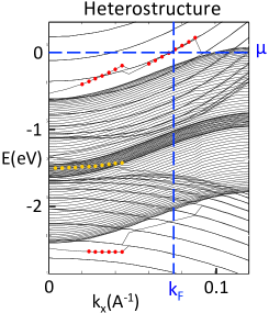
The dispersion of in Eq. (7) shows new interface states [red dots in Fig. 1(b)] formed above and below the FM bands as well as the “remnant states” [orange dots in Fig. 1(b)] which are residues of the Dirac interface states within the FM bands. Since the upper new interface branch emerges right above the upper band edge of FM, it is likely to intersect the Fermi level of the heterostructure, which is approximately given by that of the FM slab . We will thus focus only on this upper new interface branch for the rest of the article. To examine the properties of these states, we write the diagonalized full Hamiltonian at each as
| (8) |
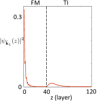
where annihilates the new interface state with energy above the FM upper band edge, and annihilate the rest of the eigenstates labeled by with energy . Here we define , . The spatial profile of the upper new interface state is then given by , which is a function of measured from the bottom of the FM slab along the finite dimension of the heterostructure. at the Fermi momentum [see Fig. 1(c)] shows that the TI portion of the upper new interface at the Fermi level localizes near the interface.
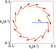
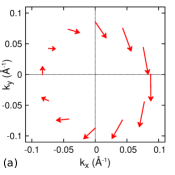
The new interface state at the Fermi level, i.e. the descendent state, also has a clockwise Rashba-type spin-winding just like the origianl Dirac interface state, as shown by the in-plane spin expectation values in Fig. 2(a). Here, where are the spin operators projected onto the TI side. The spin magnitude of states with negative is slightly smaller than that with positive due to the spin-dependence of hybridization strength in Eq. (6), which vanishes in the limit where the ferromagnetic exchange energy vanishes.
Finally, to determine the origin of this new interface state , we examine the weight of the original Dirac interface state carried by the heterostructure eigenstates and . Fig. 2(b) shows the spectral distribution of the weight and along the momentum-cut at where two peaks form outside of the FM band, which resembles that of the generic Fano modelMahan (2000). Specifically, the stronger peak is contributed by the new interface state on the Fermi level [see the red curve] while the weaker peak buried below the Fermi level and the residues within the band are contributed by the rest of the states [see the black curve]. Hence we have demonstrated that the hybridization-induced new interface state at the Fermi level is the descendent state of the original Dirac interface state, which thus inherits the wavefunction localization and spin texture of the mother state.
IV First-principles-based simulation of TI-FM bilayer
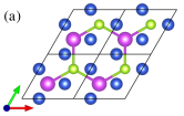
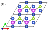
We simulate a TI-FM bilayer within DFT by using VASP Kresse and Joubert (1999). We use the generalized gradient approximation (GGA) Perdew et al. (1996) for the exchange-correlation functional and projector-augmented wave (PAW) pseudopotentials Blöchl (1994); Kresse and Joubert (1999). Spin-orbit coupling (SOC) is included self-consistently with the DFT calculation. We construct a TI-FM bilayer by using a supercell consisting of a 5-QL slab of Bi2Se3(111) beneath a Ni(111) slab of , where is 4 atomic layers, with a thick vacuum layer of 35.7 Å. The in-plane lattice constant of the supercell is fixed as the experimental lattice constant of the TI, 4.143 Å Nakajima (1963). This gives rise to a 4% compressive strain onto the Ni slab. We consider two different interface geometries shown in Fig. 3. The , , and coordinates of the QL nearest to the interface and the , , and coordinates of all the Ni atoms in the supercell are relaxed until the residual forces are lower than 0.1 eV/Å, while keeping the atomic coordinates of the rest of the QLs in the TI remain fixed. Interface (a) (considered in Ref. Zhang et al., 2016) gives a lower energy than interface (b) by 0.07 eV upon the relaxation. Therefore, henceforth, we present results obtained from interface (a). The distance between the TI and Ni layer is found to be 1.98 Å after the relaxation, which agrees with the previous DFT calculations of the TI-FM bilayer Spataru and Léonard (2014); Zhang et al. (2016). For the TI-FM bilayer, points are sampled in the geometry relaxation and calculations of electronic structure. The axis is along the [111] direction and the axis is along the [11] direction in the TI rhombohedral structure. In our simulation the magnetization of the Ni slab is in plane, such as parallel to the axis.
V The descendent state from the simulation
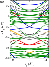
We calculate band structure of the TI-FM bilayer along different directions in the plane such as =0, , , , , , and , where is the azimuthal angle in the plane. The band structure along the axis is shown in Fig. 4(a). In the vicinity of the Dirac cone localized at the QL closest to the interface (topmost QL) is not found, although many bands from the Ni slab [green bands in Fig. 4(a)] appear. Our DFT+SOC calculations show some charge transfer from the Ni slab to the TI slab, which is caused by the difference between the chemical potentials of the TI and Ni slabs (the work functions of the TI and Ni slabs are 5.51 and 5.27 eV, respectively). This charge transfer shifts the Dirac surface states at the interface downward far below and causes very strong hybridization with the Ni states. In addition, the strong hybridization also induces significant relaxations in the coordinates of the topmost QL due to the Ni slab. These two factors make it difficult to discern the original Dirac interface state in the vicinity of , which is consistent with the result of the microscopic lattice model discussed in Sec. III.
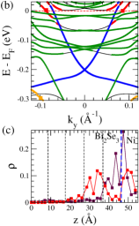
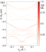
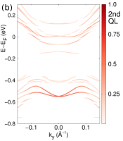
There are two classes of states near . One class of states [orange bands in Fig. 4(a)] are localized at the topmost QL [maroon curve in Fig. 4(c)] with energies in the range of eV somewhat away from the point (and in the vicinity of eV near the point). These states correspond to the “remnant states” found in the microscopic lattice model. The other more prominent class of states (red bands in Fig. 4(a) and (b)) are mostly localized into the topmost-1 QL [red curve in Fig. 4(c)]. These states resemble the descendent states of the lattice model in that (i) they appear near , (ii) they do not exhibit Dirac-like dispersion, and (iii) their wave function distribution is similar to that from the lattice model. Figure 5(a) and (b) show the same DFT-calculated band structure with the weight of the topmost QL and of the topmost-1 QL marked in color boxes, respectively.
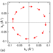
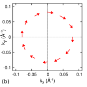
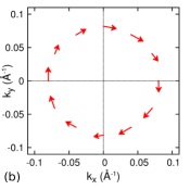
In addition, we examine the spin texture of the descendent state at by computing expectation values of the and components of spin, and at the aforementioned different values, within DFT. Figure 6(a) shows the DFT-calculated spin texture projected onto the TI layer, whereas Fig. 7(a) reveals the total spin texture including the contribution of the FM layer. As shown in Fig. 6(a), the DFT-calculated TI spin texture shows two main features: (i) spin-momentum locking; (ii) the magnitude of the spin polarization depending on in-plane momentum. The second feature is due to the in-plane magnetization of the Ni slab. Our DFT-calculated spin texture is comparable to that from the microscopic model [Fig. 2(a)], considering that the in-plane magnetization of the Ni side in the tight-binding model is along the axis. Now the DFT-calculated total spin texture of the descendent state, Fig. 7(a), also shares the similar main features to the projected spin texture with a much stronger dependence on in-plane momentum, due to the Ni magnetization. We find that the contribution of the Ni slab to the descendent state varies from 26% to 57% with the in-plane momentum, which leads to the in-plane momentum dependent coupling to the Ni slab.
We briefly discuss comparison of our DFT calculation to the previous DFT calculations of a TI-Ni bilayer Zhang et al. (2016); Spataru and Léonard (2014) and TI-Co bilayer Zhang et al. (2016); Marmolejo-Tejada et al. (2017). In these previous studies the spin-momentum locking we found above was either not reported Zhang et al. (2016); Spataru and Léonard (2014) or found well below Marmolejo-Tejada et al. (2017). There are four main differences between ours and the previous DFT calculations in addition to a different FM layer in Refs. Zhang et al., 2016; Marmolejo-Tejada et al., 2017: (i) different magnetization direction of the FM layer, (ii) different spatial localization of the state investigated for the spin-momentum locking, (iii) different TI layer thickness, and (iv) supercell geometry without vacuum vs slab geometry. Among the four differences, the second, third, and fourth are crucial factors. We propose that the descendent state (localized at topmost-1 QL) near contributes to the large enhancement of the spin-transfer torque in the TI-FM bilayer in experimentMellnik et al. (2014), while the previous studies were searching for the states localized at the topmost QL Zhang et al. (2016); Spataru and Léonard (2014); Marmolejo-Tejada et al. (2017). In Ref. Zhang et al., 2016, the TI layer considered, i.e. 3-QL of pristine Bi2Se3, is too thin to form a gapless TI Dirac cone, as experimentally confirmed Taskin et al. (2012); Kim et al. (2011); Zhang et al. (2010). Experimental data showed that a Bi2Se3 film has to be at least 5-QL thick to hold the gapless Dirac cone with a Berry phase. Furthermore, the supercell geometry without vacuum used in Ref. Zhang et al., 2016 induces charge transfer from both neighboring Ni layers to the ultra-thin TI layer. All of these would not favor the formation of the descendent states at the Fermi level, for the TI-FM layer considered in Ref. Zhang et al., 2016. A slab geometry with a vacuum layer is more relevant to the spin-transfer torque experimentMellnik et al. (2014) than a supercell geometry without vacuum. In our study, we take into account in-plane magnetization used in the spin-transfer torque experimentMellnik et al. (2014), whereas the latter studiesZhang et al. (2016); Spataru and Léonard (2014); Marmolejo-Tejada et al. (2017) considered out-of-plane magnetization due to different experimental set-ups from spin-transfer torque. In our DFT+SOC calculation, when the magnetization is out of plane, we find that the similar descendent state appears at with the similar wave function distribution in real space to that shown in Fig. 4(c), and that the descendent state has the spin-momentum locking as shown in Figs. 6(b) and 7(b).
VI Conclusion
We build a simple lattice model in the spirit of Fano-Anderson model and perform first-principles-based simulations in order to address the fate of the primitive Dirac interface state in TI-FM bilayers under large charge transfer and severe hybridization with many metallic states overlapping in momentum and energy. Both the tight-binding model and simulations showed that while destroying the Dirac interface state, a large enough hybridization could also create a new descendent state near the Fermi level which inherits both the spatial localization on the interface and the Rashba-type spin-momentum locking. Our findings suggest this hybridization-induced descendent state to be a possible candidate for the source that contributes to the experimentally observed large spin-transfer torque in TI-FM bilayers. While the spin-transfer torque in TI-based structures has attracted growing theoretical attentionFischer et al. (2016); Ndiaye et al. (2017); Kim et al. (2017), our model provides a starting point for theoretical studies on TI-FM heterostructures to take into account the lowest order effects from the FM layer. While the hybridization strength is material-dependent, our simple model provides a generic way to describe the hybridization effect for the experimentally relevant cases in which the Dirac interface state overlaps with many FM states.
Acknowledgements Y-TH was supported by the Cornell Center for Materials Research with funding from the NSF MRSEC program (DMR-1719875) and in part by Laboratory for Physical Sciences and Microsoft. E-AK was supported by U.S. Department of Energy, Office of Basic Energy Sciences, Division of Materials Science and Engineering under Award DE-SC0010313. E.-A.K. acknowledges Simons Fellow in Theoretical Physics Award #392182 and thanks the hospitality of KITP supported by Grant No. NSF PHY11- 25915. K.P. was supported by the U.S. National Science Foundation Grant No. DMR-1206354. The computational support was provided by SDSC under DMR060009N and VT ARC computer clusters.
References
- Hsieh et al. (2009) D. Hsieh, Y. Xia, D. Qian, L. Wray, J. H. Dil, F. Meier, J. Osterwalder, L. Patthey, J. G. Checkelsky, N. P. Ong, A. V. Fedorov, H. Lin, A. Bansil, D. Grauer, Y. S. Hor, R. J. Cava, and M. Z. Hasan, Nature 460, 1101 (2009).
- Mellnik et al. (2014) A. R. Mellnik, J. S. Lee, A. Richardella, J. L. Grab, P. J. Mintun, M. H. Fischer, A. Vaezi, A. Manchon, E.-A. Kim, N. Samarth, and D. C. Ralph, Nature 511, 449 (2014).
- Fan et al. (2014) Y. Fan, P. Upadhyaya, X. Kou, M. Lang, S. Takei, Z. Wang, J. Tang, L. He, L.-T. Chang, M. Montazeri, G. Yu, W. Jiang, T. Nie, R. N. Schwartz, Y. Tserkovnyak, and K. L. Wang, Nat Mater 13, 699 (2014).
- Wang et al. (2015) Y. Wang, P. Deorani, K. Banerjee, N. Koirala, M. Brahlek, S. Oh, and H. Yang, Phys. Rev. Lett. 114, 257202 (2015).
- Mahfouzi et al. (2012) F. Mahfouzi, N. Nagaosa, and B. K. Nikolić, Phys. Rev. Lett. 109, 166602 (2012).
- Fischer et al. (2016) M. H. Fischer, A. Vaezi, A. Manchon, and E.-A. Kim, Phys. Rev. B 93, 125303 (2016).
- Zhang et al. (2016) J. Zhang, J. P. Velev, X. Dang, and E. Y. Tsymbal, Phys. Rev. B 94, 014435 (2016).
- Lee et al. (2014) A. T. Lee, M. J. Han, and K. Park, Phys. Rev. B 90, 155103 (2014).
- Men’shov et al. (2015) V. N. Men’shov, V. V. Tugushev, S. V. Eremeev, P. M. Echenique, and E. V. Chulkov, Phys. Rev. B 91, 075307 (2015).
- Govaerts et al. (2014) K. Govaerts, K. Park, C. De Beule, B. Partoens, and D. Lamoen, Phys. Rev. B 90, 155124 (2014).
- Park et al. (2013) K. Park, C. D. Beule, and B. Partoens, New Journal of Physics 15, 113031 (2013).
- Culcer et al. (2010) D. Culcer, E. H. Hwang, T. D. Stanescu, and S. Das Sarma, Phys. Rev. B 82, 155457 (2010).
- Spataru and Léonard (2014) C. D. Spataru and F. m. c. Léonard, Phys. Rev. B 90, 085115 (2014).
- Mahan (2000) G. D. Mahan, Many-Particle Physics, 3rd ed. (Plenum, New York, N.Y., 2000).
- Bergman and Refael (2010) D. L. Bergman and G. Refael, Phys. Rev. B 82, 195417 (2010).
- Hsu et al. (2014) Y.-T. Hsu, M. H. Fischer, T. L. Hughes, K. Park, and E.-A. Kim, Phys. Rev. B 89, 205438 (2014).
- Zhang et al. (2009) H. Zhang, C.-X. Liu, X.-L. Qi, X. Dai, Z. Fang, and S.-C. Zhang, Nat Phys 5, 438 (2009).
- Kresse and Joubert (1999) G. Kresse and D. Joubert, Phys. Rev. B 59, 1758 (1999).
- Perdew et al. (1996) J. P. Perdew, K. Burke, and M. Ernzerhof, Phys. Rev. Lett. 77, 3865 (1996).
- Blöchl (1994) P. E. Blöchl, Phys. Rev. B 50, 17953 (1994).
- Nakajima (1963) S. Nakajima, J. Phys. Chem. Sol. 24, 479 (1963).
- Marmolejo-Tejada et al. (2017) J. M. Marmolejo-Tejada, K. Dolui, P. Lazić, P.-H. Chang, S. Smidstrup, D. Stradi, K. Stokbro, and B. K. Nikolić, Nano Letters 17, 5626 (2017), pMID: 28795576, http://dx.doi.org/10.1021/acs.nanolett.7b02511 .
- Taskin et al. (2012) A. A. Taskin, S. Sasaki, K. Segawa, and Y. Ando, Phys. Rev. Lett. 109, 066803 (2012).
- Kim et al. (2011) Y. S. Kim, M. Brahlek, N. Bansal, E. Edrey, G. A. Kapilevich, K. Iida, M. Tanimura, Y. Horibe, S.-W. Cheong, and S. Oh, Phys. Rev. B 84, 073109 (2011).
- Zhang et al. (2010) Y. Zhang, K. He, C.-Z. Chang, C.-L. Song, L.-L. Wang, X. Chen, J.-F. Jia, Z. Fang, X. Dai, W.-Y. Shan, S.-Q. Shen, Q. Niu, X.-L. Qi, S.-C. Zhang, X.-C. Ma, and Q.-K. Xue, Nature Physics 6, 584 (2010).
- Ndiaye et al. (2017) P. B. Ndiaye, C. A. Akosa, M. H. Fischer, A. Vaezi, E.-A. Kim, and A. Manchon, Phys. Rev. B 96, 014408 (2017).
- Kim et al. (2017) K.-W. Kim, K.-J. Lee, J. Sinova, H.-W. Lee, and M. D. Stiles, Phys. Rev. B 96, 104438 (2017).