Ion acceleration with an ultra-intense two-frequency laser tweezer
Abstract
Ultra-intense lasers produce and manipulate plasmas, allowing to locally generate extremely high static and electromagnetic fields. This Letter presents a concept of an ultra-intense optical tweezer, where two counter-propagating circularly polarized intense lasers of different frequencies collide on a nano-foil. Interfering inside the foil, lasers produce a beat wave, which traps and moves plasma electrons as a thin sheet with an optically controlled velocity. The electron displacement creates a plasma micro-capacitor with an extremely strong electrostatic field, that efficiently generates narrow-energy-spread ion beams from the multi-species targets, e.g. protons from the hydrocarbon foils. The proposed ion accelerator concept is explored theoretically and demonstrated numerically with the multi-dimensional particle-in-cell simulations.
While low-intensity laser tweezers and lattices manipulate microscopic objects Ashkin et al. (1986); Chu (1991); Grier (2003), lasers with higher intensities ionize matter and exert a force on the released plasma Mourou et al. (2006). In the subcritical density plasmas, where electron plasma frequency is smaller than that of the laser , laser beams can propagate and drive wakefields, which is actively used now for electron acceleration Rosenbluth and Liu (1972); Tajima and Dawson (1979). For the relativistically intense lasers, , electron plasma frequency is reduced by the Lorentz factor, , allowing light to penetrate even solid, overcritical plasma densities Akhiezer and Polovin (1956). Such interaction occurs in the process of laser acceleration of ions, where laser heats a solid target to generate plasma with a strong charge separation Daido et al. (2012); Macchi et al. (2013). Here we have used , and to denote the electron charge, rest mass and classical radius, , and stand for the density and effective Lorentz factor of electron plasma, and is the speed of light.
Modern high power lasers and advanced targetry provide a number of laser ion acceleration methods including acceleration via shealth fields Snavely et al. (2000), radiation pressure Esirkepov et al. (2004); Macchi et al. (2005), collisionless shock Silva et al. (2004); Haberberger et al. (2012); Fiuza et al. (2012), magnetic vortices Bulanov et al. (2005, 2010); Nakamura et al. (2010) etc. In most of the existing schemes, the charge-separation fields are produced by thermal electrons heated by intense lasers, that accelerate ions from solid targets, delivering an ion flux with a complex and typically broad spectrum of different species. The radiation pressure schemes, in particular the so-called light sail (LS) acceleration, take another path – laser pushes an ultra-thin foil and accelerates all particles at the same rate, and thus is capable of generating quasi-monoenergetic beams Esirkepov et al. (2004); Klimo et al. (2008); Robinson et al. (2008); Yan et al. (2008); Macchi et al. (2009). In LS, the laser plasma heating is minimized. However, target becomes susceptible to the destructive plasma instability Pegoraro and Bulanov (2007); Klimo et al. (2008), which was shown recently to be related to the coupling between electron oscillations and ion plasma modes Wan et al. (2016, 2018). In this Letter we present a new acceleration concept, where two ultra-intense laser beams are used to spatially separate the electron and ion species thereby acting as a relativistically intense optical tweezer. In this approach, plasma instability is fully mitigated, and high gradient acceleration is produced by the optically controlled charge-separation, which provides high quality of accelerated ions.
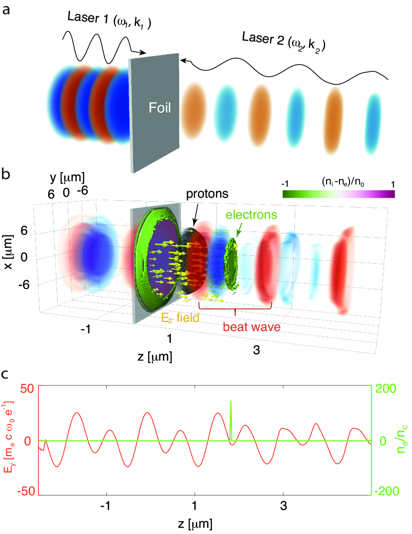
The proposed optical scheme relies on two circularly polarized (CP) lasers of different frequencies colliding on a single nano-foil (see Fig.1). In order for the lasers to interfere inside the target, its thickness needs to be smaller than the relativistic skin depth of electron plasma, . Once lasers collide on the target, their fields sum up into a beat wave, and its propagation direction and velocity are controlled by the ratio of the laser frequencies. Electrons of the foil first get squeezed into a thin sheet by the radiation pressure, and then are dragged by the beat wave, as if grabbed by a pair of tweezers. This creates a nearly constant longitudinal electric field between the electron sheet and the slow ion core (see Fig. 1b and c). If the target contains an admixure of light and heavy ions, then the light ions (e.g. protons) are quickly accelerated by this static field, and gain high energies on a distance of few micrometers.
This relativistic tweezer scheme has been demonstrated based on a three-dimensional particle-in-cell (PIC) simulation using code OSIRIS Fonseca et al. (2002), where two counter-propagating ten-cycle, temporally flat-top CP laser pulses with wavelengths m and , and are focused to 8 m spots on a 20 nm hydrocarbon foil. The pre-ionized uniform plasma foil has electron density , proton density , and C+6 ion density , where cm-3 is the critical plasma density for 800 nm laser wavelength. Initial electron temperature is set to 1 keV. To resolve kinetics of the high density plasma, we use numerical grid with the longitudinal cell size nm and the transverse ones nm. To ensure low particle noise, 32 macro-particles per species per cell are used. The output of this simulation is presented in Figure 1.
Let us first consider the dynamics of an electron in the electromagnetic wave created by two lasers with the frequencies , wavenumbers , and the same amplitudes . The field of interfering lasers has a phase component, , which travels at a sub-luminal velocity , in the direction of the higher frequency laser. In a frame co-propagating with this beat-wave, both lasers have the same frequencies and wavenumbers , and the total on-axis laser field can be written as,
| (1) |
where and are the transverse unit vectors. Considering that initially electron is at rest, its longitudinal motion follows the equation,
where two terms in the right-hand side are the ponderomotive force of the standing wave , and the averaged Coulomb force from the charge-separation . Here, is the initial target thickness, and is the charge-separation field (shown with arrows in Fig. 1b). To estimate the ratio between these forces, we first assume a minimal laser amplitude to be defined by the relativistic transparency condition Vshivkov et al. (1998), , where we have added a fitting factor of 2 estimated from the simulations. We also assume the effective electron Lorentz factor , from which one can show that the charge-separation force is actually small compared to the maximum of ponderomotive force, . Therefore, neglecting , and for the initial electron velocity in the moving frame , we can estimate that electron is trapped, if . For the ultra-intense lasers, , this allows electron trapping even for the nearly luminal tweezer velocities, . In the present simulation, .
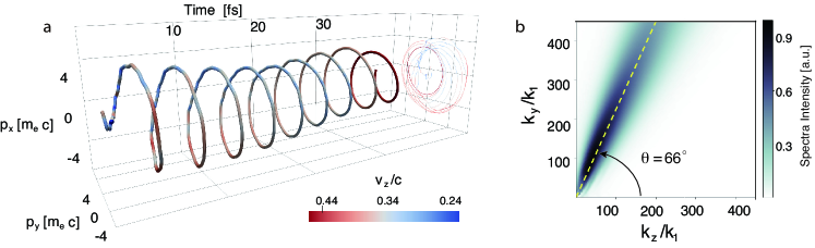
Once trapped, electron sheet moves helically in the laser field and travels with the beat-wave in a phase determined by both, laser ponderomotive force and static field of the ion plasma. Their averaged phase orbit is shown in Fig. 2a. Since the transverse oscillations are relativistically strong, the electrons produce a broadband synchrotron light Sokolov and Ternov (1968), which in this case is emitted into a ring-like shape at the angle to the tweezer propagation direction. In Fig. 2b we show the numerically reconstructed spectral-angular radiation distribution, where the emission angle is close to theoretical estimate . The critical photon energy keV, and total radiated energy reaches a few micro-Joules level (for the trapped charge nC).
For the considered interaction parameters, the charge separation field between electron sheet and ion plasma reaches 60 TV/m, and accelerates protons on a time scale, when the heavier carbon ions are essentially immobile (see Fig.1b). This acceleration is nearly uniform, and it continues until protons outrun the electron sheet. The maximum acceleration time can be estimated as
| (2) |
where is the acceleration rate of protons, is the proton rest mass, and is the Lorentz factor of the moving frame. Integrating the accelerated motion one can get the maximum energy gain of protons,
| (3) |
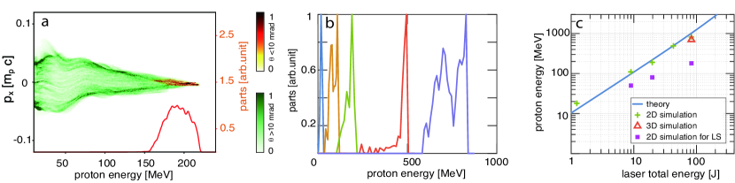
In the simulation presented in Fig.1, acceleration process lasts for about 40 fs, and protons gain maximum energy of 220 MeV. These values are in good agreement with the theoretical estimates of 36 fs and 230 MeV from Eqs. (2) and (3) respectively. In Fig. 3, we show the proton phase space at the moment when they outrun the electrons. One can see a quasi-monoenergetic group of protons with a FWHM energy spread around 20% formed within a small divergence angle mrad (orange colormap and curve). This group contains particles, and it may indeed be of interest for the radiotherapy applications Bulanov et al. (2002); Malka et al. (2004). Meanwhile, about protons with the broadband spectrum and larger divergence, mrad, (green in Fig. 3a) originate from the borders of irradiated region, where the accelerating field becomes three dimensional (position dependent).
We note, that the above analysis assumes the flat-top laser temporal profiles. It is important to verify how the discussed mechanisms are affected by the finite laser shapes, and for this we have run a series of additional 2D PIC simulations. These simulations show, that for beams with Gaussian temporal envelopes the tweezer effect is very similar to the idealized case, and production of 200 MeV protons in this case required slightly higher field amplitudes, . The finite transverse profiles of laser beams also have an important effect on the scheme. Since the extracted electron sheet has a finite size, lasers can diffract at its edges, and this diffraction erodes the edges of the electron sheet, thus decreasing its size with propagation. From the simulations we have found that the time of the sheet destruction depends on the lasers radii as .
From these considerations, we can now estimate how the maximum proton energy scales with the input laser energy. Erosion time of the electrons from the sheet edge defines the required laser durations as, , and their energies scale as, . Assuming that the optimal acceleration is reached, when is close to the 1D maximum acceleration time (Eq. 2), one can find the scaling as:
| (4) |
where the total laser energy is in Joules, and and are in the same units. We note that the value of is determined by the relation of , and varies for different proton energy (see Eq. 3).
We have tracked this dependency in a series of 2D PIC simulations, by considering only the collimated protons, in mrad (see Fig. 3b). In these simulations, both lasers have Gaussian temporal and super-Gaussian transverse profiles, and target ion composition is the same as in the above 3D case. The values of m and m and nm are fixed, while other parameters were chosen in a way described previously in order to maintain the optimal acceleration conditions.
As shown in Fig. 3b and 3c, protons with energy spreads and energies from 20 MeV to 830 MeV are obtained for 1 J to 80 J of laser energies. This agrees well with the dependency given by Eq. (4). Assuming a cylindrical symmetry we estimate the corresponding quantities of the physical protons in these simulations as . In Fig. 3c, the added 3D simulation also shows similar proton final energy. Besides, we have compared this tweezer approach with the “light sail” scheme for the same laser energy and optimal acceleration parameters Yan et al. (2008); Macchi et al. (2009). The result shows, that the present scheme can provide 2-5 times higher energy gain than the “light sail” acceleration. By adding time jitters between laser pulses or imbalancing their amplitudes in the simulations, we have found that the acceptable jitter limit is about 10 femtoseconds, and the normalized laser amplitudes should not deviate from each other more than, .
In conclusion, we have proposed a high-intensity laser tweezer based on two relativistically intense lasers of different frequencies colliding on a nano-foil. The moving beat pattern of the lasers acts as a tweezer that drags the plasma electrons out of the ionized foil. The resultant capacitor-like field readily accelerates protons from the hydrocarbon plasma. The scheme is free of electron-ion coupling instability and is based on a simple nano-foil. This makes the proposed approach simpler to realize in practice compared to another recently proposed scheme that employs a standing wave incident on multi-nano-layers with an accurate phase control of a chirped laser Mackenroth et al. (2016). The process is also accompanied by a strong synchrotron-like emission in the sub soft x-ray region, which can be used as a direct diagnostics of the interaction parameters, e.g. the tweezer phase velocity. Production of the two color laser pair, can be potentially achieved used through second-harmonic generation Bargsten et al. (2017) or OPCPA techniquesCerullo and De Silvestri (2003); Mikhailova et al. (2011). We anticipate this concept to open the path for the next generation of the compact laser-based high quality proton accelerators, and a wide range of their applications.
This work was supported by NSFC Grant No. 11425521, No. 11535006, No. 11475101 and No. 11775125, the Thousand Young Talents Program, and DOE grant DE-SC0010064. Simulations were performed on Sunway TaihuLight cluster at National Supercomputing Center and Edison cluster at NERSC. This wok has benefited from Gerry Schwartz and Heather Reisman, Israel Science Foundation, and VATAT supports.
References
- Ashkin et al. (1986) A. Ashkin, J. M. Dziedzic, J. E. Bjorkholm, and S. Chu, Optics Letters. 11, 288 (1986).
- Chu (1991) S. Chu, Science 253, 861 (1991).
- Grier (2003) D. G. Grier, Nature 424, 810 (2003).
- Mourou et al. (2006) G. A. Mourou, T. Tajima, and S. V. Bulanov, Reviews of Modern Physics 78, 309 (2006).
- Rosenbluth and Liu (1972) M. N. Rosenbluth and C. S. Liu, Physical Review Letters 29, 701 (1972).
- Tajima and Dawson (1979) T. Tajima and J. M. Dawson, Physical Review Letters 43, 267 (1979).
- Akhiezer and Polovin (1956) A. I. Akhiezer and R. V. Polovin, Soviet Phys. JETP 3, 696 (1956).
- Daido et al. (2012) H. Daido, M. Nishiuchi, and A. S. Pirozhkov, Reports on Progress in Physics 75, 056401 (2012).
- Macchi et al. (2013) A. Macchi, M. Borghesi, and M. Passoni, Reviews of Modern Physics 85, 751 (2013).
- Snavely et al. (2000) R. A. Snavely, M. H. Key, S. P. Hatchett, T. E. Cowan, M. Roth, T. W. Phillips, M. A. Stoyer, E. A. Henry, T. C. Sangster, M. S. Singh, S. C. Wilks, A. MacKinnon, A. Offenberger, D. M. Pennington, K. Yasuike, A. B. Langdon, B. F. Lasinski, J. Johnson, M. D. Perry, and E. M. Campbell, Physical Review Letters 85, 2945 (2000).
- Esirkepov et al. (2004) T. Esirkepov, M. Borghesi, S. Bulanov, G. Mourou, and T. Tajima, Physical Review Letters 92, 175003 (2004).
- Macchi et al. (2005) A. Macchi, F. Cattani, T. V. Liseykina, and F. Cornolti, Physical Review Letters 94, 165003 (2005).
- Silva et al. (2004) L. O. Silva, M. Marti, J. R. Davies, R. A. Fonseca, C. Ren, F. S. Tsung, and W. B. Mori, Physical Review Letters 92, 015002 (2004).
- Haberberger et al. (2012) D. Haberberger, S. Tochitsky, F. Fiuza, C. Gong, R. A. Fonseca, L. O. Silva, W. B. Mori, and C. Joshi, Nature Physics 8, 95 (2012).
- Fiuza et al. (2012) F. Fiuza, A. Stockem, E. Boella, R. A. Fonseca, L. O. Silva, D. Haberberger, S. Tochitsky, C. Gong, W. B. Mori, and C. Joshi, Physical Review Letters 109, 215001 (2012).
- Bulanov et al. (2005) S. V. Bulanov, D. V. Dylov, T. Z. Esirkepov, F. F. Kamenets, and D. V. Sokolov, Plasma Physics Reports 31, 369 (2005).
- Bulanov et al. (2010) S. S. Bulanov, V. Y. Bychenkov, V. Chvykov, G. Kalinchenko, D. W. Litzenberg, T. Matsuoka, A. G. R. Thomas, L. Willingale, V. Yanovsky, K. Krushelnick, and A. Maksimchuk, Physics of Plasmas 17, 043105 (2010).
- Nakamura et al. (2010) T. Nakamura, S. V. Bulanov, T. Z. Esirkepov, and M. Kando, Physical Review Letters 105, 135002 (2010).
- Klimo et al. (2008) O. Klimo, J. Psikal, J. Limpouch, and V. T. Tikhonchuk, Phys. Rev. ST Accel. Beams 11, 031301 (2008).
- Robinson et al. (2008) A. P. L. Robinson, M. Zepf, S. Kar, R. G. Evans, and C. Bellei, New J. Phys. 10, 013021 (2008).
- Yan et al. (2008) X. Q. Yan et al., Physical Review Letters 100, 135003 (2008).
- Macchi et al. (2009) A. Macchi, S. Veghini, and F. Pegoraro, Physical Review Letters 103, 085003 (2009).
- Pegoraro and Bulanov (2007) F. Pegoraro and S. V. Bulanov, Physical Review Letters 99, 065002 (2007).
- Wan et al. (2016) Y. Wan et al., Physical Review Letters 117, 234801 (2016).
- Wan et al. (2018) Y. Wan, C.-H. Pai, C. Zhang, F. Li, Y. Wu, J. Hua, W. Lu, C. Joshi, W. Mori, and V. Malka, Physical Review E 98, 013202 (2018).
- Fonseca et al. (2002) R. A. Fonseca et al. (Springer-Verlag Berlin, 2002) pp. 342–351.
- Vshivkov et al. (1998) V. A. Vshivkov, N. M. Naumova, F. Pegoraro, and S. Bulanov, Physics of Plasmas 5, 2727 (1998).
- Sokolov and Ternov (1968) A. Sokolov and I. Ternov, Synchrotron Radiation (Pergamon Press, 1968).
- Bulanov et al. (2002) S. V. Bulanov, T. Z. Esirkepov, V. S. Khoroshkov, A. V. Kunetsov, and F. Pegoraro, Physical Review A 299, 240 (2002).
- Malka et al. (2004) V. Malka et al., Medical Physics 31, 1587 (2004).
- Mackenroth et al. (2016) F. Mackenroth, A. Gonoskov, and M. Marklund, Physical Review Letters 117, 104801 (2016).
- Bargsten et al. (2017) C. Bargsten, R. Hollinger, M. G. Capeluto, V. Kaymak, A. Pukhov, S. Wang, A. Rockwood, Y. Wang, D. Keiss, R. Tommasini, et al., Science Advances 3, e1601558 (2017).
- Cerullo and De Silvestri (2003) G. Cerullo and S. De Silvestri, Review of Scientific Instruments 74, 1 (2003).
- Mikhailova et al. (2011) J. M. Mikhailova, A. Buck, A. Borot, K. Schmid, C. Sears, G. D. Tsakiris, F. Krausz, and L. Veisz, Optics Letters 36, 3145 (2011).