email: johann.zemella@desy.de
]Deutsches Elektron Synchrotron, 22603 Hamburg, Germany
]Deparment of Engineering Physics, Tsinghua University, Beijing 100084, China
Measurements of wake-induced electron beam deflection
in a dechirper at the Linac Coherent Light Source
Abstract
The RadiaBeam/SLAC dechirper, a structure consisting of pairs of flat, metallic, corrugated plates, has been installed just upstream of the undulators in the Linac Coherent Light Source (LCLS). As a dechirper, with the beam passing between the plates on axis, longitudinal wakefields are induced that can remove unwanted energy chirp in the beam. However, with the beam passing off axis, strong transverse wakes are also induced. This mode of operation has already been used for the production of intense, multi-color photon beams using the Fresh-Slice technique, and is being used to develop a diagnostic for attosecond bunch length measurements. Here we measure, as function of offset, the strength of the transverse wakefields that are excited between the two plates, and also for the case of the beam passing near to a single plate. We compare with analytical formulas from the literature, and find good agreement. This report presents the first systematic measurements of the transverse wake strength in a dechirper, one that has been excited by a bunch with the short pulse duration and high energy found in an X-ray free electron laser.
I Introduction
The Linac Coherent Light Source (LCLS) Emma et al. (2010) is a user facility at SLAC National Accelerator Laboratory generating femto-second-long X-ray photon pulses. The precise control of the electron beam parameters is essential for the optimal performance of the free electron laser (FEL) Krinsky and Huang (2003); Saldin et al. (2006).
In order to generate X-ray FEL pulses, high slice electron density, low slice emittance, and low slice energy spread are needed Dohlus et al. (2008). At the LCLS the high current is achieved via a staged magnetic compression scheme. Normally, however, an uncorrected longitudinal position to energy correlation—an energy chirp—remains after the bunch has left the final compressor chicane. An idea was developed of using a metallic structure with small corrugations for chirp control in X-ray FELs Bane and Stupakov (2012). When placed after the linac, such a “dechirper”, through wakefields induced by the beam, can passively remove unwanted energy chirp before the beam enters the undulator. One such device, the RadiaBeam/SLAC dechirper, was installed in the LCLS at the end of 2015. It consists of two modules, each comprising two, flat adjustable corrugated plates with the beam passing in between.
In addition to the longitudinal wake effect in the dechirper, the induced transverse wake effects are strong and cannot be ignored. If the beam moves through the device off axis, a strong transverse kick is induced that is largest at the tail of the bunch; but even if the beam passes through the structure on axis, strong induced quadrupole wakes can greatly increase the beam’s projected emittance. Nevertheless, recently there has been success in taking advantage of the strong transverse wake forces. Dechirper transverse wakefields were used to selectively control the electron bunch lasing slice at the LCLS, allowing for the production of intense, multi-color photon beams using the Fresh-Slice technique Lutman et al. (2016). A similar idea is being investigated, one that has the beam on axis and uses the quad wake to select the lasing slice Qin et al. (2017). Also, temporal diagnostic schemes based on the transverse wakes have been demonstrated at low energies Bettoni et al. (2016), and hold the promise of an attosecond electron bunch diagnostic operating at high energies Novokhatski (2015).
The measurement of the wakefields—both longitudinal and transverse—of a flat plate dechirper was performed before Emma et al. (2014); however, the beam energy and current were low: MeV and A, respectively. The same can be said for detailed measurements of the quad wake of a dechirper Lu et al. (2016). In contrast, the measurements presented here have the energies ( GeV) and currents (several kA’s) of a functioning X-ray FEL. Since the bunch is much shorter, we probe the impedance to much higher frequencies than has been done before. Note that some of the results presented here, as well as additional aspects of the measurements, can be also found in Ref. Guetg et al. (2016).
In this report, we present measurements of the deflection of an electron bunch: (1) as it passes off axis between two plates of the RadiaBeam/LCLS dechirper, as a function of offset, and (2) as it passes near a single plate of the dechirper, as a function of beam offset. We will compare the measurements with analytical formulas derived in Ref. Bane et al. (2016a). Note that these formulas were confirmed to agree well with numerical simulations (for the typical LCLS bunch lengths) using the computer program Echo(2D) Zagorodnov et al. (2015). In the present work we also report on measurements of the transverse kick experienced by a beam passing close to a single dechirper plate. These results are compared with wake formulas found in Bane et al. (2016b).
This report is organized as follows. In Sec. II we present the analytical wake formulas that are used to compare to the measurements. In Sec. III the experimental setup is described. In Sec. IV we present two-plate measurement results and compare to theory, and in Sec. V we do the same for the single plate measurements. The conclusions come in Sec. VI. In Appendix A we derive the average kick for a uniform bunch from the wakefield formulas, and also present longitudinal results needed for the single plate comparisons.
II Theory of wakefield-induced electron deflection
The concept of wakefield is useful for the study of beam dynamics of high energy, charged-particle beams in an accelerator. Leading charged particles generate an electromagnetic field (wakefield) that interacts with the boundary and then acts on trailing particles. For a high energy beam passing through a device, like a dechirper, the effect can be described by an impulse kick on each particle. For a line charge beam moving at offset parallel to the axis of such a structure, the kick induced at longitudinal position (within the bunch) by a transverse wakefield is described by the convolution
| (1) |
with the bunch charge, the length of structure, the transverse, point charge wakefield (in units of V/pC per unit length), and the longitudinal bunch distribution (normalized to unit area). Here the head of the bunch is located in the negative direction, with .
II.1 Wakes for a pencil beam in flat geometry
Our measurements concern “pencil beams,” i.e. beams with a transverse extent that is small compared to the aperture or distance to the nearest wall. Consider a vacuum chamber object that has flat geometry, oriented as the two plates of the horizontal dechirper used in the measurements of this report (the plates are parallel to the plane, which defines the symmetry axis). For small offsets from the axis, the transverse point charge wake can be written in the form Bane and Stupakov (2015)
| (2) |
with (, ), (,), respectively the offset of the leading and trailing particle; with , , respectively the dipole and quadrupole wake functions (the over-bars indicate that these functions are normalized to offset and thus have different units than ). For the case of two particles still near each other transversally but away from the axis, with the leading particle at offset and the trailing one at (with small compared to the the distance to the nearest wall) , the wakes are of the form Bane et al. (2016a)
| (3) |
In this case, both the dipole and quad wake components depend non-linearly on the offset . For the case of a beam near a single plate at offset , the form of the wakes is the same but with the parameter replaced by .
The transverse wakes at the origin in (at ) start with a linear slope. In a two-plate dechirper of gap , for a beam near the axis, the slopes at the origin of the dipole and quad wake functions are given by (see e.g. Bane and Stupakov (2015))
| (4) |
with and the speed of light. For a pencil beam passing by a single dechirper plate, the slopes of the transverse wakes at are given as Bane et al. (2016b)
| (5) |
II.2 Analytical formulas for short bunches
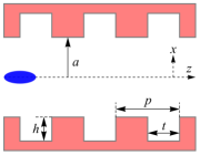
The dechirper geometry is sketched in Fig. 1. The parameters are half gap and corrugation parameters: period , longitudinal gap , and depth . Ideally, the corrugation parameters of a dechirper are small (, ), but with Bane and Stupakov (2012). The equations described below apply for the type of parameters of the RadiaBeam/SLAC dechirper and the short bunches at the end of the LCLS. They are the equations for a horizontal dechirper, i.e. one with plates parallel to the plane, like the one shown in the figure.
The transverse point charge wake, both for the cases of the beam at offset between two plates and the beam at distance from a single plate, is given in the form Bane et al. (2016a)
| (6) |
with and constants that depend on the aperture, the beam offset, and the corrugation parameters. Here the leading and trailing particles are taken to have identical transverse offsets; thus equals the first, dipole term of Eq. 3. For two plates separated by distance , with the beam offset from the axis by , the constants are (subscript stands for “double” plates)
| (7) |
the scale factor
| (8) |
where .
In the case of a beam passing by a single plate at distance , the constants are given by (subscript stands for “single” plate) Bane et al. (2016b)
| (9) |
When the beam passes the dechirper off axis, it receives a transverse wake kick, which translates to a change in offset at a downstream beam position monitor (BPM). In the experiments described below we record the change in offset at such a BPM, which actually measures the offset change averaged over the longitudinal bunch distribution. Since, in our case, there is only a drift region between dechirper and measuring BPM, the change in (averaged) offset is simply given as
| (10) |
with the charge of an electron, the length of the dechirper plate, the distance from dechirper to the measuring BPM, the kick factor (the average of the transverse bunch wake), and the bunch energy. The bunch at the end of the LCLS is short and, to good approximation, has a uniform bunch distribution. The expression for , for a short, uniform bunch of full length , is derived in Appendix A and given as
| (11) |
with
| (12) |
The parameters of the RadiaBeam/LCLS dechirper are given in Table 1. Note that at the smallest values of , the corrugation parameters are not small (, ).
| Parameter | Value | Unit |
|---|---|---|
| Half gap | – | |
| Jaw overtravel | 3 | |
| Corrugation properties: | ||
| Period | ||
| Depth | ||
| Longitudinal gap | ||
| Plate width | ||
| Length of structure |
III Experimental setup
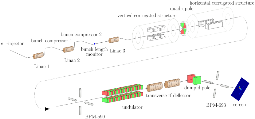
In Fig. 2 we sketch the LCLS beam line, where we focus on the RadiaBeam/SLAC dechirper and the diagnostics used in the measurements of this report. At the right in the top row, after the injector and linacs, we show the dechirper region, including the vertical dechirper module, followed by a quadrupole, and then the horizontal dechirper module. Note that the relative scale of distances in the sketch is greatly distorted; e.g. in reality the linacs are much longer than the other objects in the figure. The measurements described in this report have the vertical dechirper jaws opened wide, and use only the horizontal module, which kicks the beam horizontally (in ). In our measurements, the first BPM past the dechirper, BPM 590, at a distance of m from the dechirper center, is used to measure the wake kick; note that there is only drift space between dechirper and BPM.
During the two-plate measurements, described first below, the beam was very stable. After the transverse scans in the dechirper were taken, the current profile of the beam was measured using the X-band transverse RF-deflector (XTCAV) Ding et al. (2011) and its screen, both located downstream of the undulator. The bunch form was needed for the theoretical calculations.
During the single plate measurements, described below, the shot-by-shot bunch length is measured using the coherent edge radiation generated in the last bend of the final bunch compressor, BC2 (located just before Linac 3; see Fig. 2) Loos et al. (2007). To compare with these measurements, we use the formulas assuming a uniform bunch distribution. Supporting longitudinal measurements use BPM 693, located downstream in the beam dump region, to measure energy change (where dispersion cm).
It is important to note that in the RadiaBeam/SLAC dechirper, the jaws are independently adjustable at both ends. Although, in setup, we normally endeavor to align them parallel to each other and to the beam motion, we expect to inevitably end up with a small amount of residual taper.
IV Two-plate measurements
For the first measurement we set the half gap between the jaws to mm. Here charge pC and energy GeV. We keep the beam fixed, scan the dechirper across the beam, and measure the offset at BPM 590, . The results are given in Fig. 3, where the abscissa is the offset of the beam with respect to the dechirper axis, (a positive offset gives a positive kick). The figure shows the data (plotting symbols with error bars) and calculations (the curves). Each data point represents the average of 40 shots, with error bars showing one standard deviation. (However, in this and some following plots, the error bars are so small as to not be visible.) The bunch shape (with head to the left) as obtained from the XTCAV screen, is given in the inset figure.
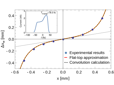
The first thing that we note is that the data set is good, in that the nine data points trace out a smooth, nearly perfectly anti-symmetric curve about the origin, which is theoretically required in a two-plate dechirper that is symmetric in . For the scale of the wake effect, note that a value of mm corresponds to an average kick of kV.
For the comparison calculations, we first numerically performed the wake convolution (Eq. 1) with the measured bunch shape and the wake function (Eqs. 6, 7), to obtain the voltage ; then the result is given by . In a second calculation, we used the analytical solution assuming a uniform bunch distribution (Eqs. 10, 11) to obtain the deflection . In this case we need an effective full bunch length . This parameter was obtained from the measured bunch shape as , with the numerically obtained, rms width (in time) of the bunch distribution. This calculation yields an effective peak current of kA and full length of m.
In Fig. 3 we plot the two calculation results on the same plot as the data. However, to obtain a good fit to the data, we changed the half-aperture parameter in the calculations by %. The straight slanted line in the figure gives the slope of the calculations at the origin. We note that the analytical formula assuming a uniform bunch distribution (the orange curve) is almost identical to the more involved convolution calculation (the black, dashed line). The analytical formula also agrees well with the measured data, except for the % scale factor. At the moment we do not understand the source of the discrepancy. If it is an error in the measurement, it may be due to the inaccuracy of knowing the jaw separation and/or an unknown tilt in the jaws.
We repeat the measurement, but now with half gap mm, charge pC, and energy GeV. The data is shown in Fig. 4 (the plotting symbols), with the error bars again small and barely visible. Note that the data points, at first, were shifted upward in the figure, by 40 m, to yield zero kick on axis; and then, to make the data anti-symmetric, they were shifted to the right by 35 m. Note that a value of mm here corresponds to a kick of kV.
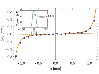
For the comparison calculation, we used the analytical solution assuming a uniform bunch distribution. From the bunch shape measured by XTCAV (see inset) we find the effective peak current and full bunch length as before; the results are kA and m. To obtain a good fit to the data, we changed the half-aperture parameter in the calculations by %. The straight, dashed line gives the slope of the wake at the origin, which we see is much smaller than before. The wake effect over most of the measured range is quite small; it only begins to become significant for mm. The agreement between theory and measurement is quite good.
V Single jaw measurements
With the beam passing by a single jaw of the dechirper, its offset at BPM 590, , was measured as function of distance of the beam from the jaw, . One set of measurements used the north jaw of the horizontal dechirper module, the other used the south jaw. Careful setup of the beam allowed the electron bunch to be much closer to the jaw (than in the two-plate examples above), resulting in a stronger induced wakefield. The recording of measurements per scan step allowed for aggressive filtering with respect to incoming orbit and beam current (using the coherent edge radiation, bunch length monitor). For the north (south) jaw data presented below, we ended up keeping more than 25 (50) data points, except when the beam was 0.5 mm or closer to the jaw, when the number of good points dropped to .
The beam parameters were charge pC, peak current kA, which implies that the full bunch length m; and energy GeV. To clearly know the zero in kick, we included data points with the beam many millimeters from the jaw. Unlike in the two-plate measurements, in the single plate case we can’t use symmetry to help judge the goodness of the data. A fit of the model, Eqs. 10, 11, to the measurements was performed, where we allow for an overall shift in , denoted by .
At the same time as measuring the transverse kick, as a consistency check, we measured the longitudinal wake effect using a downstream BPM in a dispersive region, BPM 693. This gives us the average energy loss of the beam to the wakefields. Fitting this data to the longitudinal formulas in the same way, and comparing the fitted offset with that of the transverse measurement gives us a better idea of the accuracy of the analytical models. From the measurements we obtain the energy loss as , with the measured offset and the dispersion at the BPM 693 (here cm). For the calculations, it is given by , with the loss factor derived in Appendix A, in Eq. 18.
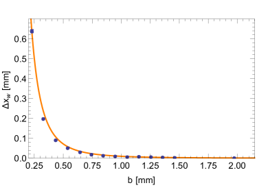
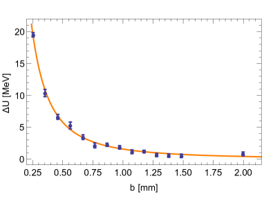
In Fig. 5, the top plot, we present the north jaw transverse measurement results. Note that for the single plate measurements, indicates a kick toward the jaw. A value of mm corresponds to a kick of kV. We see that the fit of the theory (the curve) to the data (the plotting symbols) is good. The fit gives an overall shift of m, and the data in the plot has been shifted by this amount. In Fig. 5, the bottom plot, we present the north jaw energy measurements. We note that there is more scatter in the energy loss data than in the transverse kick data. We see that the fit of the theory to the data again is good. The fit gives an overall shift of m (and, like before, the data in the plot has been shifted by this amount). We see that, in both cases, the theory agrees well with the measurements, and the fitted shifts also are in reasonable agreement with each other.
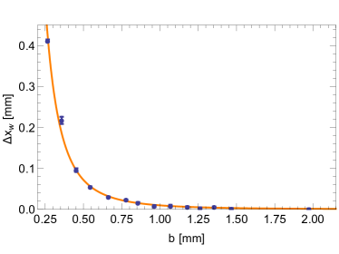
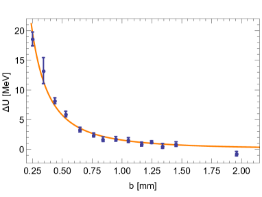
The measurements were repeated with the south jaw, and the results are shown in Fig. 6. We see that, in the energy measurements of the first two points, the standard deviation of error is quite large; this is partly because the number of accepted scans for these points is small, only 10 and 8, respectively. From the figure we see that the fits to the data again are good. This time the fitted shifts are m (for the transverse kick data) and m (for the longitudinal data). Again the fitted shifts are in reasonable agreement with each other.
Before leaving this topic, we should mention that we have made two assumptions in the analysis: (1) that the beam passes by the dechirper jaw with little – tilt, and (2) that the jaw itself is not tilted. The beam is likely not tilted by much, but as to the jaw tilt, we don’t have a good estimate of it. We can just say that the good agreement with the data, and the reasonably good agreement of the fitted shifts for both data sets, are signs that the theory is good and so is our understanding of the dechiper jaw orientation. The same holds true for the double jaw measurements. Expected deviations are below m.
VI Conclusions
The RadiaBeam/SLAC dechirper has been installed at the Linac Coherent Light Source (LCLS). Rather than its use as a dechirper, it is the strong transverse kick, induced when the beam passes by off axis, that has received the most interest. This way of using the dechirper has already been employed to e.g. facilitate the production of intense, two-color photon beams for users Lutman et al. (2016), and is currently being used to develop a diagnostic for attosecond bunch length measurements Novokhatski (2015). Thus, for the LCLS, measurements of the strength of the transverse wakefields in this device is an important task that increases our understanding of the dechirper and facilitates our using it in novel ways. In this report, we present the first systematic measurements of the transverse wakefields in a dechirper, when excited by a bunch with the short pulse duration and high energy found in an X-ray FEL.
We have presented measurements of wake kick as function of beam offset for a bunch passing between the two plates of the horizontal dechirper module and compared with analytical calculations. For two example half-gap settings, we found good agreement between theory and measurement, once the aperture (in the calculations) was adjusted by % and %, respectively.
We repeated the measurement for the case of a beam passing by each of the jaws of the horizontal dechirper module separately (with the other jaw parked far from the beam). We found good agreement between theory and measurement when we allowed for an overall offset in distance of the bunch from the jaw, . The fitted offsets were () m in the north (south) dechirper module jaw. By simultaneously measuring the longitudinal wake effect and performing the corresponding fitting, we found that () m in the north (south) jaw. We consider this good agreement in offsets between the transverse and longitudinal results.
We have seen good agreement between the measured and calculated wake kicks, after a parameter was slightly adjusted in the calculations: the half-gap in the case of two-plates and the beam shift in offset in the case of a single plate. Besides the possibility of inaccuracy in the theory, these discrepancies can be due to measurement error in e.g. plate offset and plate tilt. Nevertheless, the agreement we do see—between measurement and theory—indicates that the theory and our understanding of the dechirper jaw orientation (during the measurement) were both quite good.
In Appendix A we derived analytical formulas for the average longitudinal and transverse wake kicks excited by a short, uniform bunch passing through two-plates (or by a single plate) of a dechirper. In analyzing the first, two-plate measurement example, we demonstrated that these formulas agree almost perfectly with the more accurate, convolution method applied to an LCLS-type bunch.
Acknowledgments
We thank RadiaBeam for building for us the RadiaBeam/SLAC dechirper, and for their support in installing and commissioning it at the LCLS. We also thank the SLAC operators for helping us make these experiments a success. Work supported in part by the U.S. Department of Energy, Office of Science, Office of Basic Energy Sciences, under Contract No. DE-AC02-76SF00515 and DE-SC0009550.
Appendix A Average Wake for Uniform Bunch Distribution, Analytical Model
Analytical formulas were developed for the longitudinal and transverse point charge wakes, for the cases of beam between two dechirper plates Bane et al. (2016a) and near a single plate Bane et al. (2016b). These formulas were shown to agree well with numerical simulations. For a line-charge or pencil beam (one with small transverse extent) with a uniform longitudinal distribution, it turns out that the average longitudinal and transverse wakefield kicks also are given by simple analytical expressions. We derive these expressions here.
Transverse
The bunch wake is given by the convolution of the point charge wake and the bunch distribution. If the longitudinal bunch distribution is uniform of length , , where (0), for (), the kick factor—the average of the transverse bunch wake—is given by
| (13) |
where we used as given in Eq. 6; here
| (14) |
Longitudinal
The longitudinal point charge wake, for a beam between two dechirper plates separated by distance , or offset a distance from a single plate, is given in the form Bane et al. (2016a)
| (15) |
with constants and the longitudinal scale factor . In the case of a beam between two plates, the constants are given by
| (16) |
In the case of a beam near a single plate, the constants are Bane et al. (2016b)
| (17) |
For a uniform bunch distribution, the loss factor—the average of the longitudinal bunch wake—is given by
| (18) |
with
| (19) |
References
- Emma et al. (2010) P. Emma, R. Akre, J. Arthur, R. Bionta, C. Bostedt, J. Bozek, A. Brachmann, P. Bucksbaum, R. Coffee, F.-J. Decker, Y. Ding, D. Dowell, S. Edstrom, A. Fisher, J. Frisch, S. Gilevich, J. Hastings, G. Hays, Ph. Hering, Z. Huang, R. Iverson, H. Loos, M. Messerschmidt, A. Miahnahri, S. Moeller, H.-D. Nuhn, G. Pile, D. Ratner, J. Rzepiela, D. Schultz, T. Smith, P. Stefan, H. Tompkins, J. Turner, J. Welch, W. White, J. Wu, G. Yocky, and J. Galayda, “First lasing and operation of an angstrom-wavelength free-electron laser,” Nat Photon 4, 641–647 (2010).
- Krinsky and Huang (2003) S. Krinsky and Z. Huang, “Frequency chirped self-amplified spontaneous-emission free-electron lasers,” Phys. Rev. ST Accel. Beams 6, 050702 (2003).
- Saldin et al. (2006) E. L. Saldin, E. A. Schneidmiller, and M. V. Yurkov, “Self-amplified spontaneous emission fel with energy-chirped electron beam and its application for generation of attosecond x-ray pulses,” Phys. Rev. ST Accel. Beams 9, 050702 (2006).
- Dohlus et al. (2008) M. Dohlus, J. Rossbach, and P. Schmüser, Ultraviolet and Soft X-Ray Free-Electron Lasers: Introduction to Physical Principles, Experimental Results, Technological Challenges (Springer Publishing Company, Incorporated, Hamburg, 2008).
- Bane and Stupakov (2012) K. Bane and G. Stupakov, “Corrugated pipe as a beam dechirper,” Nucl. Inst. Meth. A 690, 106 (2012).
- Lutman et al. (2016) Alberto A. Lutman, Timothy J. Maxwell, James P. MacArthur, Marc W. Guetg, Nora Berrah, Ryan N. Coffee, Yuantao Ding, Zhirong Huang, Agostino Marinelli, Stefan Moeller, and Johann C. U. Zemella, “Fresh-slice multicolour x-ray free-electron lasers,” Nat Photon 10, 745–750 (2016).
- Qin et al. (2017) Weilun Qin, Yuantao Ding, Alberto Lutman, and Yu-Chiu Chao, Generation of two-color X-ray free-electron lasers using a matching-based fresh-slice method, Tech. Rep. SLAC-PUB-16988 (SLAC, 2017).
- Bettoni et al. (2016) S. Bettoni, P. Craievich, A. A. Lutman, and M. Pedrozzi, “Temporal profile measurements of relativistic electron bunch based on wakefield generation,” Phys. Rev. Accel. Beams 19, 021304 (2016).
- Novokhatski (2015) A. Novokhatski, “Wakefield potentials of corrugated structures,” Phys. Rev. ST Accel. Beams 18, 104402 (2015).
- Emma et al. (2014) P. Emma, M. Venturini, K.L.F. Bane, G. Stupakov, H.-S. Kang, M.S. Chae, J. Hong, C.-K. Min, H. Yang, T. Ha, W.W. Lee, C.D. Park, S.J. Park, and I.S. Ko, “Experimental demonstration of energy-chirp control in relativistic electron bunches using a corrugated pipe,” Phys. Rev. Lett. 112, 034801 (2014).
- Lu et al. (2016) Chao Lu, Feichao Fu, Tao Jiang, Shengguang Liu, Libin Shi, Rui Wang, Lingrong Zhao, Pengfei Zhu, Zhen Zhang, and Dao Xiang, “Time-resolved measurement of quadrupole wakefields in corrugated structures,” Phys. Rev. Accel. Beams 19, 020706 (2016).
- Guetg et al. (2016) M. W. Guetg, K. L. F. Bane, A. Brachmann, A. S. Fisher, M. A. Harrison, Z. Huang, R. Iverson, P. Krejcik, A. A. Lutman, T. J. Maxwell, A. Novokhatski, M. Ruelas, G. Stupakov, J. Zemella, and Z. Zhang, “Commissioning of the radiabeam/slac dechirper,” in Proceedings of the 4th International Particle Accelerator Conference (Busan, Korea, 2016) pp. 824–826.
- Bane et al. (2016a) Karl Bane, Gennady Stupakov, and Igor Zagorodnov, “Analytical formulas for short bunch wakes in a flat dechirper,” Phys. Rev. Accel. Beams 19, 084401 (2016a).
- Zagorodnov et al. (2015) I. Zagorodnov, K. L. F. Bane, and G. Stupakov, “Calculation of wakefields in 2d rectangular structures,” Phys. Rev. ST Accel. Beams 18, 104401 (2015).
- Bane et al. (2016b) K. Bane, G. Stupakov, and I. Zagorodnov, Wakefields of a Beam near a Single Plate in a Flat Dechirper, Tech. Rep. SLAC-PUB-16881 (SLAC, 2016).
- Bane and Stupakov (2015) Karl Bane and Gennady Stupakov, “Using surface impedance for calculating wakefields in flat geometry,” Phys. Rev. ST Accel. Beams 18, 034401 (2015).
- Ding et al. (2011) Y. Ding, C. Behrens, P. Emma, J. Frisch, Z. Huang, H. Loos, P. Krejcik, and M-H. Wang, “Femtosecond x-ray pulse temporal characterization in free-electron lasers using a transverse deflector,” Phys. Rev. ST Accel. Beams 14, 120701 (2011).
- Loos et al. (2007) H. Loos, T. Borden, P. Emma, J. Frisch, and J. Wu, “Relative bunch length monitor for the linac coherent light source (lcls) using coherent edge radiation,” in Proceedings of the Particle Accelerator Conference (PAC 07) (Albuquerque, NM, 2007) pp. 4189–4191.