Fast, large-scale hologram calculation in wavelet domain
Abstract
We propose a large-scale hologram calculation using WAvelet ShrinkAge-Based superpositIon (WASABI), a wavelet transform-based algorithm. An image-type hologram calculated using the WASABI method is printed on a glass substrate with the resolution of pixels and a pixel pitch of m. The hologram calculation time amounts to approximately 354 s on a commercial CPU, which is approximately 30 times faster than conventional methods.
keywords:
Computer-generated hologram , Electroholography , Hologram , Holography , Holographic displayHolograms can be calculated by simulating a light wave emitted from three-dimensional (3D) objects. The development of an ideal 3D display can be expected when these holograms are displayed on a spatial light modulator (SLM) [1]. Unfortunately, this 3D display has the disadvantages that the size and viewing area of the 3D objects are small and narrow. This has been a hindrance to their practical use; however, in recent years, several techniques to address these issues have been proposed. A common factor in these techniques is that to observe the 3D objects with a wide viewing angle and large size by multiple observers, it is necessary to calculate a hologram with a large number of pixels and display it spatially [2, 3, 4] or temporally [5]. In other techniques, hologram printers capable of printing large-scale holograms with minute pixel pitch have been actively employed to reproduce 3D objects with a wide viewing area and large size [6, 7, 8, 9, 10].
The hologram calculation time for reconstructing 3D objects with wide viewing angles and large size is considerably lengthy. Various fast hologram calculation methods have been proposed with procedures of 3D object expression. In the case of 3D objects represented by polygons, tilted diffraction calculation [11] can effectively compute a hologram. A holographic stereogram [12, 13, 14, 15] can be used when 3D objects are expressed in multi-view images. In the case that 3D objects are represented by an RGB-D image, a hologram calculation using diffraction calculation of cross sectional images generated from the RGB-D images has been proposed [16] .
For 3D objects represented by point light sources, a hologram can be calculated by adding light waves from each point light source on the hologram plane. Many acceleration methods for the point light source model have been proposed, suich as an image hologram method [17], look-up table methods (LUT) [18, 19], and wavefront recording plane methods [20, 21]. Recently, we proposed WAvelet ShrinkAge-Based superpositIon (WASABI), a wavelet transform-based method [22, 23]. This method superimposes light waves of point light sources in a wavelet domain. However, although the WASABI method has shown that hologram calculation can be efficiently performed using a small-scale hologram of pixels, thus far, the implementation of large-scale hologram calculations has not been accomplished.
In this study, we generate a large-scale hologram calculation using the WASABI method. An image-type hologram calculated using the WASABI method is printed on a glass substrate. The resolution of the hologram is pixels with the pixel pitch of m. The calculation time of the hologram is approximately 354 s on a commercial CPU. The calculation is capable of a 30-factor acceleration compared to conventional methods.
1 Large-scale hologram calculation using WASABI method
A hologram can be calculated by adding light waves emitted from each object point on the hologram plane. The following equation is used for the calculation:
| (1) |
where , is the total number of the point light sources, is the coordinate of the hologram, and are the coordinate and the light intensity of -th point light source, respectively. is the wave length, is the distance between -th object point and , and is the point spread function (PSF) at the position of an object point. Although this calculation is simple, when the PSF is distributed over the entire hologram, the calculation complexity is where the number of pixels of the hologram is . Therefore, this accounts for the greatest calculating cost among hologram calculations.
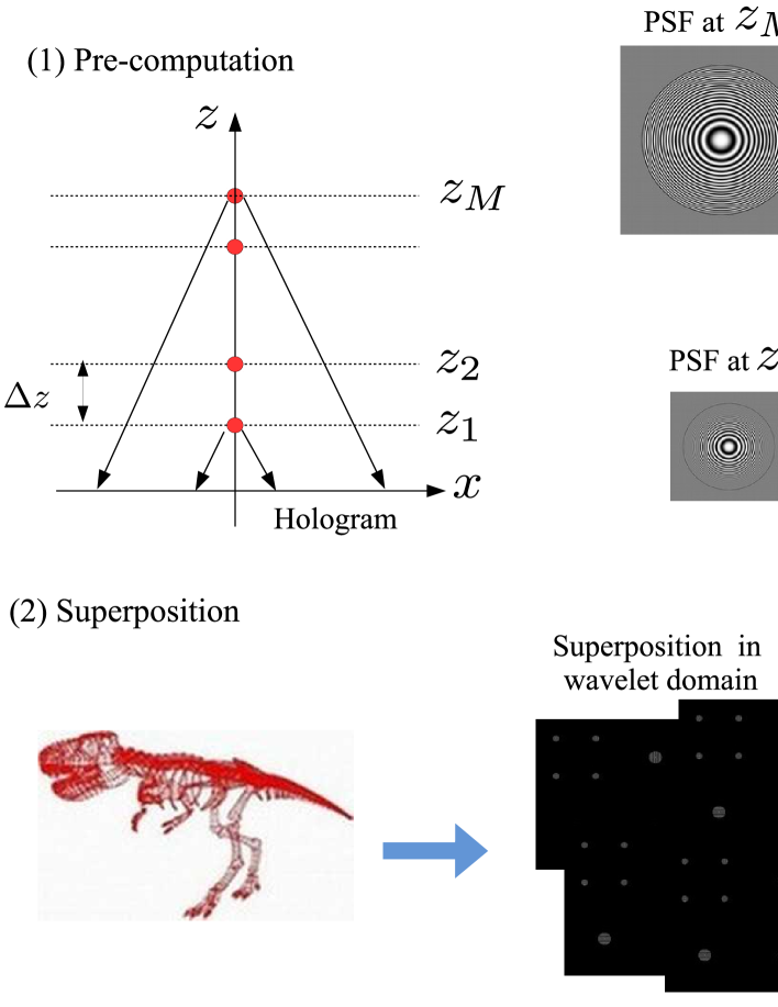
The WASABI method can reduce this computation amount via applying the wavelet transform to the PSF and by superposing the PSFs in the wavelet domain [22]. Figure 1 shows the calculation steps of the WASABI method. The calculation steps are explained as follows:
-
1.
Pre-computation: We pre-compute PSFs by where is the PSF radius of the -th object point and when , otherwise 0. The depth direction of the pre-calculated PSFs are discretized by and the PSFs are converted to wavelet-domain PSFs using fast wavelet transform (FWT). We select strong coefficients among the wavelet-domain PSF and store them in the LUT. In this study, is determined by where is the selectivity.
-
2.
Superposition: The superposition corresponding to Eq.(1) in the wavelet domain is performed using the coefficients stored in the LUT.
-
3.
Inverse transformation: The superposed result is converted to the space domain using the inverse FWT.
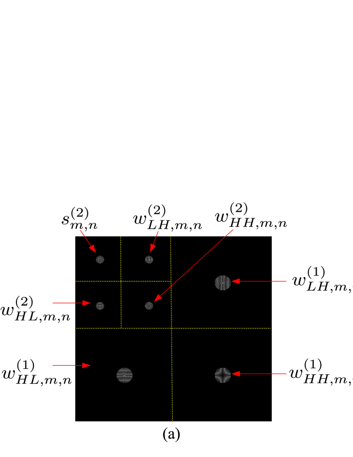
As shown in Fig.2(a), a wavelet-domain PSF is expressed by the scaling coefficient and three wavelet coefficients , and , where denotes the level of FWT and the subscripts and denote low and high frequencies, respectively. Figure 2(a) shows an example of a wavelet-domain PSF at level 2. In this study, we used coiflets as the wavelets at level 3.
The superposition in the wavelet domain is performed by
| (2) |
where is the coordinate in the wavelet domain, is the Dirac delta function and is the strong coefficients and is the shift weight according to the level of the FWT.
When calculating a large-scale hologram by the WASABI method, we first divide an entire hologram into sub-holograms, as shown in Fig.2(b). This division can considerably reduce the memory usage of a computer as compared with calculating the entire hologram at once. Herein, the number of pixels of the entire hologram is , and the number of pixels for each sub hologram is . The index of the sub holograms currently being calculated is represented by . The calculation performed is explained as follows:
-
1.
Pre-computation: As described above, PSFs for a sub hologram with pixels are converted to the wavelet domain via FWT. strong coefficients are stored in the LUT.
-
2.
Coordinate transformation of object points: The coefficients after FWT are defined for sub-holograms ( pixels), and not for the entire hologram ( pixels). Therefore, the positions of all the object points are shifted relative to the current sub-hologram . Thus, the shift is given as and .
-
3.
Superposition: Using and instead of and in Eq.(2), the superposition is performed by .
-
4.
Inverse transformation: We obtain the sub-hologram at via inverse FWT of . We move to the next sub-hologram.
The large-scale hologram calculation is executed by performing the above steps 2 to 4 for all sub-holograms.
2 Result
We show the performance of a large hologram calculation with pixels of a 3D object with approximately 100,000 object points (95,949 points) using a conventional method and the WASABI method. We used the N-LUT method [19] as the conventional method.
Figure 3(a) shows the setup of the hologram calculation. The hologram is recorded as an image-type hologram, and the 3D object is placed at +15mm to -15mm before and after the hologram plane. The depth of the 3D object is divided by , such that the depth interval is . The sub-holograms have pixels. The reference light is a spherical light placed at =(0mm, 30mm, -400mm). The sampling pitch of the hologram is 1m. The calculated hologram has a complex amplitude. In this study, we convert the complex amplitude hologram to a binary amplitude hologram because we use a hologram printer of Ref.[10].
Figure 3(b) shows numerical reconstructions from the hologram calculated using the conventional and the WASABI methods. The left figure of Fig.3(b) shows the reconstructed images when looking at the hologram from the upper side, and the right figure is reconstructed images when looking at the hologram from the front side. Motion parallax can be confirmed from these reconstructions.
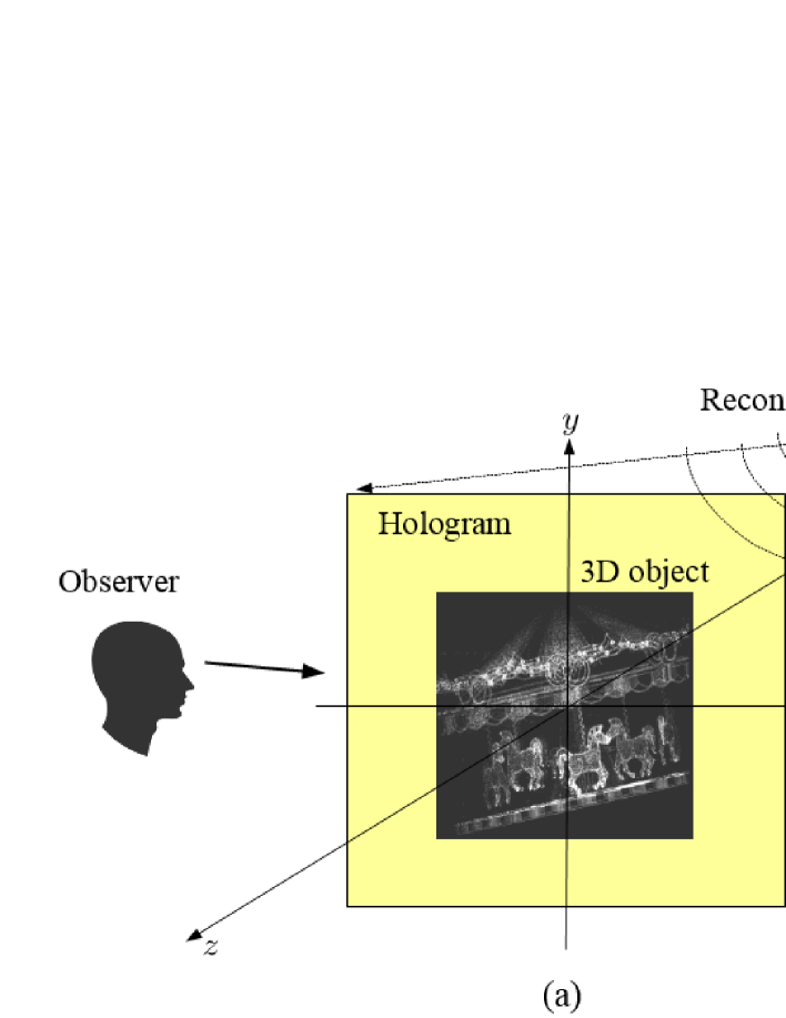
Figure 4(a) shows a hologram calculated via the WASABI method, which is printed on a glass substrate using the hologram printer [10]. The hologram area is 65mm 65mm. Figure 4(b) shows the optical reconstruction of the printed hologram. We used a LED light with a wavelength of 632.8nm as the reconstruction light. The video in supplementary material is recorded while moving a video camera left and right. The viewing angle is approximately 20 degrees.
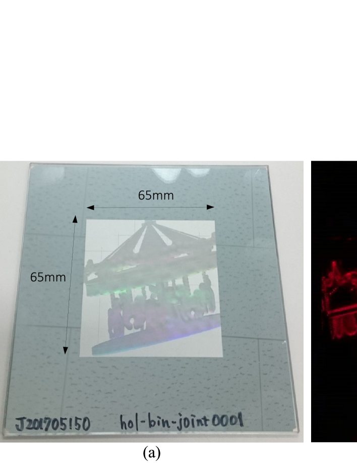
We compare the calculation time of the hologram using the conventional method [19] and the WASABI method. We used an Intel Xeon E5 v3 CPU with 128-GB memory and the Microsoft Visual C++ 2017 as the C++ compiler. In the conventional method, the calculation time is approximately 10,533 s, whereas the WASABI method is capable of calculating the hologram in approximately 354 s. Thus, the WASABI method is approximately 30 times faster than the conventional method. All of the calculations were performed using our wave optics library, CWO++ [24].
3 Conclusion
We executed a large-scale hologram calculation using the WASABI method and compared the calculation time between the conventional and the WASABI methods. An image-type hologram with pixels was calculated using the WASABI method, and we confirmed the optical 3D reconstruction from the hologram printed on a glass substrate. The WASABI method succeeded in accelerating the hologram calculation by approximately 30 times as compared to the conventional method. We used a 3D object with a narrow depth of 3cm. In our upcoming project, we plan to perform a large-scale hologram calculation of 3D objects with deeper depths using the WASABI+WRP method [23].
Acknowledgments
This work was partially supported by JSPS KAKENHI Grant Numbers 16K00151, and Ministry of Education, Culture, Sports, Science, and Technology (MEXT) Strategic Research Foundation at Private Universities (2013-2017). We would like to thank Dr. Hirotaka Nakayama for providing 3D models. This work was supported by Kan-Dai Digital Holo-Studio in Kansai University.
References
- [1] T. C. Poon, ed., Digital Holography and Three-Dimensional Display - Principles and Applications (Springer, 2006).
- [2] M. Stanley et.al., “100-megapixel computer-generated holographic images from Active Tiling: a dynamic and scalable electro-optic modulator system,” Practical Holography XVII and Holographic Materials IX, Proc. SPIE 5005, 247 (2003).
- [3] H. Sasaki, K. Yamamoto, Y. Ichihashi, and T. Senoh, “Image Size Scalable Full-parallax Coloured Three-dimensional Video by Electronic Holography,” Sci. Rep. 4, 4000 (2014).
- [4] P.-A. Blanche et.al., “Holographic three-dimensional telepresence using large-area photorefractive polymer,” Nature 468, 80-83 (2010).
- [5] Y. Takaki and Y. Hayashi, “Increased horizontal viewing zone angle of a hologram by resolution redistribution of a spatial light modulator,” Appl. Opt. 47, D6–D11 (2008).
- [6] M. Yamaguchi, N. Ohyama, and T. Honda, “Holographic three-dimensional printer: new method,” Appl. Opt. 31, 217-222 (1992).
- [7] H. Yoshikawa, and K. Takei, “Development of a compact direct fringe printer for computer-generated holograms,” In Electronic Imaging 2004, International Society for Optics and Photonics, 114-121 (2004).
- [8] Y. Kim, E. Stoykova, H. Kang, S. Hong, J. Park, J. Park, and J. Hong, “Seamless full color holographic printing method based on spatial partitioning of SLM,” Opt. Express 23, 172–182 (2015).
- [9] K. Wakunami, P. Y. Hsieh, R. Oi, T. Senoh, H. Sasaki, Y. Ichihashi, and K. Yamamoto, “Projection-type see-through holographic three-dimensional display,” Nat. commun. 7, 12954 (2016).
- [10] Y. Tsuchiyama and K. Matsushima, “Full-color large-scaled computer-generated holograms using RGB color filters,” Opt. Express 25, 2016-2030 (2017).
- [11] K. Matsushima, H. Schimmel, and F. Wyrowski, “Fast calculation method for optical diffraction on titled planes by use of the angular spectrum of plane waves,” J. Opt. Soc. Am. A 20, 1755-?1762 (2003).
- [12] Y. Ichihashi, R. Oi, T. Senoh, K. Yamamoto, and T. Kurita,“Real-time capture and reconstruction system with multiple GPUs for a 3D live scene by a generation from 4K IP images to 8K holograms,” Opt. Express 20, 21645–21655 (2012).
- [13] M. Yamaguchi, H. Hoshino, T. Honda, and N. Ohyama, “Phase-added stereogram: calculation of hologram using computer graphics technique,” Proc. SPIE 1914, 25–31 (1993).
- [14] K. Wakunami and M. Yamaguchi, “Calculation for computer generated hologram using ray-sampling plane,” Opt. Express 19, 9086-9101 (2011).
- [15] H. Zhang, Y. Zhao, L. Cao, and G. Jin, “Fully computed holographic stereogram based algorithm for computer-generated holograms with accurate depth cues,” Opt. Express 23, 3901–3913 (2015).
- [16] R. Oi, K. Yamamoto, and M. Okui, “Electronic generation of holograms by using depth maps of real scenes,” Practical Holography XXII: Materials and Applications, Proc. SPIE 6912, 69120M (2008).
- [17] H. Yoshikawa, T. Yamaguchi, and R. Kitayama, “Real-time generation of full color image hologram with compact distance look-up table,” OSA Topical Meeting on Digital Holography and Three-Dimensional Imaging 2009, DWC4 (2009).
- [18] M. Lucente, “Interactive computation of holograms using a look-up table,” J. Electron. Imaging 2, 28-34 (1993).
- [19] S. -C. Kim and E. -S. Kim, “Effective generation of digital holograms of three-dimensional objects using a novel look-up table method,” Appl. Opt. 47, D55-D62 (2008).
- [20] T. Shimobaba, N. Masuda and T. Ito, “Simple and fast calclulation algorithm for computer-generated hologram with wavefront recording plane,” Opt. Lett. 34, 3133–3135 (2009).
- [21] P. Tsang, W. -K. Cheung, T.-C. Poon, and C. Zhou, “Holographic video at 40 frames per second for 4-million object points,” Opt. Express 19, 15205–15211 (2011).
- [22] T. Shimobaba and Tomoyoshi Ito, “Fast generation of computer-generated holograms using wavelet shrinkage,” Opt. Express 25, 77-87 (2017).
- [23] D. Arai, T. Shimobaba, T. Nishitsuji, T. Kakue, N. Masuda, and T. Ito, “An accelerated hologram calculation using the wavefront recording plane method and wavelet transform,” Opt. Commun. 393, 107–112 (2017).
- [24] T. Shimobaba, J. Weng, T. Sakurai, N. Okada, T. Nishitsuji, N. Takada, A. Shiraki, N. Masuda, and T. Ito, “Computational wave optics library for C++: CWO++ library,” Comput. Phys. Commun. 183, 1124–1138 (2012).