Substrate effects on transport properties of a biased AA-stacked bilayer graphene
Abstract
The important experimental advances in graphene fabrication and its peculiar transport properties motivated researchers to utilize graphene as a potential basis for the next generation of fast and smart electronic devices. In this article, we investigate the influence of a potential substrate on the transport properties of a biased AA-stacked -- bilayer graphene junction (AA-BLG). Using the Dirac Hamiltonian with the transfer matrix approach we obtain the transmission probabilities and thus the respective conductance. In the presence of the induced mass-term the energy spectrum and the intra-cone transmission drastically change while the inter-cone transmission remains zero. On the other hand, the bias slightly alters the energy spectrum but it significantly affects the transport properties due to its ability to switch on the inter-cone transmission. In addition, we find that Klein tunnelling is attenuated in the presence of the induced mass-term which can improve the carriers confinement in such configurations. Our findings provide possible experimental measurements to determine the interlayer coupling and the induced mass terms in graphene bilayer based on conductance and band structure measurements.
I Introduction
Since its experimental realization in 2004Geim_2007 , graphene and its multilayer systems have triggered an avalanche of interest due to its remarkable electronic, optical and mechanical properties. Such extraordinary properties make graphene a promising material for nanoscale device applications in the future such as its potential use in sensors, detectors, electronics, …etcCastro_Neto_2009 ; Berdiyorov_2016 ; Tit_2017 . . Bilayer graphene exists with two different types of stacking, namely, AB-(Bernal) and AA-stackings (AB-BLG and AA-BLG). Due to the stability of AB-BLG, it has been subjected to considerable theoretical and experimental investigationsOhta_2006 ; Goerbig_2011 ; Abdullah_2016 . Albeit the old belief in the instability of AA-BLG, recent stable samples were successfully realized.Lee_2008 ; Borysiuk_2011 ; de_Andres_2008 ; Liu_2009 . Pristine AA-BLG has a linear gapless energy spectrum which has attracted considerable theoretical interestRakhmanov_2012 ; Mohammadi_2015 ; Chen_2013 ; Chiu_2013 ; Rozhkov_2011 ; Rozhkov_2016 . Different investigations on AA-BLG have been performed such as spin Hall effectDyrda__2014 ; Hsu_2010 , doping effectsSboychakov_2013 , dynamical conductivityTabert2012 , tunneling through electrostatic and magnetic barriersWang_2013 ; Sanderson_2013 , magnon transportOwerre01_2016 , and the influence of spin orbit coupling on the band structureYao_2007 . A recent work also studied the tunneling through an array of electrostatic barriers considering a mass term in the system without a biasRedouani2016 .
Because of the so-called Klein tunneling of Dirac fermions there is no complete confinement in graphene. One way to overcome this problem by introducing a band gap in the energy spectrum which can be achieved, for example, using slow Li+ ions or perpendicular electric field in single-layer graphene and AB-BLG, respectivelyOostinga_2007 ; Ohta_2006 ; Zhou_2007 ; Ryu_2016 . Additionally, it has been observed that substrates can also play a major role in the electronic confinement of single layer graphene due to the substrate-induced band gap of the order meVWang_2015 ; San_Jose_2014 ; Kindermann_2012 ; Song_2013 ; Jung_2015 ; Nevius_2015 ; Zarenia_2012 . The width of the band gap depends on the mass term induced by the substrates whose magnitude can be of the order meV depending on the type of the substrate Uchoa_2015 . Recently, a study showed that Hall phase can be realized in gapped AB-BLG when mass terms are considered in both layersZhai2016 . Such mass terms are induced by dielectric materials such as hexagonal boron nitride (h-BN) or SiC.
In the present work we investigate the substrate effect on intra- and inter-cone transport of biased AA-BLG. Considering the mass term to be the same in both layers of AA-BLG leads to opening a gap around the lower and upper cones whereas the whole spectrum remains gapless. The presence of a mass term can greatly affect the intra-cone transport. However, the total conductance of the system remains almost unchanged. Biasing the two layers of AA-BLG allows inter-cone transition due to coupling the upper and lower cones. We also found that including a mass term in the system can significantly attenuate Klein tunneling in AA-BLG systems.
II Electronic Model
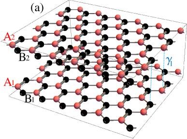
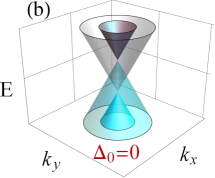
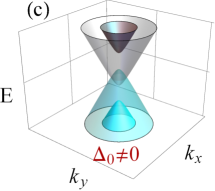
Single layer graphene has a hexagonal crystal structure and comprises two atoms and in its unit cell whose interatomic distance is nm and its intra-layer coupling is eVZhang_2011 . In the AA-stacked graphene bilayer the two single layer graphene are placed exactly on top of each other such that atoms and in the top layer are located directly above the and atoms in the bottom layer with a direct inter-layer coupling Lobato_2011 , see Fig. 1(a). The energy spectrum with and without the mass term are shown in Figs. 1(b, c), respectively. We see that the mass term introduces a gap in the vicinity of the upper and lower cones. Notice that the whole spectrum remains gapless unless the mass-term amplitude exceeds the inter-layer coupling. The continuum approximation of the Hamiltonian which describing electrons near the Dirac point in AA-BLG taking into account the mass term readsTabert2012
| (1) |
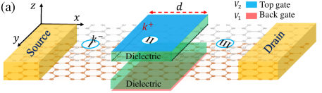
where is the momentum operator and . The substrate effect is represented by the mass-term whose amplitude is where denotes the mass term in the first and second layer, respectively. Note that we here assume zero inter-layer mass-term difference which requires . and describe the electrostatic potential strength and the bias, respectively, subjected to region whose width is and can be modulated by external voltage gates as shown in Fig. 2(a). is the electrostatic potential on the -th layer and m/s is the Fermi speed of charge carriers in the graphene sheet. It is well known that substrates induce a mass term of opposite sign on sublattices and , respectively. A simplification can be made to the Hamiltonian in Eq. (1), by applying unitary transformation that forms symmetric and anti-symmetric combination of the top and bottom layer. This results in a Hamiltonian in the basis .
Introducing the length scale , which represents the inter-layer coupling length nm, allows us to define the following dimensionless quantities:
As a result of the translational invariance along the direction, the momentum along this direction is a conserved quantity and, hence, the wavefunction in the new basis can be written as
| (2) |
where stands for transpose. From Schrodinger equation , one obtains four coupled differential equations that can be reduced to a single second order differential equation for as follows
| (3) |
where
| (4) |
with and . The wave vectors and can be expressed in terms of the incident angle as
| (5) |
From Eq. (4), it follows that the energy spectrum for the system is given by
| (6) |
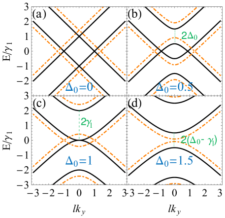
where . In Fig. 3. We show the energy spectrum of the AA-BLG for different values of the system parameters. Pristine AA-BLG has a linear energy spectrum with two up-down Dirac cones shifted by , which is in this case as shown in Fig. 3(a) by the solid black curves. When AA-BLG is subjected to a perpendicular electric field (biased AA-BLG) the two Dirac cones are slightly shifted and located at , see dotted-dashed orange curves in Fig. 3(a). Fig. 3(b) is the same as Fig. 3(a) but in the presence of mass-term amplitude and the spectrum exhibits a shift in the bands in the vicinity of the upper and lower Dirac cones. Note that the whole spectrum remains gapless. When the mass-term amplitude is the same as the interlayer coupling, i.e. , the spectrum becomes parabolic and resembles that of pristine AB-stacked BLG. The two lower bands touch each other at while the other two are spaced from the zero energy by , see Fig. 3(c). Considering the mass-term amplitude that exceeds the inter-layer coupling results in opening a direct gap in the energy spectrum of magnitude as shown in Fig. 3(d).
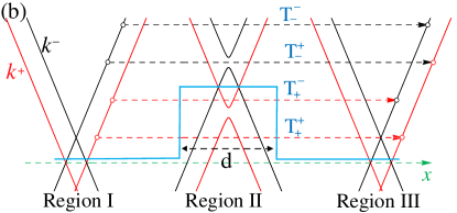
To calculate the transmission probabilities, the desired solution in each region must be obtained. Then, implementing the transfer matrix together with appropriate boundary conditions gives the transmission and reflection probabilitiesBarbier01_2010 ; Van_Duppen01_2013 ; Abdullah_2017 . The different possible intra- or inter-cone transitions processes through the junctions are described in Fig. 2(b). The zero temperature conductance can be calculated using the Büttiker’s formulaSnyman_2007 ; Blanter_2000
| (7) |
with , represents the transmission probability of a particle incident from the mode (subscript in ) and transmitted to the mode (superscript in ), while defines the length of the sample in the -direction, and . The factor comes from the valley and spin degeneracy in graphene. The total conductance of the system is the sum through all available channels.
III Results and discussion
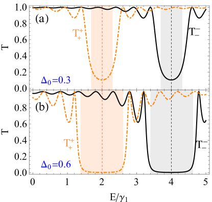
In this section, we first analyze the Fermi energy-dependent behavior of intra- and inter-cone transport. In the absence of the bias only the intra-cone transport is allowed which conducts through the channels and corresponding to the lower and upper cones, respectively. In Fig. (4) we show the transmission probabilities for and with in the left(right) panel. In the absence of the mass-term (i.e. ) and for normal incidence (i.e. ) the lower and upper cone transmission probabilities show perfect tunneling even when the barrier strength is larger than the Fermi energy, see Fig. 4(left panel). In other words, such behaviour is a typical signature of Klein tunneling in graphene. However, introducing the mass-term (i.e. ) results in a significant suppression in the transmission for specific ranges of energy, specifically, in vicinity of lower and upper cones, see Fig. 4(right panel). For the lower (upper) cone channel , the suppression occurs for . Notice that the total charge carrier transmission of the system is non-zero in these energy ranges. To examine thoroughly the effect of substrate on Klein tunneling, we show in Fig. 5 the transmission probabilities of the lower and upper cones for normal incidence. In panel (a) we assume that the substrate induces a mass-term of magnitude while it is doubled in panel (b). We see that the transmission probabilities display different behaviours in this case. Of particular importance we notice that the Klein tunneling is attenuated and rather resonances appear in the transmission probabilities as a results of the finite size effect. These so called Febry-Pérot resonancesSnyman_2007 coincide with the energies given by
| (8) |
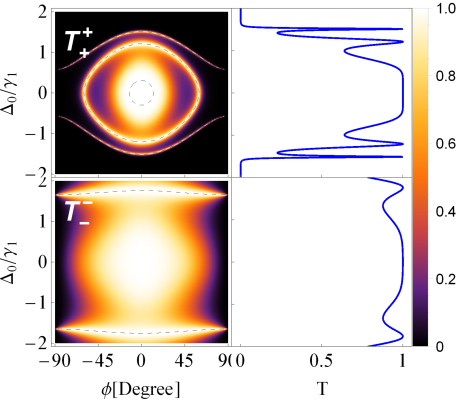
where is the cone index associated with (lower, upper) cones and stands for electron- and hole-like states corresponding to each cone. We superimpose these resonant energies as dashed black curves in Fig. 4. Note that equation (8) is valid for any angle in contrast to the AB-BLG where its validity only holds for normal incidence. We know that, for normal incidence, the presence of Klein and anti Klein tunnelling in single and AB-BLG, respectively, is a direct consequence of the pseudo spin conservation in the system. This means that in AA-BLG the backscattering is not forbidden and a non-zero reflected current can appear at certain energies when considering a mass term. Moreover, the intra-cone transport along the normal incident direction shows a rapid decrease in the vicinity of both cones (inside the barrier, i.e. ), see Fig. 5(a). This decrease can reach zero when a large mass-term amplitude is considered as shown in Fig. 5(b) . In Fig. 6 we show the intra-cone transmission as a function of the mass-term amplitude and the incident angle for a certain energy. For a specific energy, the role of the mass term in the lower and upper cone transmission are distinct as reflected in Fig. 6(left panel). The lower cone transmission channel is completely suppressed for either large mass-term amplitude or large incident angle. While the charge carriers can still conduct for wide ranges of energy and mass-term amplitudes through the upper cone channel . In Fig. 6(right panel) we show the transmission probabilities, associated with each cone, along the normal incidence direction which clarify the suppression in lower cone transmission for large .
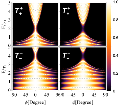
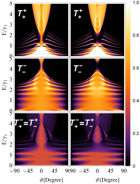
The main role of the bias in the cone-transport can be deduced from the Hamiltonian in Eq. (1), after performing a unitary transformation, where it couples the lower and upper Dirac cones leading to the inter-cone transportAbdullah2017 . To investigate the inter-cone transmission induced by the bias () we show the density plot for the different channels for in the left (right) panel of Fig. 7. The transmission profile in Fig. 7(bottom panels) shows clearly that, due to the bias, scattering between the upper and lower cones is significant. For comparison with the results of a biased AB-BLGVan_Duppen01_2013 , it can be seen here that the scattering channels preserve the angular symmetry in contrast to the case of AB-BLG where such symmetry is broken. This difference is a manifestation of the symmetric and asymmetric inter-layer coupling in the AA-BLG and AB-BLG, respectively. The fringes that appear in are also a consequence of the bias and their number depends on the width of the intermediate region. Such fringes arise due to the well known Fabry-Pérot interference between the two coupled modes. These fringes are not affected when a mass term is considered as can be inferred from the channel in Fig. 7(right panel). In contrast to the intra-cone transport, it is observed that regardless amplitude strength of the mass term, the inter-cone transport channels show a significant transmission in the vicinity of lower and upper cones (inside the barrier) as depicted in Fig. 7(right panel). This can be understood from the bands in Fig. 2(b). For intra-cone channels, for instance , around the lower cone there are (red band in Fig. 2(b)) propagating states outside the barrier but they are absent inside the barrier within the same range of energy. Hence, a gap in the intra-cone channels arises in the vicinity of lower and upper cones. On the other hand, the non-zero transmission associated with the inter-cone channels in the vicinity of the Dirac cones is a manifestation of the availability of states with opposite parity inside the barrier. For example, in the channel the incident charge carriers coincide with the mode and jump to states whose mode is of opposite parity, i.e. . The presence of the inside the barrier in the vicinity of the lower cone, inside the barrier, leads to a significant tunneling in the channel . The same analogy also applies to the channel .
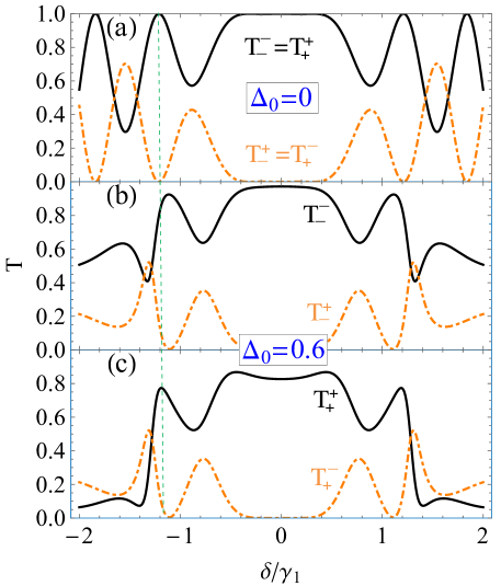
In Fig. 8, we show the intra- (solid black) and inter- (dashed brown) cone transport along the normal incidence direction as a function of the bias for a certain energy. The intra- and inter-cone transport show a certain complementarity such that a maximum in first one coincide with minimum in the latter one as can be seen in Fig. 8(a). Such behaviour is a manifestation of Klein tunneling being preserved which enforces the total transmission of each cone to reach unity at normal incidence. This means that for the lower cone we need and for the upper cone . This condition leads to the equivalence in the intra- and inter-cone channels such that and . Considering the mass term results in an attenuated Klein tunneling and hence breaking the equivalence in the intra-cone channels and as can be inferred from Figs. 8(b, c) (see solid black curves). However, the equivalence in the inter-cone channels is still obtained as can be seen in Figs. 8(b, c) (brown dashed curves) which is a result of the valley degeneracyVan_Duppen01_2013 . Note that the observed complementarity in the intra- and inter-cone channels is also lost as shown in Figs. 8(b, c).
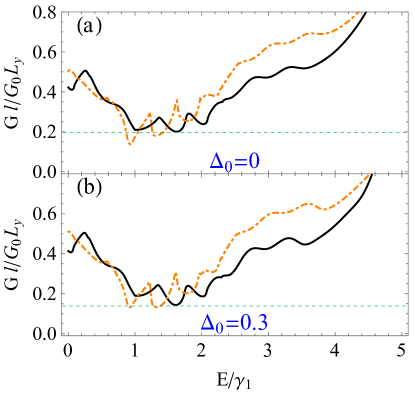
The total conductance of the system as a function of the Fermi energy is shown in Figs. 9 (a,b) for zero and finite mass-term amplitude, respectively. Without bias and by comparing solid black curves in panels (a) and (b), we find that the behaviour of the total conductance remains almost the same. This means that even though the mass term has a significant impact on the intra-cone transport, the total conductance remains almost unchanged when considering the small mass-term amplitude. Note that these two channels, and , cannot be distinguished experimentally. In other words, the measurements will give the total transport of both channels and as a result the effect of the mass term on individual channel cannot be observed. However, the presence of the mass term reduces the overall conductance as indicated by the horizontal dashed green lines in Figs. 9(a,b). In contrast, biasing the system ()Zhou2006 leads to a considerable increase in the overall conductance as clarified by the brown dashed curves in Fig. 9(a,b). We note also that the conductance gets very pronounced as a result of the extra inter-cone channels activated by the bias. The extra peaks appearing in the profile of the conductance with bias are attributed to the fringes in the lower cone channel (see in Fig. 7) as a result of the finite-size effect.
IV Summary
In summary, we have theoretically investigated the quantum transport across a biased AA-BLG -- junction. In the presence of an induced mass-term, the intra-cone transport is almost completely suppressed in the vicinity of the upper and lower cones. However, the system remains gapless and the behaviour of the total conductance remains almost the same when considering small mass-term amplitudes. The results also show that the inter-cone transport can only be induced and modulated by introducing a bias. As a result of the induced inter-cone transport, extra resonances appear in transmission profiles of the lower cone which appear in the evanescent modes regime of the upper cone. In general, the bias enhances the overall conductance in the presence or absence of the induced mass-term. Such increase in the conductance, especially for large energies, is attributed to the additional inter-cone channels that can be accessed in the presence of a bias. In contrast to the normal incidence in AA-BLG junction, where we observed an attenuated Klein tunneling in the presence of the mass term.
It is our hope that the results in this article will provide a path for the electrical control of quantum transport in biased AA-BLG-based electronic device taking into account the substrate effect.
Acknowledgment
We acknowledge the support of King Fahd University of Petroleum and Minerals under research group project RG1502-1 & RG1502-2. We also acknowledge the material support of the Saudi Center for Theoretical Physics (SCTP) during the progress of this work. HMA thanks Mohammed M Al Ezzi for the critical readings of the manuscript.
References
- (1) A. K. Geim and K. S. Novoselov, Nat. Mater. 6, 183 (2007).
- (2) A. H. C. Neto, F. Guinea, N. M. R. Peres, K. S. Novoselov, and A. K. Geim, Rev. Mod. Phys. 81, 109 (2009).
- (3) G. R. Berdiyorov, H. Abdullah, M. A. Ezzi, G. V. Rakhmatullaeva, H. Bahlouli, and N. Tit, AIP Advances 6, 125102 (2016).
- (4) N. Tit, M. M. A. Ezzi, H. M. Abdullah, M. Yusupov, S. Kouser, H. Bahlouli, and Z. H. Yamani, Mater. Chem. Phys. 186, 353 (2017).
- (5) T. Ohta, A. Bostwick, T. Seyller, K. Horn, and E. Rotenberg, Science 313, 951 (2006).
- (6) M. O. Goerbig, Rev. Mod. Phys. 83, 1193 (2011).
- (7) H. M. Abdullah, M. Zarenia, H. Bahlouli, F. M. Peeters, and B. V. Duppen, Europhys. Lett. 113, 17006 (2016).
- (8) J.-K. Lee, S.-C. Lee, J.-P. Ahn, S.-C. Kim, J. I. B. Wilson, and P. John, J. Chem. Phys. 129, 234709 (2008).
- (9) J. Borysiuk, J. Sołtys, and J. Piechota, J. Appl. Phys. 109, 093523 (2011).
- (10) P. L. de Andres, R. Ramírez, and J. A. Vergés, Phys. Rev. B 77, 045403 (2008).
- (11) Z. Liu, K. Suenaga, P. J. F. Harris, and S. Iijima, Phys. Rev. Lett. 102, 015501 (2009).
- (12) A. L. Rakhmanov, A. V. Rozhkov, A. O. Sboychakov, and F. Nori, Phys. Rev. Lett. 109, 206801 (2012).
- (13) Y. Mohammadi and B. A. Nia, Solid State Commun. 201, 76 (2015).
- (14) R.-B. Chen, Y.-H. Chiu, and M.-F. Lin, Carbon 54, 268 (2013).
- (15) C.-W. Chiu, S.-C. Chen, Y.-C. Huang, F.-L. Shyu, and M.-F. Lin, Appl. Phys. Lett. 103, 041907 (2013).
- (16) A. Rozhkov, G. Giavaras, Y. P. Bliokh, V. Freilikher, and F. Nori, Phys. Rep. 503, 77 (2011).
- (17) A. Rozhkov, A. Sboychakov, A. Rakhmanov, and F. Nori, Phys. Rep. 648, 1 (2016).
- (18) A. Dyrdał and J. Barnaś, Solid State Commun. 188, 27 (2014).
- (19) Y.-F. Hsu and G.-Y. Guo, Phys. Rev. B 82, 165404 (2010).
- (20) A. O. Sboychakov, A. L. Rakhmanov, A. V. Rozhkov, and F. Nori, Phys. Rev. B 87, 121401 (2013).
- (21) C. J. Tabert and E. J. Nicol, Phys. Rev. B 86, 075439 (2012).
- (22) D. Wang and G. Jin, J. Appl. Phys. 114, 233701 (2013).
- (23) M. Sanderson, Y. S. Ang, and C. Zhang, Phys. Rev. B 88, 245404 (2013).
- (24) S. A. Owerre, J. Phys.: Condens. Matter 28, 47LT02 (2016).
- (25) Y. Yao, F. Ye, X.-L. Qi, S.-C. Zhang, and Z. Fang, Phys. Rev. B 75, 041401 (2007).
- (26) I. Redouani and A. Jellal, Mater. Res. Express 3, 065005 (2016).
- (27) J. B. Oostinga, H. B. Heersche, X. Liu, A. F. Morpurgo, and L. M. K. Vandersypen, Nat. Mater. 7, 151 (2007).
- (28) S. Y. Zhou, G.-H. Gweon, A. V. Fedorov, P. N. First, W. A. de Heer, D.-H. Lee, F. Guinea, A. H. C. Neto, and A. Lanzara, Nat. Mater. 6, 770 (2007).
- (29) M. Ryu, P. Lee, J. Kim, H. Park, and J. Chung, Nanotechnology 27, 31LT03 (2016).
- (30) W.-X. Wang, L.-J. Yin, J.-B. Qiao, T. Cai, S.-Y. Li, R.-F. Dou, J.-C. Nie, X. Wu, and L. He, Phys. Rev. B 92, 165420 (2015).
- (31) P. San-Jose, A. Gutiérrez-Rubio, M. Sturla, and F. Guinea, Phys. Rev. B 90, 075428 (2014).
- (32) M. Kindermann, B. Uchoa, and D. L. Miller, Phys. Rev. B 86, 115415 (2012).
- (33) J. C. W. Song, A. V. Shytov, and L. S. Levitov, Phys. Rev. Lett. 111, 266801 (2013).
- (34) J. Jung, A. M. DaSilva, A. H. MacDonald, and S. Adam, Nat. Commun. 6, 6308 (2015).
- (35) M. Nevius, M. Conrad, F. Wang, A. Celis, M. Nair, A. Taleb-Ibrahimi, A. Tejeda, and E. Conrad, Phys. Rev. Lett. 115, 136802 (2015).
- (36) M. Zarenia, O. Leenaerts, B. Partoens, and F. M. Peeters, Phys. Rev. B 86, 085451 (2012).
- (37) B. Uchoa, V. N. Kotov, and M. Kindermann, Phys. Rev. B 91, 121412(R) (2015).
- (38) X. Zhai and G. Jin, Phys. Rev. B 93, 205427 (2016).
- (39) F. Zhang, J. Jung, G. A. Fiete, Q. Niu, and A. H. MacDonald, Phys. Rev. Lett. 106, 156801 (2011).
- (40) I. Lobato and B. Partoens, Phys. Rev. B 83, 165429 (2011).
- (41) M. Barbier, P. Vasilopoulos, and F. M. Peeters, Phys. Rev. B 82, 235408 (2010).
- (42) B. V. Duppen and F. M. Peeters, Phys. Rev. B 87, 205427 (2013).
- (43) H. M. Abdullah, A. E. Mouhafid, H. Bahlouli, and A. Jellal, Mater. Res. Express 4, 025009 (2017).
- (44) I. Snyman and C. W. J. Beenakker, Phys. Rev. B 75, 045322 (2007).
- (45) Y. Blanter and M. Büttiker, Phys. Rep. 336, 1 (2000).
- (46) H. M. Abdullah, B. V. Duppen, M. Zarenia, H. Bahlouli, and F. M. Peeters, J. Phys.: Condens. Matter 29, 425303 (2017).
- (47) S. Y. Zhou, G.-H. Gweon, J. Graf, A. V. Fedorov, C. D. Spataru, R. D. Diehl, Y. Kopelevich, D.-H. Lee, S. G. Louie, and A. Lanzara, Nat. Phys. 2, 595 (2006).