Spontaneous surface reserve formation in wicked membranes bestow extreme stretchability
Soft stretchable materials are key for arising technologies such as stretchable electronics [Rogers2010] or batteries [Liu2016], smart textiles [Hu2012], biomedical devices [Minev2015], tissue engineering and soft robotics [Shepherd2011, Lazarus2015]. Recent attempts to design such materials, via e.g. micro-patterning of wavy fibres [Ahn2009] on soft substrates, polymer engineering at the molecular level [sun2012highly] or even kirigami techniques [rafsanjani2017buckling], provide appealing prospects but suffer drawbacks impacting the material viability: complexity of manufacturing, fatigue or failure upon cycling, restricted range of materials or biological incompatibility. Here, we report a universal strategy to design highly stretchable, self-assembling and fatigue-resistant synthetic fabrics. Our approach finds its inspiration in the mechanics of living animal cells that routinely encounter and cope with extreme deformations, e.g. with the engulfment of large intruders by macrophages [Lam2009], squeezing and stretching of immune cells in tiny capillaries [Guillou2016] or shrinking/swelling of neurons upon osmotic stimuli [Morris2001]. All these large instant deformations are actually mediated and buffered by membrane reserves available in the form of microvilli, membrane folds or endomembrane that can be recruited on demand [Guillou2016, Raucher1999]. We synthetically mimicked this behavior by creating nanofibrous liquid-infused tissues spontaneously forming surface reserves whose unfolding fuels any imposed shape change. Our process, relying only on geometry, elasticity and capillarity, allows to endow virtually any material with high stretchability and reversibility, making it straightforward to implement additional mechanical, electrical or chemical functions. We illustrate this with proof-of-concept activable capillary muscles, adaptable slippery liquid infused porous surfaces and stretchable basic printed electronic circuits.
Geometry and elasticity of thin objects are intimately linked, so that metallic wires with identical diameter but with different shapes (e.g. straight or curly as a spring) will contrast markedly in their mechanical response. Nature abounds in such examples where mechanical behavior is entangled with geometry. Leaf geometrical curvature, for example, is critical for some carnivorous plants’ prey-trapping ability. For example, the particular shape adopted by the Venus flytrap’s leaf brings it on the verge of an elastic instability, requiring from an insect only a minute stroke to snap and rush the vegetal jaws – thereby providing the plant with one of the fastest non-muscular movements [Forterre2005].
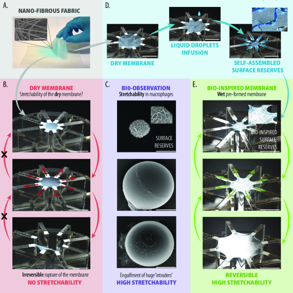
Geometry is also behind the curious mechanical behavior of the capture silk spun by ecribellate spiders: whether stretched or compressed, this fibre remains straight while seemingly adjusting its length, as if telescopic. Actually the pulling force of surface tension allows to coil, spool and pack excess fibre within the glue droplets decorating the thread. These so formed fibre reserves can then be recruited on demand – and confer the thread an apparent extreme strechability of +10,000% [elettro2016drop]. Another example can be found inside our own body with cells which display a particular ability to cope with stretch. Macrophages extending their surface area by a factor 5 to engulf large microbes or cellular debris [Lam2009] (see Fig. 1), patrolling T-lymphocytes stretching by 40% to squeeze into the microvasculature [Guillou2016], hundreds of m sized neuronal projections extruded from 10 m wide neurons [Raucher1999, Dai1995] or osmotic swelling of fibroblast leading to 70% increase in area [Groulx2006] are a few out of many examples of the extreme mechanical sollicitations encountered by living animal cells on a routine basis. This resilience is all the more spectacular that the lytic stretching level at which the plasma membrane ruptures is about 4% [Raucher1999, Nichol1996]. Why do these cells then just not burst under stress? Actually cells have evolved a strategy consisting in storing excess membrane in the form of folds and microvilli [Erickson1976, Majstoravich2004] which can be recruited and deployed on demand. Interestingly, these geometrical corrugations enabling stretching do not fluff the membrane. Cellular tension is indeed preserved thanks to the pulling action of the underlying cortical actin layer [Salbreux2012].
Learning from these examples, we here transpose Nature’s blueprints by making use of self-assembled membrane reserves to endow synthetic fabrics with high stretchability. Figure 1 illustrates the key steps to design such an extensible tissue. We first manufacture, with a conventional spinning technique, a light and free-standing non-woven fabric. Without further treatment, the so-formed fibrous membrane would show early signs of damage above a few percents of extension, and would definitely rupture at a 30% area extension. In order to mimick the pulling action of the cortical actin layer, we infuse the polymeric mat with a wetting liquid so as to bestow the resulting wick with surface tension. Instantaneously, the membrane self-tenses while seemingly adjusting its surface, storing any excess membrane into folds: the membrane reserves. Once formed, these geometrical ruffles and furrows can be unfolded at will, fueling any imposed shape change to the membrane, see Fig. 1. Remarkably, the process is entirely reversible as the membrane reserves self-assemble instantaneously upon contraction.
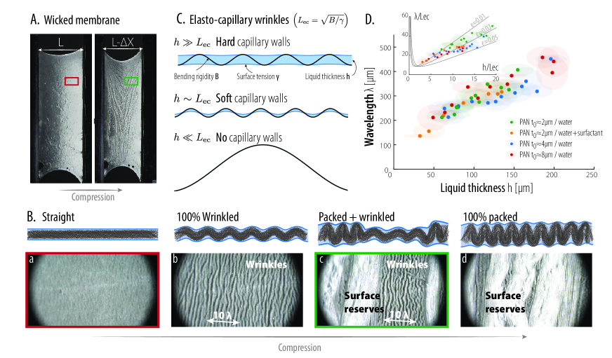
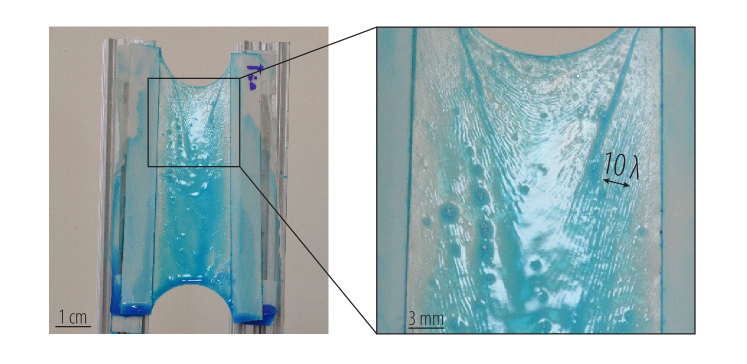
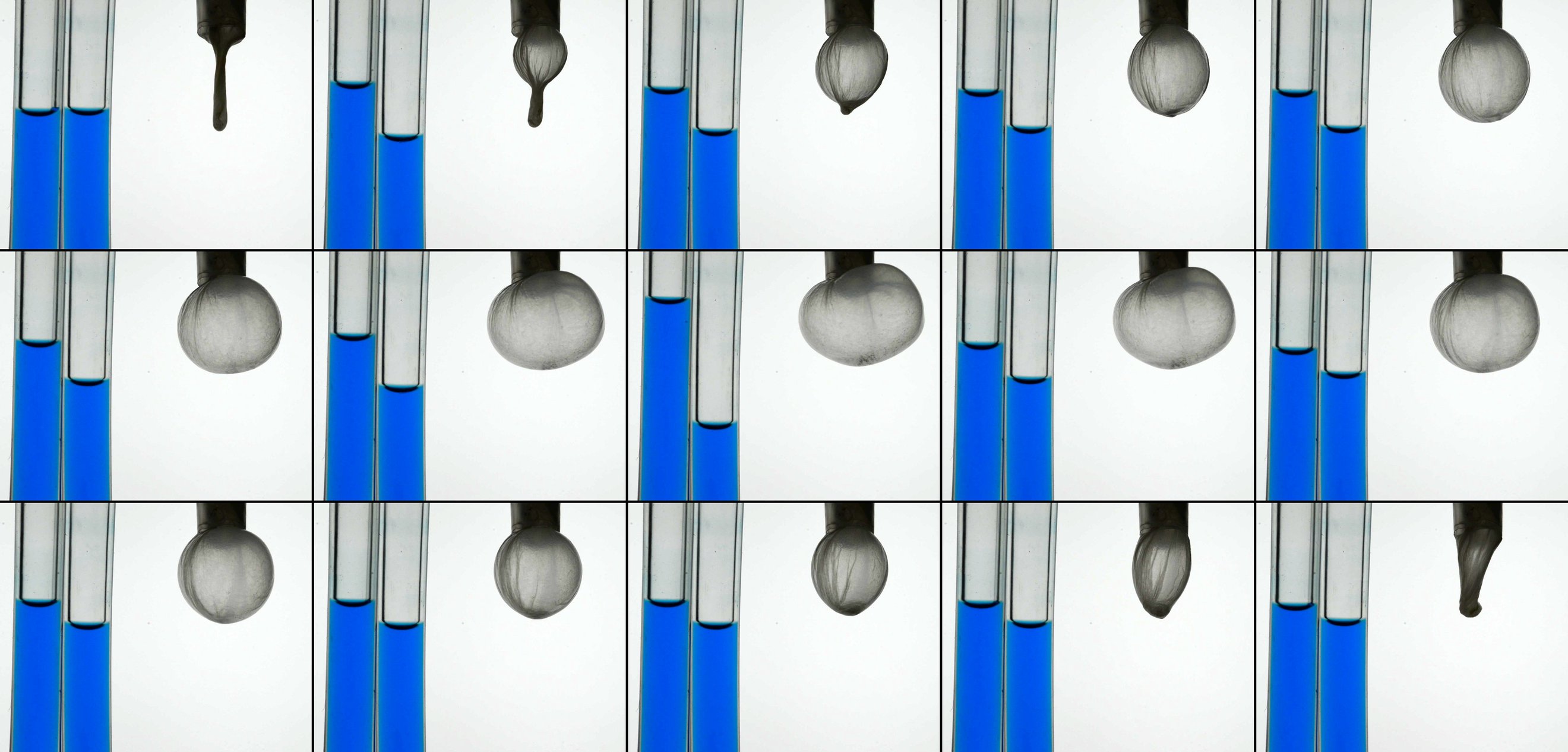
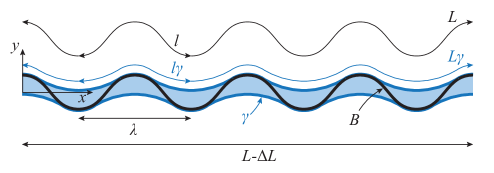
To shed light over the mechanics of membrane reserve self-assembly, we now investigate the behavior of the wicked membrane at the microstructural level, i.e. at lengthscales of the order of the liquid film thickness. Figure 2 reports typical global and close-up views of a membrane undergoing compression. It is readily seen that whenever compression starts, the initially flat membrane (Fig. 2A left and Fig. 2Ba) is rapidly textured with a wrinkling pattern exhibiting a clear wavelength (Fig. 2A right and Fig. 2Bb). Wrinkling is a trademark of thin elastic sheets, and develops spontaneously in a variety of contexts: pinched skin, shriveling fruits [Cerda2003], brain sulci [Tallinen2016], hanging curtains [Vandeparre2011] or more generally thin sheets under tension [Davidovitch2011]. This elastic instability occurs whenever a compressed slender structure is bound to a substrate resisting deformation. The emerging wavelength of this particular form of buckling therefore results from a trade-off between the deformation of the membrane and that of the substrate in order to minimize global energy. Here, the substrate role is played by the liquid film interfaces, which can be seen as soft capillary walls restraining the deformation of the membrane. Interestingly, experiments reveal that the wrinkles wavelength is neither particularly sensitive to the value of interfacial tension nor the fibrous membrane thickness , but scales linearly with the liquid film thickness , here measured by means of colorimetry (see Fig. 2D and Materials & Methods). In order to further grasp the physics of wrinkle formation, we develop a simple model where a periodic sinusoidal membrane of bending stiffness per unit depth exhibiting a wavelength interacts with a liquid film exposing two free surfaces of surface tension , see Fig. 2B.
Under the constraint of constant liquid film volume and imposed compression , we minimize the total energy of the system, consisting of the membrane elastic energy and the surface energy , with and denoting respectively the local membrane curvature and the exposed surface of the liquid film per unit depth (see details in Supplementary Material). The model reveals as the relevant parameter governing the behavior of the system, with being the elastocapillary length [Roman2010]. The limit typically corresponds to the behavior of everyday life soaked fibrous membranes (e.g. wet paper or cloth), that just sag or buckle globally when compressed, irrespective of any surface tension effects (see Fig. 2C). Conversely, our experiment is characterized by values of for which the microstructure differs markedly from the previous one: interface energies cannot longer be neglected and the membrane now buckles under the capillary confinement of the interfaces (see Fig. 2C). Indeed, in this regime the ratio of the surface energy to the elastic energy scales as , i.e. any deformation of the liquid surface introduces a strong energetical penalty, making it clear that in-film wrinkling is a low energy state configuration. This phenomenon is therefore reminiscent of buckling under rigid confinement, for which wavelengths also scale linearly with the confinement gap for a given compression [Roman1999], and this behavior is indeed nicely recovered by our model (see inset of Fig. 2D). Somewhat surprisingly, the experimentally measured wavelengths prove to be insensitive to the compression. This behavior, not captured by the model, coincides with the emergence of a second, tightly packed, accordion-like phase (see Fig. 2B). This second phase, in mechanical equilibrium with the wrinkled phase, has a high membrane storage capacity and actually corresponds to the membrane reserve. The coexistence between these phases allows to continuously transfer material from one phase to another, and warrants the effectiveness of the wicked membrane as a stretchable material.
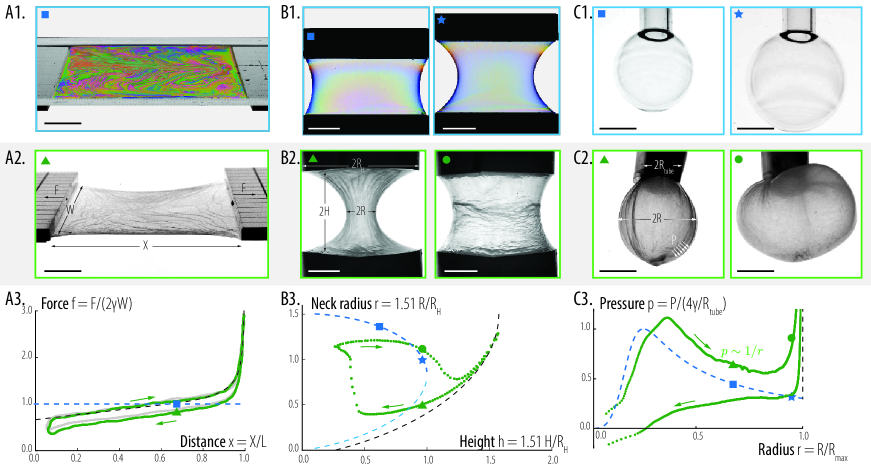
The local mechanics just described reflects into global geometries and force response that we explore next in Figure 3. There we subject wicked membranes to three different elementary solicitations, corresponding to stretching of planar-, cylindrically-, and spherically-shaped membranes. Strikingly enough, the equilibrium shape adopted by the wicked membrane in each configuration strongly resembles that of a liquid film under the same conditions: planar film, catenoid and bubble. Once again, this behavior is made transparent by realizing that in the limit the energy of the wicked membrane is dominated by its capillary contribution; the equilibrium shapes therefore essentially correspond to minimal surfaces. Although they differ strongly in longevity, ways of fabrication and internal structure, the wicked membranes and liquid films therefore present interesting similarities. Upon closer inspection though, the shapes of the membranes appear to differ from their liquid counterparts in some respects. For example, a planar membrane attached on only two straight edges adopts a stable shape (Fig. 3A), whilst a liquid film in the same configuration would merely burst. To understand this stabilization mechanism for membranes, we have to perceive that some regions of the membrane may undergo stretching up to a point where the membrane reserves are fully exhausted. Pure stretching deformations represent a far higher energetical cost as compared to bending ones [Audoly2010] and as a first approximation, this sharp energetical penalty can be seen as an inextensibility constraint. And indeed, the shapes adopted by the planar configuration can fully be captured with a surface area minimization under isoperimetric constraint (see Supplementary Material). This mixed liquid-solid behavior allows to stabilize the catenoid shape beyond its classic point of bursting to unveil new equilibria (Fig. 3B and Supplementary Material), and is also responsible for significant deviations from Laplace’s law in the bubble configuration (Fig. 3C). Such a hybrid mechanical behavior is again reminiscent of the response of cellular membranes, and indeed, whether for lymphocytes, fibroblasts [Guillou2016, Groulx2006] or wicked membranes (Fig. 3), the mechanical response switches from liquid-like to solid-like once all the membrane reserves have been flattened out.
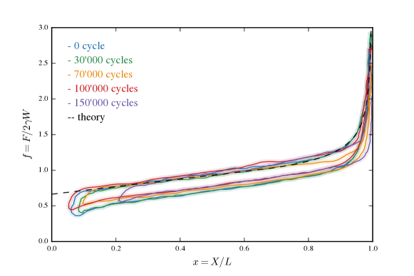
The peculiar behavior of our wicked membrane stems from its compound nature: while surface tension allows it to undergo ample shape changes, its solid underlying matrix provides mechanical robustness. Geometrical reorganizations at the microstructural level (reserve self-assembly or unfolding) are key in the mechanics of the wicked membrane, and allow in particular to prevent any significant stretching at the molecular level. This results in a marked resilience of this material to fatigue, as illustrated by the unvarying mechanical response of the membrane after more than 100,000 cycles of 10-fold stretching and compression events (Fig. 3A3 and Supplementary Materials).
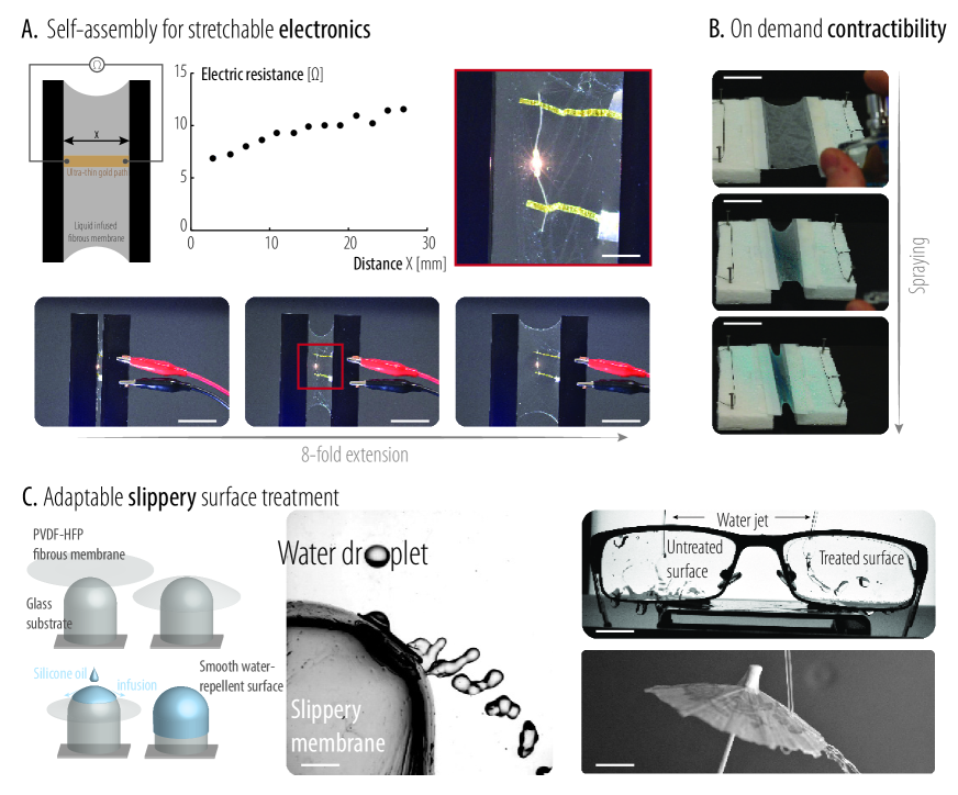
Moreover, it is worth emphasizing that the mechanical functionalization of a membrane into a highly stretchable membrane only relies on a combination of elasticity, capillarity and geometry. As such, the process is widely universal (see the list of tested polymers in the Supplementary Material), and opens appealing prospects from an engineering point of view. To illustrate but a few applications taking advantage of this mechanical function, we present some proofs of concepts in Figure 4. First we demonstrate that affixing submicronic thick golden paths to the membrane allows to effortlessly obtain a 10-fold stretchable conductive material, presenting an unusual reversibility. Interestingly, due to the formation of folds and membrane reserves, the effective electrical resistance of the material displays a dependence to its stretching state (Fig. 4A). Second, by controlling the formation of the liquid film (via the surrounding humidity level, or with the instant release of a liquid), on-demand contractility of the wicked membrane is instantaneously obtained, making it straightforward to apply forces, possibly while distorting the membrane (Fig. 4B). Finally we show that a wicked membrane infused with a lubricant becomes a transparent slippery surface [Okada2014] that can provide an instant non-wetting functionalization to curved, rough, warped and deformable surfaces thanks to its exceptional shape adaptability (Fig. 4C).
The use of membrane reserves to fuel large shape changes is encountered in an extremely wide variety of animal cells, but this strategy has so far not been used to create stretchable synthetic materials. The ease of manufacturing, self-assembly of membrane reserves, universality of the process along with its robustness opens tremendous novel pathways for the design of synthetic stretchable devices (possibly biocompatible), electronics, batteries or actuators.
References
Materials
The polymers used to fabricate the fibrous membranes are Poly(vinylidene fluoride-co-hexafluoropropylene) (PVDF-HFP, Solvay), Polyacrylonitrile (PAN, M.W. 150,000, Sigma Aldrich), Polycaprolactone (PCL, M.W. 80,000, Sigma Aldrich) and Polyvinylpyrrolidone (PVP, M.W. 1,300,000, Acros Organic). The solvents are n,n-dimethylformamide (DMF, Carlo Erba Reagents) and ethanol (absolute, Sigma Aldrich). The liquids used to infuse the fibrous membranes are deionized water, glycerol (Sigma Aldrich), ethanol (absolute, Sigma Aldrich) and PDMS v100 oil (Sigma Aldrich). The concentration of polymer of each polymer/solvent solution is 10% wt. A summary of the constituents is provided in Table 1. Surface tensions of the liquids are characterized using a Krüss K6 manual tensiometer (hanging ring). Erioglaucine disodium salt (Sigma Aldrich) is used to dye the fibrous membrane (dissolution of the coloring agent in the polymer/solvent solution prior to electrospinning) and the infusing liquids. 1mm wide gold strips are obtained by manually cutting 100 nm thick edible gold leaves (purchased from Alice Delice) using a surgical blade.
| Polymer | Solvent | Wicking liquid |
|---|---|---|
| PAN | DMF | water - glycerol - ethanol - silicone oil |
| PVDF-HFP | DMF | ethanol - silicone oil |
| PCL | DMF | ethanol - silicone oil |
| PVP | ethanol | silicone oil |
Sample preparation
The fibrous membranes are obtained using an electrospinning technique [Greiner:2007] using the electrospinning apparatus ES-1A (Electrospinz Ltd.) following these key steps:
-
1.
A polymer is dissolved in a solvent (the polymers and corresponding solvents that are used in this work are presented in Table 1).
-
2.
The solution is injected through an electrically charged blunt needle (diameter of the needle 1mm at a rate of 0.02 ml/min, between 10 and 15kV). The outgoing droplet is instantaneously destabilized through the formation of a Taylor cone which is ejected as a liquid rod towards an electrically neutral fixed plane target (distance between the tip of the needle and the target: 17cm). As it travels towards the target, the solvent evaporates from the liquid rod which therefore quickly undergoes a swirling instability randomly deviating it.
-
3.
The resulting fibrous mat (made of the addition of solid fibers continuously generated) is recovered from the target, which was previously covered with anti-adhesive cooking paper (purchased from Monoprix S.A.) to avoid sticking.
Once the membrane is attached to the mobile supports (Thorlabs translational elements or laser cut PMMA assembly of 8 translational supports), it is wicked by a wetting liquid (see Table 1) using a Terumo 10ml syringe or a spray. Upon compression, the surface reserves are instantaneously formed through the wrinkling and folding of the membrane under the capillary forces.
Thickness characterization of the infusing liquid film
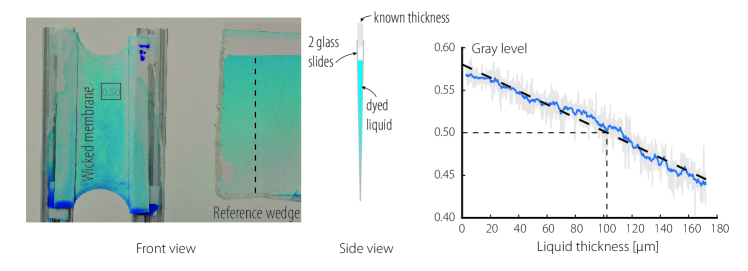
For the study the wrinkling wavelength as a function of the liquid thickness , a colorimetry tool is used to characterize the liquid film thickness. The membrane is wicked by a dyed liquid (water dyed blue) and a photograph of the infused membrane is taken next to a calibration wedge containing the same dyed liquid with a D810 Nikon camera. Comparing the photograph’s local gray value on the membrane and the thickness versus the gray value curve (see figure 5), we can locally estimate the thickness of the liquid film. Image analysis is performed using the image processing package Fiji.
Wavelength measurement
The wrinkling wavelength is measured when the wicked membrane is slightly compressed. The membrane is illuminated from the side in order to enhance the wrinkles’ contrast and a photograph is taken with a D810 Nikon Camera. For each liquid film thickness (different amount of wicked liquid), a set of 4 wavelength measurements is performed. The coloring agent (erioglaucine disodium salt) did not show to change the liquid surface tension significantly. A typical wavelength measurement image is presented in figure 6.
Force measurement and fatigue characterization
The force versus displacement curve of the plane wicked membrane is performed using a cantilever beam method on a silicone oil infused PVDF-HFP fibrous membrane. The cantilever beam’s mechanical response was calibrated using calibrated weights (weighed with a Mettler-Toledo MS 0.01 mg precision scale). The membrane is supported by two floating rafts on a water bath to ensure frictionless translational supports. The presented extension/compression force measurement cycles are performed at around 1mm/s but show little sensitivity to displacement speed (the same force vs. displacement curve was obtained for a twice as fast displacement speed).
The fatigue test was performed on a silicone oil infused PVDF-HFP fibrous membrane mounted on a crank rod system and the wicked membrane underwent 3 extension/compression cycles per second. The compression/extension cycle corresponds to an end to end distance X varying from 2 mm to 3.7 cm. The membrane was re-infused by silicone-oil every 20,000 cycles to avoid drying. Small circular holes (hundreds of microns in diameter) appeared at around 60,000 cycles, slowly growing up to 150,000 cycles. At this last point, the holes had a significant impact on the mechanical behavior of the wicked membrane (see fig 7) and the membrane tore off shortly after.
Catenoid neck radius measurement
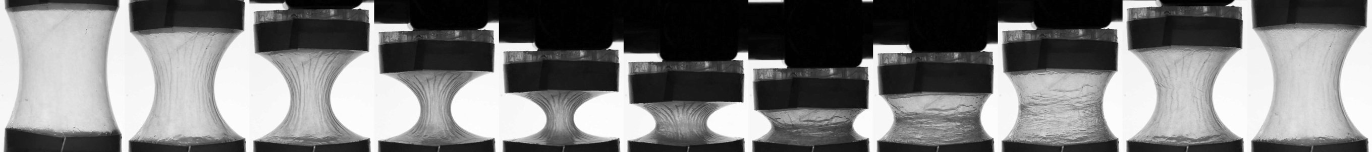
To study the equilibrium forms adopted by a wicked membrane in a cylindrical configuration, a PAN membrane is attached on the edge of two laser cut PMMA discs (diameter cm) with 3M double face tape. The membrane is wicked with deionized water and the distance between the two discs is controlled using a Thorlabs 25 mm manual translation stage. Throughout the compression/extension cycle, the shape adopted by the wicked membrane is filmed with a Nikon D810 camera and image post-processing (Python) allows to gather the neck radii of the resulting catenoid for the visited disc distances. Figure 8 shows a sequence of such compression/extension cycle and makes it clear that the shape adjustments of the wicked membrane are mediated by the self-assembled folds that act as surface reserves.
Wicked membrane bubble pressure measurement
To measure the pressure inside an inflated spherical wicked membrane (PAN fibrous membrane wicked with deionized water), visualization of an adjacent ethanol filled tube is used. The bubble is inflated with air using a PHD Ultra Syringe Pumps (Harvard apparatus) at a rate of 6 ml/min. The air-entrance tube is connected to a U-shaped tube partially filled with dyed ethanol with a T-junction. One end of the U-shaped tube is therefore pneumatically linked to the bubble, while the other end is open (at atmospheric pressure). The ifference in height of the two ethanol interfaces inside the U-shaped tube indicates the pressure inside the bubble, knowing its density kg/m3 and earth acceleration m/s2 (). The pressure is normalized by , which is the theoritical maximum pressure for a spherical bubble of surface tension , inflated out of cylindrical tube of radius ( 4.5 mm in our experiment). It is to be mentioned that in contact with the PAN membrane, the surface tension of deionized water drops from 72 to 53 mN/m.
Wavelength
Here, we study the buckling of an elastic beam confined inside a liquid film. Elastic energy minimization would favor high wavelength but for flexible enough beams, capillary interface energy of the liquid film can become non-negligible; the system will find a trade-off wavelength, minimizing the sum of the elastic and capillary energies.
The solid beam is described by whereas the liquid/air + solid/air interface is given by . Indeed, since the liquid/air and solid/air interface specific energies are considered to be the same, corresponds to the liquid/air interface where the beam is covered by liquid, but is given by the beam surface where no liquid covers the beam.
Energies
Because the wavelength is much smaller than the total beam length , boundary conditions at the ends of the beam are not considered. The elastic and interface energies respectively are given by and :
| (1) |
| (2) |
where represents the beam curvature and represents the bottom liquid/air+solid/air interface. The factor in eq. (2) comes from top/down pseudo-symmetry (the bottom interface has the same length as the top interface).
Volume conservation
Incompressibility of the liquid requires for the volume to be conserved:
| (3) |
Inextensibility constraint
Inextensibility of the beam provides a constraint on its length:
| (4) |
Refocusing the problem on one wavelength
Normalizing
Interface
The liquid interface and the elastic beam merge at the x-coordinate (see figure 11). Because where no liquid covers the beam, has to satisfy the adapted formulation of equation (13) (volume conservation):
| (15) |
We abandoned the ”” notation for clarity.
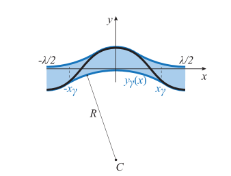
Since pressure has to be constant inside the liquid film, is defined as a circular arc between and (of radius ). We assume continuity between the liquid interface and the beam at the triple point (no penetration of the beam across the liquid interface) :
| (16) |
and a tangent connection between the liquid surface and the beam (the liquid wets the beam perfectly):
| (17) |
These two conditions provide an explicit formulation for :
| (18) |
where , the y-coordinate of the center of the circle describing the liquid interface, is given by:
| (19) |
and the radius of said circle is expressed as followed:
| (20) |
A schematic representation of the liquid surface is presented in figure 11.
Summary
The goal is to find the wavelength which minimizes the total energy (elastic + capillary) given by :
| (21) |
where the constant factor of eqs. (11) and (12) is discarded because it does not affect the minimization.
The inextensibility constraint on the beam reads:
| (22) |
and the volume conservation is given by:
| (23) |
The liquid surface is derived in section Interface Interface .
The unknowns of the problem are , and .
Energy minimization for a sinusoidal buckling pattern
In order to simplify the problem, we restrict ourselves to sinusoidal buckling patterns of wavelength for the elastic beam, i.e. . These are the energy minimization steps that were followed:
-
1.
Choose a guess wavelength (we define ). The guess beam buckling pattern is given by .
-
2.
The amplitude of the sinusoid is constrained by the inextensibility constraint. It can be found by numerically solving eq. (22) ( is known):
(24) -
3.
Next, we find that satisfies the volume conversation constraint given by eq. (23) ( is known). The integration is performed using a guess value for and using eq. (18):
(25) where and are given by eqs. (19) and (20) respectively:
(26) and the radius of said circle is expressed as followed:
(27) It is to be mentioned that is described by the expression in eq. (25) for but as the beam surface where .
-
4.
We now have to compute the total energy of the system using equation (21) where is described as explained in the previous step. The curvature is defined as . Note that this energy only depends on the first guess value .
-
5.
Iterative steps are performed to find the wavelength that minimizes the total energy of the system.
Considering a non-zero thickness of a porous beam
Experimentally, the wrinkling wicked membrane has a non-zero thickness. The thickness of the beam can be taken into account in our model by considering a vertical shift of half a thickness of the liquid interface. Since the membrane is very porous and entirely wicked by the liquid, we consider the that the entire thickness of the beam adds up to the total liquid volume . Step 3 of the previous section therefore has to be revisited. is shifted as follows:
| (28) |
where is the thickness of the porous beam. The volume constraint equation given in eq. (29) rewrites as:
| (29) |
It is to be noted that this formulation is only valid for small deformations (i.e. small compressions ). In this study, we consider the membrane to grow as the liquid film gets thicker, i.e. the membrane thickness is proportional to the liquid film thickness wicking it (we use ). However, we do not consider the bending stiffness per unit depth to change during this growth.
Graphical results and discussion
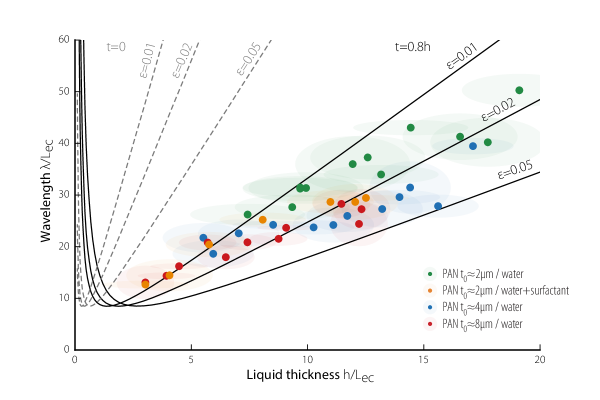
Figure 12 presents the dimensionless wavelength versus the dimensionless liquid thickness for PAN fibrous membranes of different thicknesses wicked by different liquids. Both and are normlized by the elastocapillary length . The surface tension was measured with the Krüss K6 manual tensiometer (deionized water showed a drop in surface tension when previously put in contact with a PAN membrane, from 72 mN/m to 53 mN/m). To test the dependence of surface tension on the wavelength, the experience was performed with deionized water and a water/soap solution (of measured surface tension 30 mN/m). The membrane bending rigidity per unit depth being low, it could not be measured experimentally. Therefore, it was roughly estimated as where is the membrane dry thickness, the typical radius of the fiber composing the membrane ( m) and is the PAN Young’s modulus ( GPa). Finally, is a dimensionless parameter to account for the membrane porosity (here adjusted to the experiments using ).
Plane wicked membrane
Here we consider a wicked fibrous membrane of width attached to two parallel rigid straight supports at an initial rest distance from one and other. Upon compression (varying the distance between the two supports) the membrane remains under tension due to the liquid surface tension and stores the excess membrane inside wrinkles and folds which can afterwards be recruited when extended. The force necessary to keep the two poles at a distance is here analyzed depending on , and the surface tension .
Unlike a soapy liquid film on a rigid frame, our membrane is only attached on two edges and has two free edges. It is to be mentioned that a soapy liquid film would break off immediately if it was only “attached” on two of its edges. In order to minimize its interface energy with air, the wicked membrane adapts its shape and this minimization with isoperimetric constraint spontaneously leads to circular arcs of arc length on its free edges [Berest:1998]. Indeed,
the the membrane can wrinkle and fold but cannot be stretched.
Early compression:
At early compression, assuming the free edge describes a circular arc of length and that the two supports are at a distance , we include two new variables and , respectively the radius and angle span of the circular arc which are presented in figure 13.
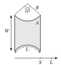
and are related to and through two equations:
| (30) |
| (31) |
The surface area of the liquid infused membrane then writes:
| (32) |
And the normalized force () that an operator has to apply on the rigid edges to ensure a distance is given by the derivative of the energy with respect to :
| (33) |
which can be solved numerically.
Advanced compression:
At a more advanced compression, when reaches (i.e. when becomes smaller than ), the geometry adopted by the liquid infused membrane changes and a sketch of it is presented in figure 14. The radius of the circular arc remains of interest and a new variable is considered, it represents the length on which the membrane is sticked to the support.
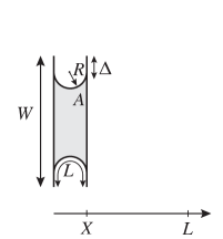
and are given by the 2 relations:
| (34) |
| (35) |
and again, the surface is calculated:
| (36) |
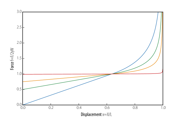
Finally, injecting the three previous relations in the force equation, eq. (33), leads to an explicit expression for the force:
| (37) |
where x=X/L. The theoretical dimensionless force vs. displacement curves are given in figure 15 for 4 different rest distance to width ratios L/W.
Catenoid formed by the wicked membrane
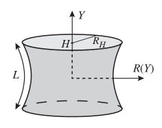
Here, we consider a cylindrical geometry, reminiscent of the archetypical liquid soap catenoid : the wicked membrane is attached to two rigid parallel rings of radius at an initial distance . Since the membrane is infused with a liquid, the output shape will minimize the total interfacial energy of the system, i.e. where is the liquid-vapor specific energy of the liquid, and the surface area of the catenoid. As surface tension does not vary, the system seeks to minimize its surface area S given by:
| (38) |
Moreover, since the fibers of the membrane are inextensible (they can wrinkle inside the liquid film, but cannot be stretched) an inextensibility constraint is to be applied for the outer length of a given fiber from to , this length is given by [Berest:1998]:
| (39) |
where is the rest length between the two rings (corresponding to the distance between the two rings when the membrane is perfectly cylindrical). The energy of the system can then be re-written as :
| (40) |
Where is the Lagrange multiplier corresponding to the constraint given in eq. (39). The inextensibibilty constraint is not active when . Since does not depend explicitly on , minimizing can be done by solving :
| (41) |
Where c is a constant to be determined. Deriving the equation leads to:
| (42) |
Which, after solving, leads to :
| (43) |
With two implicit equations for and :
| (44) |
| (45) |
which have no explicit solutions but can be solved numerically.
When the inextensibility constraint becomes inactive and as for the usual liquid catenoid, only the surface area given in eq. (38) has to be minimized.
The catenoids can be compared by analyzing their neck radii as a function of the distance between the two rings for given rest lengths between the rings (distance between the rings for which the membrane is perfectly cylindrical).
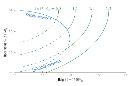
It is to be mentioned that a wicked membrane can display two stable catenoid shapes for given parameters. For example, the curve corresponding to shows that for a given height slightly below 1.0, the neck radius can be that of a pure soapy liquid catenoid (blue curve), or that of a catenoid with isoperimetric constraint () corresponding to the green curve. This bistability results in a strong path-dependence for the adopted shape of the catenoid. Indeed, when this catenoid comes from , it follows the green curve when bringing the two rings closer (i.e. , the isoperimetric constraint is active). When it crosses the unstable liquid catenoid solution (dotted blue line), changes sign and becomes negative, thus making the isoperimetric constraint inactive. The catenoid then jumps to the stable liquid catenoid solution (solid blue curve). On its way back (increasing ) it continues traveling only on the blue curve until it crosses the axis, in which case it will jump back to the isoperimetric constrained solution (green curve).