Dopamine modulation via memristive schematic
Abstract
In this technical report we present novel results of the dopamine neuromodulation inspired modulation of a polyaniline (PANI) memristive device excitatory learning STDP. Results presented in this work are of two experiments setup computer simulation and physical prototype experiments. We present physical prototype of inhibitory learning or iSTDP as well as the results of iSTDP learning.
keywords:
neuromodulation, inhibition, memristive device, dopamine, neuromorphic computing, affective computing, artificial intelligence1 The experimental setup
1.1 Block diagram

The block diagram is presented in the Figure 1 and is the memristive electronic implementation of an excitatory, inhibitory, neuromodulationary artificial neuron. There are three parts of the block diagram represented in colors: excitatory – orange, inhibitory – blue, modulatory – green. Inputs are depicted as triangles. The excitatory learning is implemented via and feedback loops of excitatory memristive device (), where LTP (long term potentiation) blocks implement the learning function above axis and LTD (long term depression) blocks implement learning function below . and implement dendrite spikes. The inhibitory part has different structure, where the LTP is implemented as feedback loop block that uses inbound pre-synaptic signals and outbound of memristive device signals. The LTD is implemented as feedback from neuron outbound signal. The LTP and the LTD implement learning function described in Hennequin et al., (2017) indicated as iSTDP graph in Figure 1. Modulatory blocks influence LTP and LTD functional blocks modulating the amplitude of learning impulses. and are the implementation of a neuronal soma and axon hillock that integrates excitatory and inhibitory inbound signals and generates the outbound signal.
1.2 Wiring schematic

The Figure 2 represents the wiring schematic, where excitatory and inhibitory learning impulses are transmitted to memristive elements. Instead of the generator post-synaptic signals from Figure 1 we used an external generator for simplicity of modeling. The Hebbian STDP is implemented via op-amps and the iSTDP – via op-amps , , . Signals from pre-synaptic spike generator input are transmitted to integrators implemented via op-amp , which set the impulse descending edge of the learning function. The pulse-rise time constant of the integrating circuit is . When the accumulated voltage on the memristive elements exceeds the threshold, the one short multivibrator implemented via the operational amplifier provides a single short pulse, which duration is determined by . Output signals from multivibrator are transmitted to the inverting adder implemented via . Similarly, post-synaptic pulses from input are created via on op-amps , and and then inverted via the op-amp . Output signals from both integrators are transmitted to the adder-integrator op-amp from which transmitted to inhibitory output . Signals from integrators and also are transmitted to the adder implemented via op-amp and later transmitted to the controlled inverter the op-amp . When the non-inverting input of the operational amplifier the op-amp is shorted to the ground, the operational amplifier works as an inverter; otherwise, it acts as a normal amplifier. Output positive pulse from is applied to the key that controls a state of not inverting input of the controlled inverter of op-amp . From the output integrator on the op-amp the signal is transmitted to excitatory output. The modulation of Hebbian STDP is preformed by op-amps and . The function of the”bell” form is implemented on the alternative output ”Sombrero”. The physical implementation of the wiring schematic is depicted in Figure 3.

2 Results
2.1 Simulation

The simulation results are presented in Figure 4. The top graph depicts the level of the dopamine (DA) and identifies the level of modulation of learning impulses that is visible as the increment of green graph amplitude in the bottom graph, that in its turn influences the memristive device conductivity, described below. In the middle the lilac graph represents the result of the memristive device learning the overall conductivity. It is set by modulated learning impulses that are formed as Hebbian learning: where is the time lag between pre-synaptic spike and post-synaptic spike or inbound and outbound impulses. Pre-synaptic and post-synaptic spikes are presented in the Figure 2 as generators and . For the simplification of the simulation purposes we used 2 different generators with phase shift to simulate different s. This way we could depict whole Hebbian learning in one graph. Learning impulses are presented as bottom green graph in the Figure 4.
2.2 Physical implementation
Firstly we have implemented the learning functions for excitatory and inhibitory synapses, results are presented in the Figure 5 left is Hebbian STDP, right one is iSTDP as it was described in Hennequin et al., (2017) and presented in Figure 1.
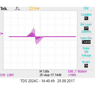
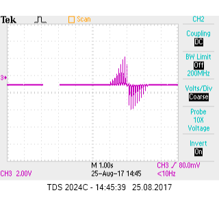
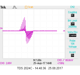
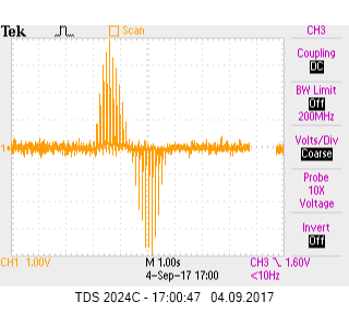
Second series of experiments was dedicated to the re-implementation of DA modulation of excitatory synapses STDP described in Gurney et al., (2015). We have re-implemented biologically inspired modulatory function of DA. Results are depicted in the Figure 6, DA modulation is implemented as potentiometer presented in the Figure 2. The top-left graph depicts learning impulses modulated with minimal level of DA potentiometer , top-right is modulated by DA potentiometer , bottom-left – , bottom-right – . The amplitude of learning impulses increases along with the modulation via DA potentiometer.
Third series of experiments implements the DA modulation of iSTDP, that we assume should be similar to the DA modulation of STDP Gurney et al., (2015), and this is just our assumption at the moment, as we could not find medical literature describing the DA modulation of inhibitory (GABA) synapses and requires further research. The top-left graph represents the iSTDP under influence of minimal DA modulatory potentiometer setup , top-right – , bottom-left – and bottom-right – . Again we indicate the increase of modulated amplitude of learning impulses along with increase of DA modulatory influence.


References
- Gurney et al., (2015) Gurney, K. N., Humphries, M. D., and Redgrave, P. (2015). A New Framework for Cortico-Striatal Plasticity: Behavioural Theory Meets In Vitro Data at the Reinforcement-Action Interface. PLoS Biology, 13(1):e1002034.
- Hennequin et al., (2017) Hennequin, G., Agnes, E. J., and Vogels, T. P. (2017). Inhibitory Plasticity: Balance, Control, and Codependence. Annual Review of Neuroscience, 40(1).
- Vogels et al., (2013) Vogels, T. P., Froemke, R. C., Doyon, N., Gilson, M., Haas, J. S., Liu, R., Maffei, A., Miller, P., Wierenga, C., Woodin, M. A., Zenke, F., and Sprekeler, H. (2013). Inhibitory synaptic plasticity: spike timing-dependence and putative network function. Frontiers in Neural Circuits, 7:119.