Exploring matter wave scattering by means of the phase diagram
Abstract
For matter wave scattering from passive quantum obstacles, we propose a phase diagram in terms of phase and modulus of scattering coefficients to explore all possible directional scattering patterns. In the phase diagram, we can not only have the physical bounds on scattering coefficients for all channels, but also indicate the competitions among absorption, extinction, and scattering cross sessions. With help of this phase diagram, we discuss different scenarios to steer scattering probability distribution, through the interference between - and -channels. In particular, we reveal the required conditions to implement a quantum scatterer, i.e., a quantum dot in semiconductor matrix, with a minimum (or zero) value in the scattering probability toward any direction. Our results provide a guideline in designing quantum scatterers with controlling and sensing matter waves.
I Introduction
A deep understanding on the wave scattering in passive obstacles plays a crucial role in nanophotonics, with a variety of practical applications from nanoantenna, metasurface, sensor, imaging system, to light harvesting science1 ; nature1 . Exotic scattering phenomena at the subwavelength scale have been revealed such as coherent perfect absorbers, superscatterers, invisible cloaks, directional radiation scatterers, and superabsorbers absorber ; superscattering ; cloak ; kerker ; forwardexp ; backwardexp ; superabsorber . To have a universal picture on all the allowable scattering coefficients, we apply the concept of energy conservation law to absorption cross section, resulting in a phase diagram for electromagnetic waves phase . Regardless of details on the geometric configurations and material properties, physical boundary and limitation for zero backward/forward scatterings can be easily illustrated in the phase diagram kerker1 .
Similar to the classical counterpart, discussions on quantum particles encountering collisions have been an extensive research subject with different physical disciplines. For ultracold atoms of 87Rb, the Fano-signature interference in quantum scattering, between resonant -wave to the background -wave, was observed experimentally image1 ; image2 . Through the classical-quantum correspondences between optical and matter waves, the concept for invisible claoking has been applied to quantum scatterers formed by spherical quantum dots in core-shell heterostructures qcloak1 ; qcloak2 ; thermoelectric ; qcloak4 . Moreover, it was realized that even though the electron dynamics in graphene is governed by the relativistic massless Dirac equation, the approach to deal with the related scattering problem of electronic transport in graphen is similar to that used in electromagnetic Mie theory qcloak3 ; graphene1 ; graphene2 . Under the scattering picture, Klein tunneling, with a complete suppression in the backward direction, can be transformed as an isotropic scattering process with spin-orbital interactions graphene3 .
To design quantum resonant scatterers at subwavelength scale, detailed physical quantities, such as effective mass and potential of a quantum particle, have been taken into account through higher-oder expansions resonant . Nevertheless, a systematic way to have all possible scattering states from quantum matter waves, irrespective of configuration in a scattering system, is still lack. In this work, we consider the inelastic scattering from quantum matter waves, based on Schrödinger equation. In terms of the phase and modulus of scattering coefficients for passive quantum obstacles, we propose a phase digram to provide complete information among extinction, absorption and scattering cross sections. With probability conservation, i.e., the unitary relation, we discuss directional scatterings of matter waves by means of the phase diagram. Unlike the electromagnetic counterpart kerker , a perfect zero forward scattering can be achieved in quantum particles through the interference between - and -waves when they have the same phases and modulus. Moreover, a systematic way to realize scattering matter wave with a reduced scattering probability at any arbitrary direction is also demonstrated. Our results provide the guideline to design directional quantum scatterer with matter waves.
II Phase diagram for quantum scattering matter waves
For a quantum particle with energy and momentum along the -direction, in absence of a finite-ranged obstacle, the unbounded stationary eigen-states can be described by a plane wave, , with the corresponding wavevector . Even though the introduction of a quantum obstacle may alter the original eigen-states, the corresponding eigen-energy remains unchanged in the elastic process. Then, one can apply the Lippmann-Schwinger equation to construct the new scattered state for a finite-ranged obstacle in an arbitrary shape jj .
Furthermore, if the scattering obstacle possess rotational invariance, the Hamiltonian for the quantum matter wave commutes with angular momentum operators, i.e., and , corresponding to the total and -component angular momentum operators, respectively. With this symmetry, we can apply the partial wave formalism to matter wave scattering problem. In the asymptotic region, one can write down the wave function for quantum obstacle as book1
| (1) |
Here, we have incident matter wave as a plane wave, and the corresponding scattering amplitude can be defined as
| (2) |
with the scattering coefficient , the Legendre polynomial , and the index in angular momentum channels labeled as . It is noted that a monopole () is also called as -wave; while a dipole () is called as -wave. From the asymptotic result shown in Eq.(1), by integrating probability flux along the radial component over a closed area, we can directly find the corresponding absorption (also called as the reaction), scattering, and extinction cross sections, respectively,
| (3) | |||||
| (4) | |||||
| (5) |
One can see that in these convergent series, the dominant terms are often determined by environment size parameters, i.e., with the effective range of scatterer radius qcloak1 ; qcloak2 ; qcloak3 . We want to remark that through the optical theorem, the extinction cross section is also linked to the scattering amplitude in the forward direction jj . In addition, an alternative method to calculate the cross section is using the phase shift , by re-defining the scattering coefficient as book1 .
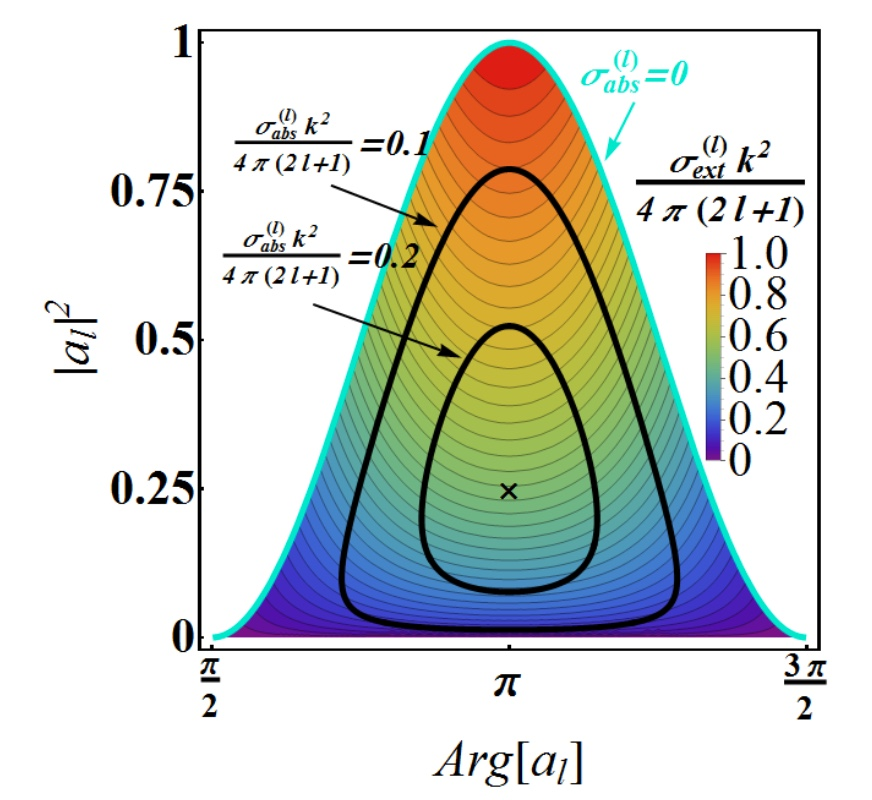
With probability conservation, i.e., the unitary relation, one can deduce that (or ) for each angular momentum channel. Here, is the partial absorption cross section for the -th channel, defined as . Then, one can see that the unitary relation guarantees a real value for phase shift, . On the contrary, if some incident quantum particles are annihilated by scattering obstacles or lose their energy, we have for a non-zero absorption cross section. Next, we introduce a phasor representation for the scattering coefficients, by writing , into this inequality . As a result, a phase diagram for every partial extinction cross section emerges naturally, as shown in Fig. 1, defined by the phase and modulus of scattering coefficient , in each angular momentum channel labeled by the index . Here, we note that in this phase diagram, the vertical axis gives the strength in the scattering channel; while the horizontal axis reflects the phase in scattering coefficient. Moreover, colored region reveals all the allowable solutions for a passive quantum obstacle, i.e., ; while the uncolored (or in white-color) regions correspond to unallowable solutions. The range for allowable solutions is for phase, and for modulus. Moreover, between the colored and uncolored regions, the boundary is depicted by a trajectory in light-blue-color, which exactly follows the unitary relation.
In addition to the allowable solutions for scattering coefficients, in a single phase diagram, one can also display information among the normalized absorption, scattering , and extinction cross sections, defined as , , and , respectively. As shown in Fig. 1, the value of normalized extinction cross section is depicted in the contour-plot, which is bounded within . Then, we also give two sets of constant absorption cross section in black-colors, and , respectively. These black-curves reveal non-trivial scattering events, with a constant absorption cross section, but totally different extinction and scattering cross sessions. The maximum value in the absorption cross section is , see the black-cross marker, which reflects the resonance condition for a complete cancellation in the out-going spherical matter wave, as or . Exotic scattering phenomena, such as quantum sensors sensor and anti-laser antilaser can also be clearly illustrated in this phase diagram phase . In addition, the common adopted Born approximation to deal with weak scattering, valid for a shallow potential or a small particle size compared to the wavelength in quantum wave, the phase in the scattering coefficient is always or comment1 . Moreover, even though one can introduce a complex potential into Schrödinger equation or impose an imaginary term for the phase shift book1 ; book2 , such a phenomenological approach is beyond the scope of this work.
III Interferences from dominant - and -waves
Although in the first look, this phase diagram for quantum matter waves, shown in Fig. 1, shares the same similarity to that introduced for electromagnetic system, the underline physical interpretations are totally different. In quantum matter wave formalism, the physical measurement for probability is implemented through an ensemble average. Moreover, instead of electric or magnetic dipole excited in electromagnetic waves by subwavelength structures, the two lowest-orders for predominant scattering phenomena in quantum subwavelength system are monopole and dipole, i.e., -wave with and -wave with , respectively.
Now, at the subwavelength scale, we study the differential scattering cross section for a quantum scatterer by calculating
| (6) |
which means the ensemble average in the probability scattered into the angle jj .
In particular, we seek for directional scattering events by asking for the zero probability distribution through the superposition from dominant - and -waves. That corresponds to find a family of solutions for the scattering coefficients and to satisfy the following condition:
| (7) |
or equivalently in the phasor representation:
| (8) |
Here, is defined in the spherical coordinate, which is bounded by . In the regime , the argument of would be ; while when , the argument is .
Instead of trivial solutions, , let us consider the scenario when two scattering coefficients are the same both in their phase and modulus. Then, to satisfy the required condition given in Eq. (7), we have , or equivalently , which reveals a node (zero) in the corresponding probability distribution. It should be remarked that in this scenario, once the phase and modulus for and wave are the same, the system can possess any scattering cross section, as indicated in Fig. 1.
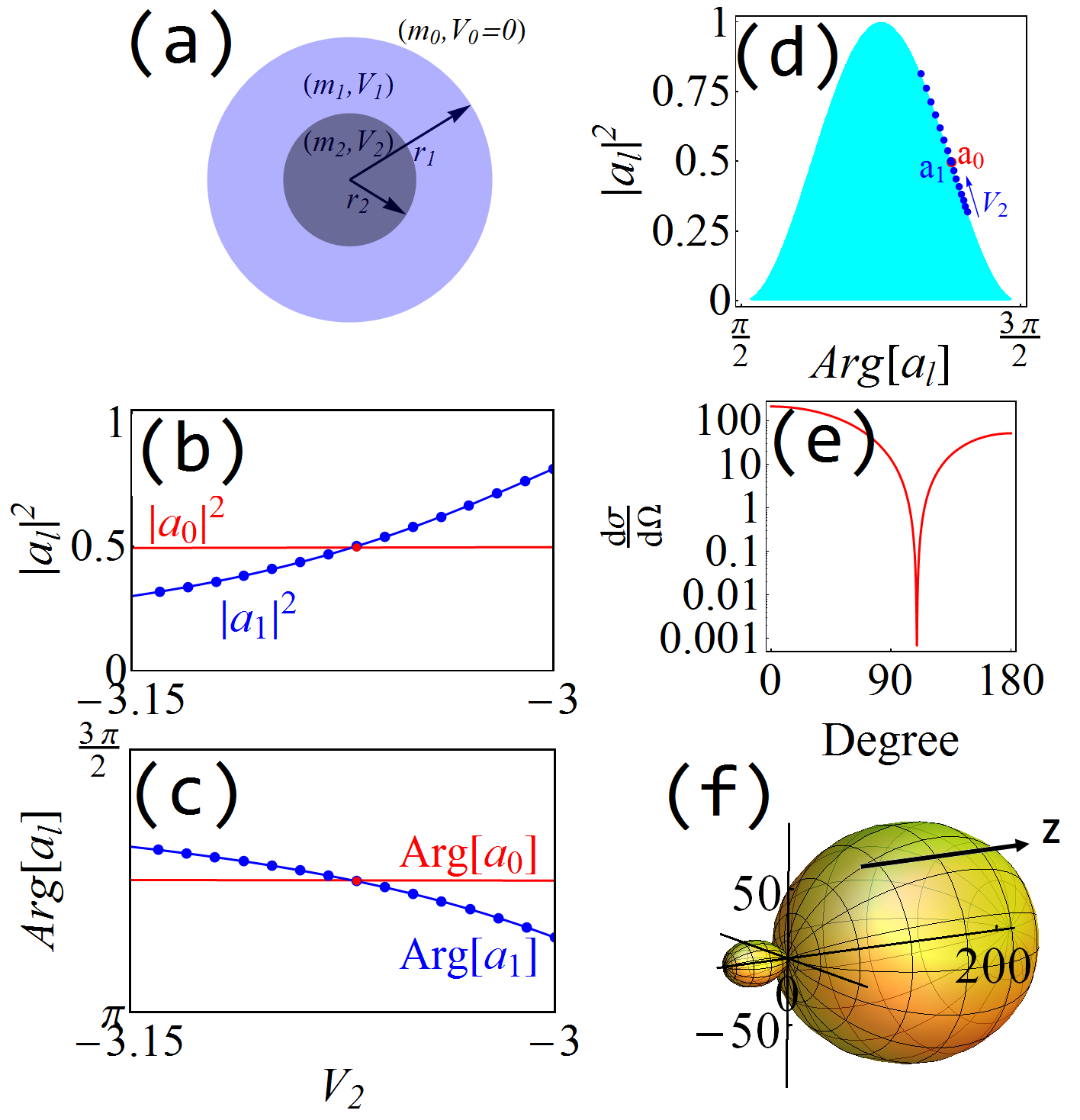
For possible experimental implementation, we consider conducting electrons within a semiconductor matrix encountering an artificial quantum dot as an example. This artificial scatterer is constituted by two concentric spheres, with isotropic, homogeneous effective masses and potentials in the shell and core regions, denoted as (, ) and (, ) as illustrated in Fig. 2 (a), respectively. Effects of edge roughness and Coulomb screening are neglected for the illustration. With advance in fabrication technologies, quantum dots with a controllable size and tunable energy-band structure demonstrated recently can be a good candidate as our quantum scatterer quantumdot1 . Here, we choose the system parameters from a single quantum dot as nm for the radius of whole sphere, for the core region, eV for the incident energy, and eV for the effective potential in the shell region. As for the effective mass outside the quantum scatterer, inside the shell region, and inside the core region, we set , , and (in the unit of electron mass ), respectively. Then, by scanning the effective potential in the core region, , we report the changes in the modulus and phase for the corresponding scattering coefficients in the two lowest-orders, and , as shown in the red- and blue-colored curves of Fig. 2(b) and (c), respectively. As one can see, in the range eV, eV, there exists an crossing point from two scattering coefficients, which is located at the same effective potential in the core region, i.e., eV. At this effective potential, we have exactly , which gives the operation point to satisfy a directional scattering with a node at .
For a lossless system, our Hamiltonian ensure a unitary transform, guaranteeing the scattering coefficients and localed in the light-blue-colored trajectory shown in Fig. 1. Regardless of material parameters and geometry size, we have due to the unitary relation. To illustrate such a trajectory along the boundary between allowable and unallowable regions, in Fig. 2(d), we depict the locations from the solutions shown in Figs. 2 (b-c) in the phase diagram. As one can see that, in this chosen range, eV, eV, the corresponding modulus of scattering parameter for -wave, , increases as increases; while the modulus for -wave, , remains almost unchanged note .
The advantage of phase diagram includes not only the integrated information of phase and modulus for each scattering channel, but also the corresponding cross sessions at the same map. For the crossing point at eV, we also calculate the corresponding differential scattering cross section as a function of angles, as shown in Fig. 2(e) and (f) for the log-plot and 3D-plot, respectively.
Now, we go one step further by considering the case in two scattering channels. For , the argument of is . Thus, in order to minimize Eq.(8), the arguments between and need to be out-of-phase, in orer to form a destructive interference. As clearly illustrated in the phase diagram, such a out-of-phase condition can only be satisfied when this scattering obstacles is asked to support scattering events located in the two opposite boundaries. The corresponding condition for modulus to satisfy Eq. (8) becomes
| (9) |
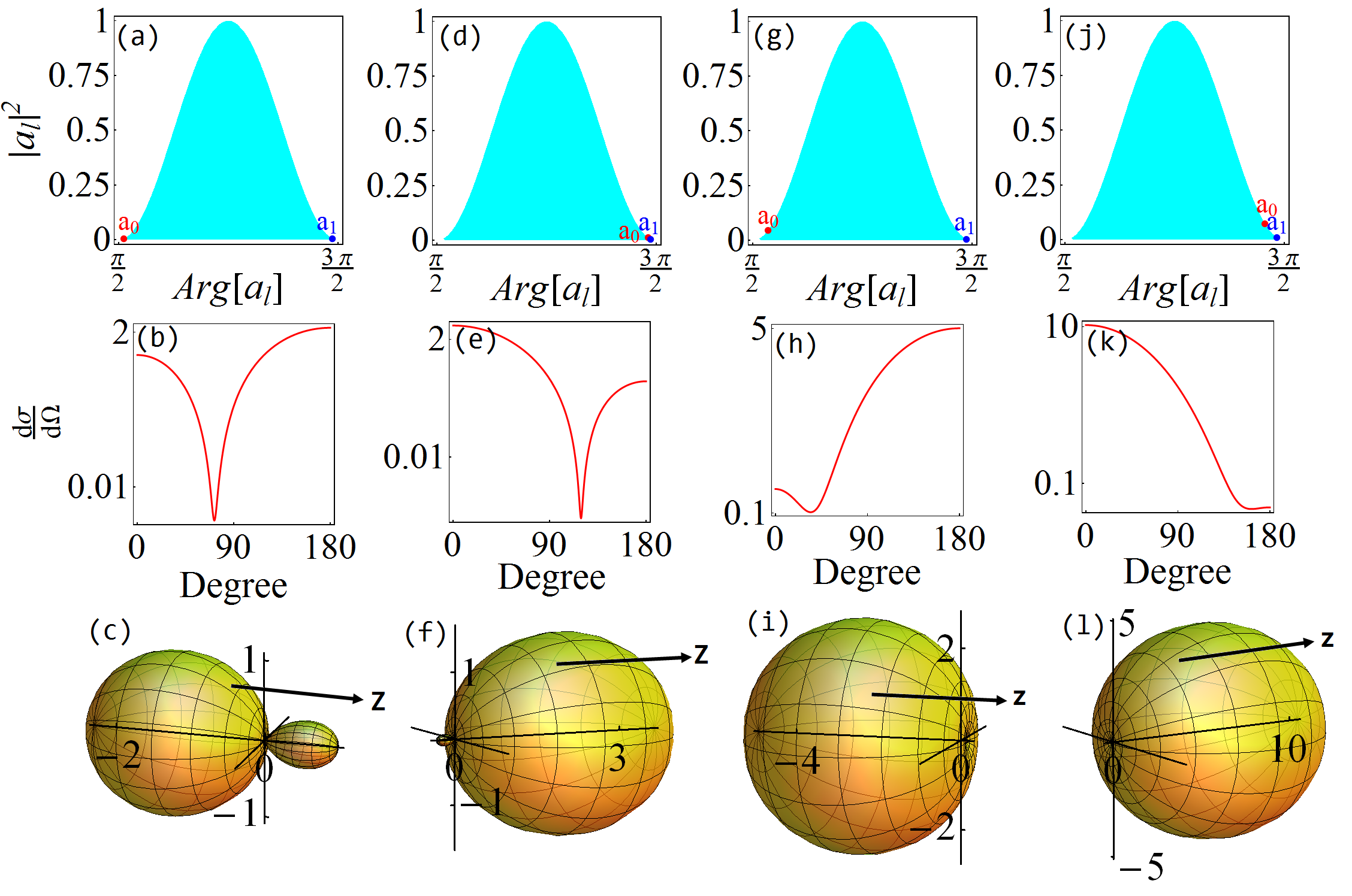
As an example, in the first column of Fig. 3, we demonstrate the scattering pattern with a minimization in the scattering distribution at . The corresponding locations of - and -wave channels in the phase diagram are depicted in Fig. 3(a); while the resulting scattering distributions are represented in log-plot and 3D-plot, i.e., Figs. 3(b) and (c), respectively. Since the phase difference between and is almost , one can expect to have a node in the scattering cross section for . In this example, the system parameters used are all the same as those shown in Fig. 2(f), but with eV and eV.
For , the argument of is . As a result, Eq.(8) can be reduced to the condition . Then, only when , we can have a minimum (or zero) value in the corresponding scattering distribution. Moreover, from the phase diagram shown in Fig. 3(d), we can see that both and locate at the same side, minimizing their phase difference. Due to the same sign in the phases of and , the resulting scattering pattern is enhanced along the forward direction. In Figs 3. (e-f), we report the differential scattering cross section with a dip (node) at . Here, the parameters are all the same as those in Fig. 2 (f), but with and .
It is known that for electromagnetic waves, Kerker et al. proposed to generate zero backward scattering (ZBS) and zero forward scattering (ZFS) through a proper combination of magnetic and electric dipoles kerker . However, due to the optical theorem, there is always a residue in the forward scattering direction for any passive electromagnetic scatterer. Similar to the optical theorem, in the forward direction , the corresponding scattering amplitude , shown in Eq. (6), is also linked to the extinction cross section. Instead of a perfect ZFS, we can only minimize the scatting distribution at the angle . To do this, by fixing , one can perform the minimization for with the conditions and . As shown in the third column in Fig. 3 (g-i), we report the scattering pattern for matter waves with a nearly zero value in the forward scatting by changing the parameters eV and eV. Furthermore, ZBS can be easily generated with a family of scattering events in the phase diagram kerker1 . A typical example for ZBS is illustrated in Fig. 3(j-k) with eV and eV.
Before conclusion, we want to stress that although our discussion is limited to plane wave formalism of quantum scatterers, the partial wave decomposition is independent from the incident wave form. As for other geometry in the quantum scatterer, one may also find a suitable orthogonal basis to decompose the incident and scattered waves. All the physical principles we apply here is to embed the law of passivity on absorption cross section.
IV Conclusion
In conclusion, by considering inelastic scattering for quantum matter waves with the condition , we propose a phase diagram for every angular momentum channel. In a single phase diagram, we can reveal not only the physical bounds on phase and modulus of scattering coefficients, but also indicate the competitions among absorption, extinction and scattering cross sessions. With the help of this phase diagram, we discuss different scenarios through the interference between - and -waves, with the demonstrations to steer the scattering probability distribution from quantum matter waves. We find that with the same phase and modulus from dominant channels, one can have a zero value in the scattering probability distribution at . However, as the strength in the - and -waves are different, we can also minimize the scatting probability distribution at a give angle. With an artificial core-shell quantum dot in semiconductor matrix as an example, such a systematic way by means of the phase diagram is able to provide guidelines in designing quantum scatterers.
Acknowledgments
This work has been supported by Ministry of Science and Technology, Taiwan, under Contract MOST 105-2686-M-007-003-MY4.
References
- (1) A. I. Kuznetsov, A. E. Miroshnichenko, M. L. Brongersma, Yu. S. Kivshar and B. Lukyanchuk, “ Optically resonant dielectric nanostructures,” Science 354, 2472 (2016).
- (2) L. Novotny and N. V. Hulst, “Antennas for light,” Nat. Photon. 5, 83 (2011).
- (3) H. Noh, Y. Chong, A.D. Stone, and H. Cao, “Perfect coupling of light to surface plasmons by coherent absorption,” Phys. Rev. Lett. 108, 186805 (2012).
- (4) Z. Ruan and S. Fan, “Superscattering of Light from Subwavelength Nanostructures,” Phys. Rev. Lett. 105, 013901 (2010).
- (5) A. Alú, and N. Engheta, “Achieving transparency with plasmonic and metamaterial coatings,” Phys. Rev. E 72, 016623 (2005).
- (6) M. Kerker, D.-S. Wang, and C. L. Giles, “Electromagnetic scattering by magnetic spheres,” J. Opt. Soc. Am 73, 765 (1983).
- (7) Y. H. Fu, A. I. Kuznetsov, A. E. Miroshnichenko, Y. F. Yu and B. Lukyanchuk, “Directional visible light scattering by silicon nanoparticles,” Nat. Commun. 4, 1527 (2013).
- (8) S. Person, M. Jain, Z. Lapin, J. J. Saenz, G. Wicks, and . Novotny, “Demonstration of Zero Optical Backscattering from Single Nanoparticles,” Nano Lett. 13, 1806-1809 (2013).
- (9) N. M. Estakhri and A. Alú, “Minimum-scattering superabsorbers,” Phys. Rev. B. 89, 121416(R) (2014).
- (10) J. Y. Lee and R.-K. Lee, “Phase diagram for passive electromagnetic scatterers,” Opt. Express 24, 6480, (2016).
- (11) J. Y. Lee, A. E. Miroshnichenko, R.-K. Lee, “Revisit Kerker’s conditions by means of the phase diagram,” arXiv:1705.03650 (2017).
- (12) N. R. Thomas, N. Kjærgaard, P. S. Julienne, and A. C. Wilson, “Imaging of s and d partial-wave Interference in quantum scattering of identical bosonic atoms,” Phys. Rev. Lett. 93, 173201 (2004).
- (13) N. Kjærgaard, A. S. Mellish, and A. C Wilson, “Differential scattering measurements from a collider for ultracold atoms,” New J. Phys. 6 146 (2004).
- (14) B. L. Liao, M. Zebarjadi, K. Esfarjani, and G. Chen, “Cloaking core-shell nanoparticles from conducting electrons in solids,” Phys. Rev. Lett. 109, 126806 (2012).
- (15) R. Fleury and A. Alú, “Quantum cloaking based on scattering cancellation,” Phys. Rev. B 87, 045423 (2013).
- (16) J. Y. Lee and R.-K. Lee, “Hiding the interior region of core-shell nanoparticles with quantum invisible cloaks,” Phys. Rev. B 89, 155425 (2014).
- (17) M. Zebarjadi, B. Liao, K. Esfarjani, M. Dresselhaus, and G. Chen, “Enhancing the thermoelectric power factor by using invisible dopants,” Adv. Mater. 25, 1577 (2013).
- (18) B. Liao, M. Zebarjadi, K. Esfarjani, and G. Chen, “Isotropic and energy-selective electron cloaks on graphene,” Phys. Rev. B 88, 155432 (2013)
- (19) R. L. Heinisch, F. X. Bronold, and H. Fehske, “Mie scattering analog in graphene: Lensing, particle confinement, and depletion of Klein tunneling,” Phys. Rev. B 87, 155409 (2013).
- (20) D. S. Novikov, “Elastic scattering theory and transport in graphene,” Phys. Rev. B 76, 245435 (2007).
- (21) M. M. Asmar and S. E. Ulloa, “Spin-orbit interaction and isotropic electronic transport in graphene,” Phys. Rev. Lett. 112, 136602 (2014).
- (22) J. Y. Lee, A. E. Miroshnichenko, and R.-K. Lee, “Designing quantum resonant scatterers at subwavelength scale,” Phys. Lett. A 381, 2860 (2017).
- (23) J. J. Sakurai, Modern Quantum Mechanics (Addison-Wesley, 1994).
- (24) F. Schwabl, Quantum mechanics (Springer, 2002).
- (25) R. Fleury and A. Alú, “Furtive quantum sensing using matter-wave cloaks,” Phys. Rev. B 87, 201106(R) (2013).
- (26) Y. D. Chong, L. Ge, H. Cao, and A. D. Stone, “Coherent Perfect Absorbers: Time-Reversed Lasers,” Phys. Rev. Lett. 105, 053901 (2010).
- (27) In the first-order Born approximation, the corresponding scattering amplitude for a general potential is always a real number, but its sign (negative or positive) depends on the barrier or well in potentials book1 , resulting in the phase of scattering coefficients being or .
- (28) L. Valentin, Subatomic Physics: Nuclei and Particles (Hermann, Paris, 1981).
- (29) C. R. Kagan, E. Lifshitz, E. H. Sargent, and D. V. Talapin, “Building devices from colloidal quantum dots,” Science 353, 6302 (2016).
- (30) It should be noted that in this case, by tuning -wave can be excited to be on resonance to the background -wave, forming a Fano-signature in the scattering cross section.