Spatial Heterogeneities and Onset of Passivation Breakdown at Lithium Anode Interfaces
Abstract
Effective passivation of lithium metal surfaces, and prevention of battery-shorting lithium dendrite growth, are critical for implementing lithium-metal-anodes for batteries with increased power densities. Nanoscale surface heterogeneities can be “hot spots” where anode passivation breaks down. Motivated by the observation of lithium dendrites in pores and grain boundaries in all-solid batteries, we examine lithium metal surfaces covered with Li2O and/or LiF thin films with grain boundaries in them. Electronic structure calculations show that, at 0.25 V computed equilibrium overpotential, Li2O grain boundaries with sufficiently large pores can accommodate Li(0) atoms which aid leakage and passivation breakdown. Strain often accompanies Li-insertion; applying a 1.7% strain already lowers the computed overpotential to 0.1 V. Lithium metal nanostructures as thin as 12 Å are thermodynamically favored inside cracks in Li2O films, becoming “incipient lithium filaments.” LiF films are more resistant to lithium metal growth. The models used herein should in turn inform passivating strategies in all-solid-state batteries.
INTRODUCTION
Lithium metal is the most gravimetrically efficient anode candidate material for next-generation batteries.li1 Replacing graphite with Li anode would yield a 3 increase in anode capacity. As Li(s) is extremely electronegative, and reacts with almost all electrolytes in liquid electrolyte-based lithium ion batteries (henceforth LELIB), it requires surface passivation films to block electron tunneling to, and direct chemical contact with the electrolyte.pnnl ; cui ; archer ; jungjohann ; dudney1 The innermost layers of such protective films tend to be inorganic in nature. They are either formed naturally from electrolyte decomposition products (“solid electrolyte interphase” or “SEI”), are artificial coatings, or are formed with solid electrolytes.pearse ; dudney
Even when using protection schemes such as coating lithium metal with passivation films, lithium dendrites may still grow from lithium metal anodes under adverse (e.g., overpotential) conditions. These dendrites can penetrate the separator containing the liquid electrolyte, reach the cathode,naturetem ; garcia and cause a short circuit and possibly a fire. Dendrites are therefore significant battery reliability and safety concerns. Historically, many studies of dendrite formation in liquid electrolyte-based lithium ion batteries (henceforth LELIB) with lithium metal anodes have focused on homogeneous films.newman ; santosh1 ; holzwarth ; yue1 ; yue One popular viewpoint is adopted from electroplating of metal in water, where a solid blocking film is absent, and dendrites are assume to arise from spontaneous, local fluctuations of electric fields. While this viewpoint leads to useful mitigating strategies,pnnl it ignores the fact that lithium nucleation and dissolution occurs at particular locations on the SEI film in LELIB;jungjohann it cannot describe the entire passivation breakdown mechanism. The influence of SEI spatial heterogeneity has been addressed in transition electron microscopy studies.jungjohann ; naturetem However, most lithium dendrites cannot be imaged in battery settings until they are at least 100 nm in diameter, by which time their growth is rapid and unmanageable. Atomic-scale inhomogeneities, from which dendrites may originate, are difficult to image due to the small length scale, low-scattering elemental composition, and the buried nature of the interface. Similarly, modeling of dendrite growth dynamics has focused on the phase-field method, which deals with meso-, not atomic, lengthscales.garcia
Spatial inhomogeneities or “hot spots” on the surfaces of graphite anodes and LiCoO2 cathodes in LELIB are known to exist, leading to battery failure.harris While solid electrolyte-based all-solid lithium ion batteries (henceforth SELIB) are inherently safer than LELIB, lithium metal also reacts with many Li+-conducting solid electrolytes. In particular, dendrites are found to grow inside pores and grain boundaries in some solid electrolyte materials.pore ; pore1 These findings emphasize the importance of studying spatial inhomogeneities at solid-solid interfaces. We hypothesize that atomic lengthscale hot spots at solid-solid interfaces between the SEI and lithium metal anode surfaces are also the locations where passivation starts to break down in LELIB.jungjohann While we focus on the SEI in LELIB, we draw on concepts from SELIB and from electronic materials.shluger ; liair ; fisher ; islam ; twin The models used herein can in turn be applied to interfaces in SELIB studies.
(a) 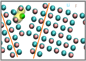
 (b)
(b)
(c) 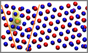
 (d)
(d)
(e) 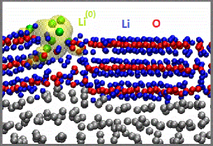
 (f)
(f)
While this work is motivated by the science of dendrite formation, it focuses on lithium metal-induced passivation breakdown on smaller lengthscales that may cause continuous electrolyte decomposition and may be one of the root causes of dendrites under adverse conditions. We apply electronic structure (Density Functional Theory or DFT) calculations to explore electron-blockage breakdown and “incipient lithium filament” formation in the defect regions of the passivation films. Understanding the initial stages of passivation film failure and lithium growth will inform early diagnosis, and will potentially lead to self-healing mechanisms that prevent catastrophic anode failure. DFT can capture bond-breaking events and reveal detrimental through-SEI conduction pathways at sub-nanometer lengthscale; it is complementary to TEM and phase-field studies.naturetem ; garcia We focus on two SEI components, Li2O and LiF. Unlike Li2CO3 and other organic SEI components in LELIB,batt Li2O cannot be readily electrochemically reduced by Li(s). A thin layer of Li2O is predicted to exist on Li surfaces as the innermost inorganic SEI layer,batt unless LiF, likewise stable, has been deposited first. This innermost inorganic layer is arguably the most important SEI component for blocking transport into the liquid electrolyte.yue
Our goal is two-fold: to demonstrate that grain boundaries can aid electron leakage through passivating films, and that cracks initated there can lead to (sub)-nanoscale Li metal (i.e., incipient filament) growth. Regarding leakage, we show that Li(0) atoms can reside and diffuse in Li2O grain boundaries with sufficiently large pore sizes, at V computed overpotential (see definition below) vs. Li+/Li(s) reference. Li(0) has also been proposed to be carriers in Li2CO3 crystals.yueli2co3 This is one possible mechanism responsible for electron transfer through the SEI.tang The specific models examined include grain boundaries in crystalline LiF, Li2O, the heterogeneous boundaries between them (Fig. 1a-d), and thin films containing these grain boundaries deposited on Li metal anode surfaces with well defined electronic voltagessolid (Fig. 1e). Regarding Li metal growth, back-of-the-envelope calculations suggest that Li metal nucleation can already occur inside a 12 Å pre-existing crack within a Li2O film at modest computed overpotentials (see the supporting information document, S.I., Sec. S1). Fig. 1f illustrates a thin Li metal growth inside a nanometer-wide linear crack. Other works have focused on the beneficial effects of heterogeneous interfaces in the SEI.qi16
We stress that grain boundaries in crystals are non-equilibrium structures and reflect kinetic constraints associated with crystal-growth conditions. SEI film formation, which occurs in liquid at room temperature, is already severely kinetically constrained, with many components being thermodynamically metastable.batt The defects in SEI components are even harder to characterize experimentally than undefected SEI regions, and models of such are difficult construct in a systematic way to take proper account of the kinetic formation constraints. Cracks that develop in materials are also clearly kinetically drive.crack Nevertheless, it is critical to study such defects, largely neglected in the literature. In this work, we adopt plausible grain boundary models from crystals in the literatureshluger and use our own construction (Fig. S1 in the S.I.). We show that annealing these models at high temperature, as has been done in some modeling publications,dawson actually yield ambiguous results. High temperature growth are crystal-growth, not SEI-formation, conditions. To some extent, our Li2O grain boundary models can be taken as amorphous regions, which we have postulated to result from electrochemical reduction of other SEI products.batt
METHOD
Construction of the Models
Our static DFT calculations apply periodically replicated simulation cells, the Vienna Atomic Simulation Package (VASP) version 5.3,vasp1 ; vasp1a ; vasp2 ; vasp3 and the Perdew-Burke-Ernzerhof (PBE) functional.pbe All simulation cells considered are overall charge-neutral. A 400 eV planewave energy cutoff is imposed, except that a 500 eV cutoff is used when optimizing simulation cell sizes. Representative simulation cell dimensions, stoichiometries, and Brillouin zone sampling settings are listed in Table 1. Other calculations involve variations on these cells. Many calculations involve slab-like simulation cells with a 10-12 Å vacuum region. In these cases, the dipole moment correction is applied.dipole In calculations of Li monolayer binding energies, spin-polarized DFT is applied if there is an odd number of Li atoms in the simulation cell. Some of these calculations apply the generally more accurate DFT/HSE06 and DFT/PBE0 functionals.hse06a ; hse06b ; hse06c ; pbe0
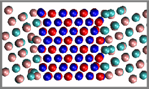
The two main grain boundaries of interest are the (310)/[100] (henceforth called “”) in LiF (001) films, and the one formed by counter-rotating two Li2O (111) slabs by 16.1o (simply referred to as “16o”). They are chosen because of the stability of LiF (001) and Li2O (111) surfaces. Mixed LiF/Li2O boundaries are created by joining the two surfaces of a LiF (310) slab on to Li2O (10) facets (Fig. 1d). In all cases, the -direction is perpendicular to the grain boundaries.
The simulation cell containing two LiF grain boundaries (Fig. 1a) is created as follows. First a LiF crystal at optimal lattice constants is rotated 18.4o and cleaved to expose (310) surfaces in the -direction. A second, mirror-image slab is created by reflecting the first about the - plane. The two are pasted together in the periodically replicated simulation cell to create the two boundaries. The -dimension of the cell is varied while using a higher (500 eV) energy cutoff to obtain the optimal cell length. There are multiple ways to align these simple cubic lattice LiF slabs. The “coincident site lattice” (CSL) approach,fisher which posits that the mirror or junction plane is a (310) plane of atoms common to both slabs, is found to be less energetically favorable than placing the boundary half a lattice constant from both surfaces, with the slabs shifted so that a Li always coordinates to a F (Fig. 1a). This configuration is in fact adopted from Ref. shluger, .
There are limited electronic structure studies of grain boundaries in fluorite lattice structures of AB2 stoichiometry relevant to Li2O.fisher ; islam ; shluger ; brutzel A simple grain boundary is created for Li2O by joining (310) facets. Since the Li2O lattice structure is different from that of LiF, the model used in Fig. 1a is inapplicable, and the CSL approach to is applied instead (Fig. S4 in the S.I.).
For Li2O, the problem with this grain boundary is that one of its orthogonal surfaces is (001). This is the most stable surface for LiF, but is a high energy surface for Li2O. The lowest energy facet of Li2O is (111).li2o is not compatible with a (111) film coating the Li metal surface. Instead, taking the (111) direction as the -axis, we rotate two Li2O slabs in the - plane by 16.1o in opposite directions, join them together in a way to maximize Li-O contacts, and optimize the lattice constant as described in the previous paragraph. This angle is chosen to give a modest system size with best lattice matching with the metal surface supercell. See Fig. 1c and Table 1 for more details. In this “16o” model, manual insertion of two (but not more) 3-atom Li2O formula units into the grain boundary regions is enegetically favorable. As will be discussed, this grain boundary contains sufficient void space, even after insertion of the two Li2O units, to effectively accommodate Li(0). Applying simulated annealing for 12 ps at 500 K and reoptimizing the structure change the total energy of the simulation cell by only 0.2 eV.
| system | dimensions | stoichiometry | -sampling | Figure |
|---|---|---|---|---|
| LiF GB | 28.538.1412.88 | Li160F160 | 212 | Fig. 1a |
| LiF 16o GB | 23.2510.387.05 | Li96F96 | 122 | Fig. 1b |
| Li2O GB | 10.374.6422.92 | Li88O44 | 241 | Fig. S4, S.I. |
| Li2O 16o GB∗∗ | 29.5011.828.06 | Li216O108 | 122 | Fig. 1c |
| LiF/Li2O GB | 27.0313.128.06 | Li180O48F84 | 112 | Fig. 1d |
| LiF GB on Li(s) | 28.5330.0019.32 | Li528F240 | 122 | Fig. 3a-b |
| Li2O GB on Li(s) | 29.5023.6532.00 | Li804O216 | 111 | Fig. 3c-d |
| LiF/Li2O GB on Li(s) | 27.0313.1236.00 | Li506O80F154 | 111 | Fig. 5a-b |
| LiF∗ | 4.074.0724.00 | Li12F12 | 441 | Fig. 2a |
| Li2O∗ | 24.003.288.06 | Li24O12 | 142 | Fig. 2b |
| LiF crack on Li(s) | 27.1520.3636.00 | Li463F140 | 111 | Fig. 7a |
| Li2O crack on Li(s) | 23.6529.2532.00 | Li566O106 | 111 | Fig. 1f |
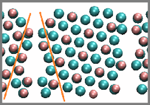
For comparison purposes, a similar 16o grain boundary model for the LiF surface is also created by rotating LiF (111) slabs by 16.1o (Fig. 1b, Table 1).
Finally, mixed LiF/Li2O boundaries are created by joining the two surfaces of a LiF (310) slab on to Li2O (10) facets (Fig. 1d) The good lattice matching of these two surfaces allow cations on one material surface to be coordinated to anions on the other. The cell size is optimized as before. DFT-based molecular dynamics simulations are further conducted at T=500 K for 7 ps, followed by simulated annealing to T=100 K in a 3.5 ps trajectory. This procedure lowers the total energy, but does not lead to passivation of undercoordinated O2- at the grain boundary. Preliminary investigation shows that Li(0) readily bind to these O2-. To improve passivation, four LiF dimer units are inserted into voids between the two components so that all O2- at the interfaces are coordinated to LiF. Geometry optimization is re-initiated. Adding LiF units in this way is found to be energetically favorable after subtracting the relevant LiF chemical potential, and appears more fruitful in passivating the grain boundary region with respect to Li(0) leakage than DFT-based simulated annealing. Since SEI formation occurs at room temperature and is kinetically controlled, it cannot be ruled out that undercoordinated O2- actually exists at these mixed grain boundaries. Our intention is to construct configurations that are least hospitable to Li(0) insertion.
The systems described above are periodically replicated; the simulation cells have no vacuum regions. To determine the effect of Li metal in their vicinity, we cut out Å films of these materials. Li “interlayers” are added to the bottom of the oxide and/or fluoride films, such that a Li atom 2 Å exists below each O2- and/or F- anion (see Sec. S4 below for rationale). These films are then placed on Li (001) or Li (011) surfaces, and the resulting slabs are optimized. Li (001) and Li (011) terminations are used interchangeably because they are of similar surface energies.holzwarth We choose the Li(s) facet that gives the best lattice matching with the inorganic thin film in each case. The lateral lattice constants of the soft Li metal are strained to match to the oxide and/or fluoride. Afterwards, we also apply strain to the entire systems in the direction perpendicular to the grain boundaries by various amounts to mimic curvatures that can develop during lithium plating through the SEI film. If the model contains a Li2O or LiF film on a Li metal surface, the direction is perpendicular to the metal surface. Note that the unstrained Li2O-on-Li(s) system (Table 1) is in fact first strained by 8.4% in three successive steps and recompressed to its original cell dimensions. This procedure is found to lower the energy of the unstrained system by 0.6 eV.
For simulation cells containing interfaces with metallic Li electrode slabs, the true instantaneous electronic voltage () can be computed. At equilibrium, the Li chemical potential should be consistent with the electronic voltage.solid We have not applied simulated annealing to simulation cells with lithium metal anode present. The experimental lithium melting point is 180.5oC, or 453.5 K. Li surfaces melt at even lower temperatures, making simulated annealing impractical.
Properties and Analysis
When attempting to insert Li(0) atoms into grain boundaries, we focus on O2- anions which are coordinated to 6 Li+ or less, manually add a Li near one of these O2-, and optimize the configuration. The reported binding energies represent the lowest energy obtained in several insertion attempts. In perfect crystals of Li2O, each O2- is coordinated to 8 Li+ and each Li+ to 4 O2-. We have not considered inserting a Li+ into any of the grain boundaries, which would create charged simulation cells. While the excess Li+ may enhance Li+ concentration and conductivity, it does not address the failure of passivating film with regard to blocking transport.
The per atom binding energy () of Li(0) inside grain boundaries, or of Li metal films inside cracks, is used to define the computed overpotential . Thus =, where is the number of Li inserted and is the electronic charge. This definition of overpotential broadly corresponds to that of Ref. norskov, . Experimentally, overpotentials arise from kinetic constraints which are not specified in this work. Our definition of merely reflects a convenient way to describe the insertion energy.
Bader charge analysisbader is used to identify localized Li(0) in the insulating Li2O and LiF regions. Like all charge decomposition schemes, such analysis is approximate. It is augmented by examining the spatial distribution of the excess electron . Here we first compute the total charge density of a configuration. Then the total charge density of the same configuration with one or more Bader-identified Li(0) removed is computed, keeping the simulation cell charge-neutral and all other atoms frozen. Finally, the second charge density is subtracted from the first. In the figures, the yellow transparent shapes represent with density values of 0.06 /Å3 or more. We also plot , derived from integrating over the and dimensions.
RESULTS
Bulk-like systems with grain boundaries
First we insert a charge-neutral Li(0) atom into one of the two grain boundaries in simulation cells mimicking bulk-like SEI materials. Fig. 1a depicts an optimized grain boundary in LiF with a Li(0) atom coordinated to two F- anions. The binding energy is eV relative to Li metal cohesive energy (unfavorable). In other words, inserting this Li(0) requires a computed overpotential of 1.41 V relative to the Li+/Li(s) reference. Bader charge analysis indicates that the excess is located on the newly added Li. This is confirmed by plotting the spatial distribution of the excess electron, , in Fig. 1a. We have also added a chain of 4 Li atoms in the grain boundary the periodically replicated cell, which become in effect an infinite 1-D line of Li. In this case, the computed overpotential needed is lower, but remains an unfavorable V. Hence thermally-activated insertion of Li atom into this LiF grain boundary is expected to be rare. The 16o grain boundary for LiF (Fig. 1b) yields a 1.05 V computed overpotential for inserting one Li(0). This LiF film would expose a high energy (111) surface if it were placed on lithium metal surfaces. Hence it is not the focus of our studies.
Li atom insertion into the 16.1o Li2O boundary (Fig. 1c) is more favorable, only requiring an computed overpotential of 0.22 V. Bader charge analysis suggests that the excess is centered not at the added Li, but around another Li+ on the interior grain-boundary surface which is coordinated to 3 O2- ions in the oxide. In Fig. S1 in the S.I., we show that the SEI film is not a metallic conductor. The excess resides inside the band gap. However, the Li(0) can move by multi-atom hopping. The diffusion along the 16o grain boundary is associated with a modest, 0.79 eV barrier. (See the S.I., Sec. S2.) Therefore these excess are reasonably mobile at room temperatures. We also examine a -like grain boundary in a Li2O slab. The computed overpotential for inserting a Li(0) into the void space there is eV, similar to that associated with the boundary in LiF. The difference between the two Li2O grain boundaries appears to have a structural origin. In the optimized configurations after Li(0) insertion, the extra Li(0) in the 16o grain boundary simulation cell is 1.85, 1.86, and 1.90 Å from the 3 nearest O2-, while the distances are 1.88, 1.96, and 2.56 Å in the simulation cell. The nearest distances between the added Li and existing Li+ in the lattice are 2.17 and 2.14 Å in the two cases. These distances favor Li insertion into the 16o grain boundary, which is henceforth our focus.
Surface Energetics
Given the lack of experimental characterization of defect structures in the SEI, a qualitative understanding of the above results is needed to establish they are generally viable, even in disordered regions. It is possible that defect regions in SEI films may be more accuractely described as disordered than as defects in crystalline regions. We propose that one qualitative difference between LiF and Li2O is that LiF is a material with a negative electron affinity,shluger while Li2O supports surface states that can accommodate excess . Electron affinity is relevant because the interior surfaces inside a grain boundary confine a vacuum region. We quantify this effect by comparing an adsorbed monolayer of Li metal on LiF (001) and Li2O (10) (Fig. 2, Table 2). Here the model Li monolayer, as opposed to a well-isolated Li atom on the surface, allows the use of smaller simulation cells, and therefore more costly hybrid DFT functionals which more accurately describe electron localization effects.
The computed overpotentials for adding the Li monolayer are 0.45 V and 0.23 V, respectively. Even Li2O (111), the most stable Li2O facet, exhibits a smaller computed overpotential towards Li monolayer adsorption than LiF (001) (Table 2). Two other Li2O facets actually favor Li monolayer adsorption (Table 2). There are only two (111) surfaces in Li2O crystals, and mulitple facets must be exposed at its grain boundaries.
| facet | (111) | (310) | (10) | “16o” |
|---|---|---|---|---|
| sur. energy | 0.54 | 1.11 | 0.94 | 1.06 |
| Li monolayer | 0.028 | 0.036 |
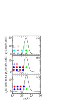
Fig. 2a-b compare the integrated differential charge densities () after adding an Li monolayer to LiF (001) and Li2O (10). On LiF (001), is almost entirely localized on the Li adatoms. On Li2O (10), a more substantial part of has leaked on to the top layer O2- ions. The three-dimensional contour plots in Fig. 2 further confirm this difference. Using the HSE06 and PBE0 functionals yield energy differences that are within 50 meV of those computed using the PBE functional, and profiles that are indistinguishable from PBE predictions.
We have also coated the Li2O surface with a LiF monolayer (Fig. 2c). The computed overpotential associated with adding Li to this surface, 0.64 V, is even less favorable than that on bare LiF (001). LiF can originate from decomposition of PF counter-ions found in organic solvent-based electrolytes, but is more rapidly released when fluoroethylene carbonate (FEC) additive molecules are present.fec1 ; fec2 ; fec3 LiF appears to play a special role in electrode surface passivation.
(a) 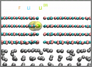
 (b)
(b)
(c) 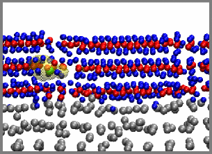
 (d)
(d)
(e) 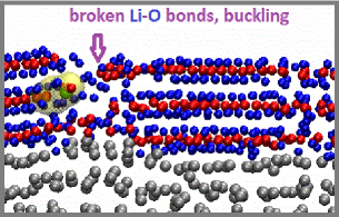
 (f)
(f)
Grain boundaries in films on lithium metal
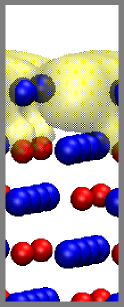
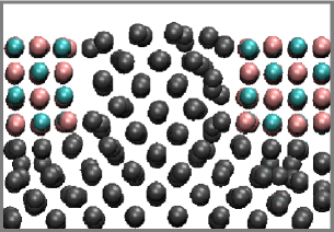
Whether Li(0) can reside inside grain boundaries, however, ultimately depends on the interface-modified Fermi level of the anode in contact with the surface film. Next we attempt to insert Li(0) in thin films with grain boundaries deposited on Li metal. We avoid adding Li near the Li metal surface, where it will simply be absorbed into the metal electrode, or on the outer film surface. Fig. 3a-b show two perspectives of a 10 Å thick LiF film, cut from Fig. 1a deposited on Li metal. A Li(0) is added approximately 6.1 Å from the center of mass of the top Li layer in the anode (Fig. 3a). The computed overpotential is 1.49 V, similar to the LiF model without Li metal (Fig. 1a). Bader analysis indeed reveals that the added Li has an excess .
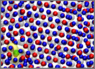
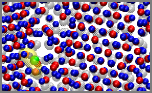
The Li2O film on Li(s) (Fig. 3c-d) already contains two Li(0) atoms in one of its grain boundaries after geometry optimization; manually inserting Li(0) is not needed. One Li(0) is on the outer surface coordinated only to one O2-. Of more interest is the other Li, coordinated to two O2-, halfway through the Li2O film (5.6 Å from the Li metal surface). Removing the latter Li(0) reveals that it has an computed overpotential of only 0.25 V. This overpotential is strongly strain-dependent, and falls to a mere 0.1 V upon applying a 1.7% strain. The existence of a Li(0) inside the Li2O film makes this film non-passivating.
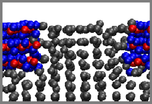
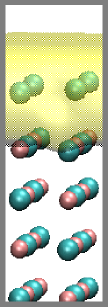
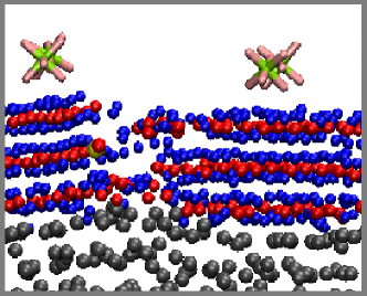
Next, a 3.5 Å, or about 12 %, tensile strain is applied to the Li2O cell with 16o grain boundaries in the -direction, in 3 successive increments each followed by geometry optimization (Fig. 3e-f). This mimics possible surface curvatures arising from Li plating during charging. Silicon anodes are known to expand volumetrically by up to 400% during charging, while graphite can expand its c-axis spacing by 10%. There is less documented data about local strain on SEI-covered Li surfaces. We choose a expansion as the outer limit. Substantial bulging of Li metal anode surface, and buckling of the film above it, are observed upon applying the strain (Fig. 3e). Multiple Li-O ionic bond cleavage events occur at one of the two grain boundaries, leaving a sub-nanometer-sized crack. Inserting 9 Li atoms into the crack is found to require no computed overpotential, yielding a small Li particle on the outside surface of the Li2O film (Fig. 1e). This suggests that incipient lithium metal dendrites can nucleate on sub-nanometer defect features inside cracks in Li2O. Note that we do not claim to separate the effects of strain and broken bonds. As mentioned above, our grain-boundary models can be thought of as amorphous regions in the SEI.
 (c)
(c)
We also address the instantaneous electronic voltage () of the systems we have studied. The work function of the Li metal electrode, modified by the thin film, is the absolute Fermi level of the electrode referenced to vacuum. Dividing the work function by and subtracting 1.37 V yields referenced to Li+/Li(s).solid At equilibrium, should be equal to the Li=(Li++) chemical potential-derived “equilibrium voltage,” or ”computed overpotential,” discussed earlier.
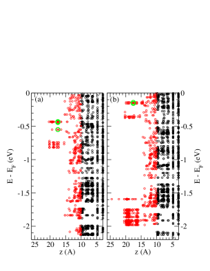
The LiF- and Li2O-coated Li metal surfaces, respectively Fig. 3a-b and Fig. 3c-d, exhibit =0.07 V and 0.16 V. These computed voltages are very close to the Li-plating potential of 0 V vs. Li+/Li(s). Fig. 4a depicts the the energies of Kohn-Sham orbitals along the -direction in the Li2O film strained by 3.5 Å (Fig. 3e-f). Green circles represent orbitals associated with the Li identified by Bader charge analysis to be a Li(0). The relevant, occupied localized orbital on the Li(0) is about 0.4 eV below the lithium metal Fermi level.
In our model, the Li(s)/SEI-film and SEI/vacuum interfaces separate Li(s) from the vacuum region. In more realistic electrochemical systems, the outer surfaces of the inorganic films are in contact with organic SEI components and/or liquid electrolytes. To maintain a 0.0 V applied voltage in those more realistic systems, the charge distribution in the SEI film, electrolyte, and their interfaces may be slightly different. Hence we need to show that varying has only small effects on the existence of Li(0) inside the SEI.
Fig. 4c depicts four PF adsorbed on the outer oxide surface. PF retains all its negative charge in vacuum, without the need for solvation. In the charge-neutral simulation cell, PF induce compensating positive charges on the Li(s) surface. The dipole surface density created exerts a large electric field and raises by 2.66 V.solid But this electric field is found to raise the energy of the Li(0) orbital by only 0.3 eV (Fig. 4b), even though is raised by several times that much. The Li(0) orbital remains occupied (Fig. 4b). The reason is that the is localized away from the thin film-vacuum interface, and does not experience the entire voltage drop through the inorganic film. Note that if the model does not contain an interface, but is a bulk simulation cell (vanishing electric field gradient approximation), DFT would erroneously predict that the voltage has no effect on a charge-neutral defect like Li(0).
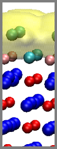
Grain Boundary in Mixed Li2O/LiF Films
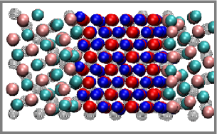
Fig. 5 depicts mixed Li2O/LiF films with grain boundaries on Li metal surfaces. When a 3 Å strain is applied to this sytem (panels (c)-(d)), cleavage of Li-F ionic bonds, rather than cleavage of Li2O from LiF, is observed. Comparing the unstrained and strained configurations, Fig. 5a vs. Fig. 5c and Fig. 5b vs. Fig. 5d, reveals that the Li2O region remains ordered while LiF near the interface exhibits a disordered lattice structure. Note that, by construction, the two LiF/Li2O interfaces in the simulation cell are different and respond to strain differently. The grain boundary atomic environment qualitatively resemble that in LiF, which does not favor Li(0) insertion and has been discussed previously. We have not systematically examined inserting Li(0) here.
(a) 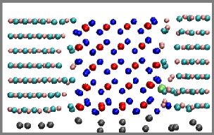
 (b)
(b)
(c) 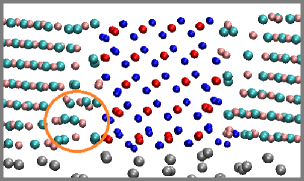
 (d)
(d)
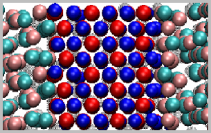
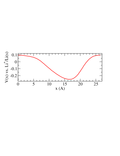
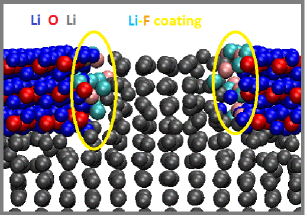
Since Li(s) is metallic, the thin-film-coated anodes studied in this work each exhibits a single work function or at all spatial points inside the metallic region. The unique work function for each model electrode is obtained by averaging over the electrostatic potential in the - plane at a position sufficiently deep into the vacuum region, and using that as the zero energy reference. However, an effective local voltage can be defined by averaging over the -direction. This function is useful for computing tunneling probability at different -positions. Fig. 6a depicts this “local voltage” for the unstrained mixed surface film (Fig. 5a-b) along the -direction perpendicular to the grain boundaries. is found to be inhomogeneous, with variations exceeding 0.25 V and its lowest value at one of the LiF-Li2O grain boundaries.
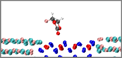
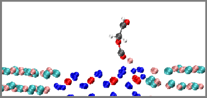
To illustrate the implications of spatial inhomogeneity, we add a fluoroethylene carbonate (FEC) molecule, a popular electrolyte additive,fec1 ; fec2 ; fec3 at two positions. The location at the left-most grain boundary is at a higher voltage. The FEC there has not been electrochemically reduced after a 5 ps DFT-based molecular dynamics trajectory at T=350 K. At the end of the trajectory (Fig. 6b), this FEC has diffused to the almost middle of the Li2O region, but remains intact. The rightmost grain boundary is at a substantially more negative local potential, and is a “hot spot” for passivation breakdown. Placing a FEC there and initiating molecular dynamics leads to FEC reductive decomposition within 0.5 ps (Fig. 6c). Although anecdotal, this evidence underscores the importance of spatial inhomogeneities to electrolyte decomposition – even in the absence of cracks or Li(0) in the grain boundaries.
 (a)
(a)
 (b)
(b)
 (c)
(c)
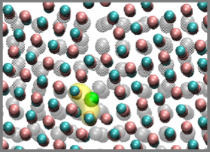
Films with Cracks
Finally, in view of the atomic lengthscale crack developing in strained Li2O films, we also examine surface films with wider gaps or cracks to determine whether Li nanosheets can grow there. Fig. 1f and Fig. 7a depict 10 Å thick Li2O and LiF films, both with 12 Å -wide gaps, on Li(s) surfaces. The computed overpotentials needed for inserting body-center-cubic Li metal into these gaps (126 and 118 Li atoms) are +0.05 and V, respectively. It is therefore energetically favorable to insert a Li(s) nanosheet into the Li2O gap but not LiF. Fig. 7b depicts the Li2O film with a gap decorated with LiF dimers at a surface density of 2.9 nm-2. The configuration is optimized before introducing 118 Li inside the gap in the cell. The computed overpotential needed to insert that Li metal sheet is V, suggesting that Li insertion may be thermodynamically favorable at 0 V vs. Li+/Li(s). While LiF dimer-coated Li2O yields an unfavorable monolayer Li adsorption energy (Fig. 2c), the F- anions at the surface can be readily absorbed into the added Li metal nanosheet, negating that lithium-phobic condition. A thicker layer of LiF is apparently needed to impede Li intrusion. These predictions may have impact on future attempts at passivating boundaries or cracks in SEI.
 (a)
(a)
 (b)
(b)
CONCLUSIONS
In conclusion, this computational work illustrates the effects of atomic lengthscale inhomogeneities in passivation films covering lithium anode surfaces. The lengthscale considered is too small to be conclusively imaged using current experimental methods, but our predictions will help motivate future experimental work. Both LiF and Li2O on Li metal surfaces exhibit wide band gaps and block electrons if they are defect free.yue But mobile Li(0) is found to reside in and diffuse along Li2O grain boundaries at V computed overpotential if there is sufficient void space there. Strain often accompanies Li+ insertion into anodes. Applying a 1.7% strain lowers the computed overpotential needed for Li(0) formation in the grain boundary to 0.1 V. Furthermore, there can be significant spatial fluctuations in the local potential. As such, Li(0) species may be responsible for through-SEI transport, initial passivation breakdown of surface films, and slow increase of impedance at the interface as the battery ages. Upon further application of strain, subnanometer-sized particles of Li metal can grow in atomic lengthscale gaps that develop at Li2O grain boundaries, forming “incipient lithium filaments” that may cause subsequent growth of dendrites under adverse conditions. These findings appear qualitatively consistent with the fact that applying pressure, which reduces void spaces, improves the performance of Li metal anodes.pressure The negative electron affinity material LiF is much more resistant to Li(0) insertion. Our grain boundary models are meant to represent defected/amorphous regions of SEI inorganic layers, the growth of which are kinetically controlled. Therefore we also illustrate the fundamental material and surface difference between Li2O and LiF by considering the energetics of monolayer Li metal films on these surfaces. The results suggest that the difference between these materials in the SEI is likely to exist independent of the specific model used. This simple test can potentially be used to examine the -blocking ability of novel, artificial coating layers and their defects. In general, we postulate that additives and new strategies need to mitigate passivation failures of Li anode protection films at inhomogeneities, not just for defect-free films.
ACKNOWLEGEMENTS
This work was performed, in part, at the Center for Integrated Nanotechnologies, an Office of Science User Facility operated for the U.S. Department of Energy (DOE) Office of Science. Sandia National Laboratories is a multi-mission laboratory managed and operated by National Technology and Engineering Solutions of Sandia, LLC., a wholly owned subsidiary of Honeywell International, Inc., for the U.S. Department of Energy’s National Nuclear Security Administration under contract DE-NA-0003525. KL, who performed the calculations, was supported by the Assistant Secretary for Energy Efficiency and Renewable Energy, Office of Vehicle Technologies of the U.S. Department of Energy under Contract No. DE-AC02-05CH11231, Subcontract No. 7060634 under the Advanced Batteries Materials Research (BMR) Program. KLJ, who provided the experimental motivation, was supported by Nanostructures for Electrical Energy Storage (NEES), an Energy Frontier Research Center funded by the U.S. Department of Energy, Office of Science, Office of Basic Energy Sciences under Award Number DESC0001160.
Supporting Information for Publication
Supporting information is available free of charge on the ACS Publications website at DOI:
Details of models used; Li(0) diffusion along grain boundaries; Li adsorption on planar surfaces; interfaces between crystalline LiF/Li2O and Li metal; Li2O grain boundaries; model with a thicker Li2O surface film.
References
- (1) Xu, W.; Wang, J.; Ding, F.; Chen, X.; Nasybulin, E.; Zhang, Y.; Zhang, J.-G. Lithium Metal Anodes for Rechargeable Batteries. Energy Envir. Sci. 2014, 7, 513-537.
- (2) Ding, F.; Xu, W.; Graff, G.L.; Zhang, J.; Sushko, M.L.; Chen, X.; Shao, Y.; Engelhard, M.H.; Nie, Z.; Xiao, J.; Liu, X.; Sushko, P.V.; Liu, J., Zhang, J.-G. Dendrite-free Lithium Deposition via Self-Healing Electrostatic Shield Mechanism. J. Am. Chem. Soc. 2013, 135, 4450-4456.
- (3) Liu, W.; Lin, D.; Pei, A.; Cui, Y. Stabilizing Lithium Metal Anodes by Uniform Li-Ion Flux Distribution in Nanochannel Confinement. J. Am. Chem. Soc. 2016, 138, 15443-15450.
- (4) Choudhury, S.; Mangal, R.; Agrawal, A.; Archer, L.A. A Highly Reversible Room-Temperature Lithium Metal Battery Based on Crosslinked Hairy Nanoparticles. Nat. Commun. 2016, 6, 10101.
- (5) Leenheer, A.J.; Jungjohann, K.L.; Zavadil, K.R.; Sullivan, J.P.; Harris, C.T. Lithium Electrodeposition Dynamics in Aprotic Electrolyte Observed in Situ via Transmission Electron Microscopy. ACS Nano 2015, 9, 4379-4389.
- (6) Sacci, R.L.; Black, J.M.; Balke, N.; Dudney, N.J.; Moore, K.L.; Unocic, R.R. Nanoscale Imaging of Fundamental Li Battery Chemistry: Solid-Electrolyte Interphase Formation and Preferential Growth of Lithium Metal Nanoclusters. Nano Lett. 2015, 15, 2011-2018.
- (7) Kozen, A.C.; Lin, C.F.; Pearse, A.J.; Schroeder, M.A.; Han, X.G.; Hu, L.B.; Lee, S.B.; Rubloff, G.W.; Noked, M. Next-generation Lithium Metal Anode Engineering via Atomic Layer Deposition. ACS Nano 2015, 9, 5884-5892.
- (8) Ma, C.; Cheng, Y.; Yin, K.; Luo, J.; Sharafi, A.; Sakamoto, J.; Li, J.; More, K.L.; Dudney, N.J.; Chi, M. Interfacial Stability of Li Metal-Solid Electrolyte Elucidated via in Situ Electron Microscopy. Nano Lett. 2016, 16, 7030-7036.
- (9) Harry, K.J.; Hallinan, D.T.; Parkinson, D.Y.; MacDowell, A.A.; Balsara, N.P. Detection of Subsurface Structures Underneath Dendrites Formed on Cycled Lithium Metal Electrodes. Nature Materials 2014, 13, 69-73.
- (10) Jana, A.; Ely, D.R.; Garcia, R.E. Dendrite-separator Interactions in Lithium-based Batteries. J. Power Sources 2015, 275, 912-921.
- (11) Ferrese, A.; Newman, J. Mechanical Deformation of a Lithium-Metal Anode due to a Very Stiff Separator, J. Electrochem. Soc. 2014, 161, A1350-A1359, and references therein.
- (12) Santosh, K.C.; Xiong, K.; Longo, R.C.; Cho, K. Interface Phenomena Between Li Anode and Lithium Phosphate Electrolyte for Li-Ion Battery. J. Power Sources 2014, 244, 136-142.
- (13) Lepley, N.D.; Holzwarth, N.A.W. Modeling Interfaces Between Solids: Application to Li Battery Materials. Phys. Rev. B 2015, 92, 214201.
- (14) Liu, Z.; Qi, Y.; Lin, Y.X.; Chen, L.; Lu, P.; Chen, L.Q. Interfacial Study on Solid Electrolyte Interphase at Li Metal Anode: Implication for Li Dendrite Growth. J. Electrochem. Soc. 2016, 163, A592-A598.
- (15) Lin, Y.-X.; Liu, Z.; Leung, K.; Chen, L.Q.; Lu, P.; Qi, Y. Connecting the Irreversible Capacity Loss in Li-ion Batteries with the Electronic Insulating Properties of Solid Electrolyte Interphase (SEI) Components. J. Power Sources 2016, 309, 221-230.
- (16) Harris, S.J.; Lu, P. Effects of Inhomogeneities – Nanoscale to Mesoscale – on the Durability of Li-Ion Batteries. J. Phys. Chem. C 2013, 117, 6481-6492.
- (17) Ren, Y.; Shen, Y.; Lin, Y., Nan, C.-W. Direct Observation of Lithium Dendrites inside Garnet-type Lithium-ion Solid Electrolyte. Electrochem. Commun. 2015, 57, 27-30.
- (18) Cheng, E.J.; Sharafi, A.; Sakamoto, J. Intergranular Li Metal Propagation Through Polycrystalline Li6.25Al0.25La3Zr2O12 Ceramic Electrolyte. Electrochim. Acta 2017, 223, 85-91.
- (19) McKenna, K.P.; Shluger, A.L. Electron-trapping Polycrystalline Materials with Negative Electron Affinity. Nature Materials 2008, 7, 859-862.
- (20) Geng, W.T.; He, B.L.; Ohno, T. Grain Boundary Induced Conductivity in Li2O2. J. Phys. Chem. C 2013, 117, 25222-25228.
- (21) Fisher, C.A.J.; Matsubara, H. Molecular Dynamics Investigations of Grain Boundary Phenomena in Cubic Zirconia. Comput. Mater. Sci. 1999, 14, 177-184.
- (22) Olson, C.L.; Nelson, J.; Islam, M.S. Defect Chemistry, Surface Structures, and Lithium Insertion in Anatase TiO2. J. Phys. Chem. 2006, 110, 9995-10001.
- (23) Nie, A.; Gan, L.-Y.; Cheng, Y.; Li, Q.; Yuan, Y.; Mashayek, F.; Wang, H.; Klie, R.; Schwingenschlogl, U.; Shahbasizn-Yassar, R. Twin Boundary-Assisted Lithium Ion Transport. Nano Lett. 2015, 15, 610-615.
- (24) Leung, K.; Soto, F.; Hankins, K.; Balbuena, P.B.; Harrison, K.L. Stability of Solid Electrolyte Interphase Components on Lithium Metal and Reactive Anode Material Surfaces. J. Phys. Chem. C 2016, 120, 6302-6313.
- (25) Shi, Q.; Lu, P.; Liu, Z.; Qi, Y.; Hector Jr., L.G.; Li, H.; Harris, S.J. Direct Calculation of Li-ion Transport in the Solid Electrolyte Interphase. J. Am. Chem. Soc. 2012, 134, 15476-15487.
- (26) Tang, M.; Newman, J. Why is the Solid-Electrolyte-Interphase Selective? Through-Film Ferrocenium Reduction on Highly Oriented Pyrolytic Graphite. J. Electrochem. Soc. 2012, 159, A1922-A1927.
- (27) Zhang, Q.; Pan, J.; Lu, P.; Liu, Z.; Verbrugge, M.W.; Sheldon, B.W.; Cheng, Y.-T.; Qi, Y.; Xiao, X. Synergetic Effects of Inorganic Components in Solid Electrolyte Interphase on High Cycle Efficiency of Lithium Ion Batteries. Nano Lett. 2016, 16, 2011-2016.
- (28) Leung, K.; Leenheer, A. How Voltage Drops are Manifested by Lithium Ion Configurations at Interfaces and in Thin Films on Battery Electrodes. J. Phys. Chem. C 2015, 119, 10234-10246.
- (29) Holland, D.; Marder, M. Ideal Brittle Fracture of Silicon Studied with Molecular Dynamics. Phys. Rev. Lett. 1998, 80, 746-749.
- (30) Dawson, J.A.; Chen, H.; Tanaka, I. First-Principles Calculations of Oxygen Vacancy Formation and Metallic Behavior at a -MnO2 Grain Boundary. ACS Appl. Mater. Interface 2015, 7, 1726-1734.
- (31) Kresse, G.; Furthmüller, J. Efficient Iterative Schemes for Ab Initio Total-Energy Calculations Using a Plane-wave Basis Set. Phys. Rev. B 1996, 54, 11169-11186.
- (32) Kresse, G.; Furthmüller, J. Efficiency of Ab-initio Total Energy Calculations for Metals and Semiconductors using a Plane-Wave Basis Set. Comput. Mater. Sci. 1996, 6, 15-50.
- (33) Kresse G.; Joubert, D. From Ultrasoft Pseudopotentials to the Projector Augmented-Wave Method. Phys. Rev. B 1999, 59, 1758-1775.
- (34) Paier, J.; Marsman, M.; Kresse, G. Why Does the B3LYP Hybrid Functional Fail for Metals? J. Chem. Phys. 2007, 127, 024103.
- (35) Perdew, J.P., Burke, K.; Ernzerhof, .M. Generalized Gradient Approximation Made Simple. Phys. Rev. Lett. 1996, 77, 3865-3868.
- (36) Neugebauer, J.; Scheffler, M. Adsorbate-Substrate and Adsorbate-Adsorbate Interactions of Na and K adlayers on Al(111). Phys. Rev. B 1992, 46, 16067-16080.
- (37) Heyd, J.; Scuseria, G.E.; Ernzerhof, M. Hybrid Functionals based on a Screened Coulomb Potential. J. Chem. Phys. 2003, 118, 8207-8215.
- (38) Heyd, J.; Scuseria, G.E.; Ernzerhof, M. Hybrid Functionals Based on a Screened Coulomb Potential. J. Chem. Phys. 2006, 124, 219906.
- (39) Vydrov, O.A.; Heyd, J.; Krukau, A.V.; Scuseria, G.E. Importance of Short-Range versus Long-Range Hartree Fock Exchange for the Performance of Hybrid Density Functionals. J. Chem. Phys., 2006, 125, 074106.
- (40) Adamo, C.; Barone, V. Towards Reliable Density Functional Methods without Adjustable Parameters: the PBE0 Model. J. Chem. Phys. 1999, 110, 6158-6170.
- (41) Van Brutzel, L.; Vincent-Aublant E. Grain Boundary Influence on Displacement Cascades in UO2: A Molecular Dynamics Study. J. Nuc. Mater. 2008, 377, 522-527.
- (42) Hayoun, M.; Meyer, M. Surface Effects on Atomic Diffusion in a Superionic Conductor: A Molecular dynamics Study of Lithium Oxide. Sur. Sci. 2013, 607, 118-123.
- (43) Hummelshoj, J.S.; Luntz, A.C.; Norskov, J.K. Theoretical Evidence for Low Kinetic Overpotential in Li-O2 Electrochemistry. J. Chem. Phys. 2013, 138, 034703.
- (44) Henkelman, G.; Arnaldsson, A.; Jónsson, H. A Fast and Robust Algorithm for Bader Decomposition of Charge Density. Comput. Mater. Sci. 2006, 36, 354-360.
- (45) Leung, K.; Rempe, S.B.; Foster, M.E.; Ma, Y.; Martinez de la Hoz, J.M.; Sai, N.; Balbuena, P.B. Modeling Electrochemical Decomposition of Fluoroethylene Carbonate on Silicon Anode Surfaces in Lithium Ion Batteries J. Electrochem. Soc., 2014, 161, A213-A221, and references therein.
- (46) Okuno, Y.; Ushirogata, K.; Sodeyama, K.; Tateyama, Y. Decomposition of the Fluoroethylene Carbonate Additive and the Glue Effect of Lithium Fluoride Products for the Solid Electrolyte Interphase: an Ab Initio Study. Phys. Chem. Chem. Phys. 2016, 18, 8643-8653.
- (47) Jung, R.; Metzger, M.; Haering, D.; Solchenbach S.; Marino, C.; Tsiouvaras, N.; Stinner, C.; Gasteiger, H.A. Consumption of Fluoroethylene Carbonate (FEC) on Si-C Composite Electrodes for Li-Ion Batteries. J. Electrochem. Soc. 2016, 163, A1705-A1716.
- (48) Mikhaylik, Y.; Kovalev, I.; Schock, R.; Kumaresan, K.; Xu, J.; Affinito, J. High Energy Rechargeabe Li-S Cells for EV Application. Status, Remaining Problems and Solutions. ECS Trans. 2010, 25, 23-34.