Phase-tunable Josephson thermal router
Since the the first studies of thermodynamics, heat transport has been a crucial element for the understanding of any thermal system. Quantum mechanics has introduced new appealing ingredients for the manipulation of heat currents, such as the long-range coherence of the superconducting condensate MakiGriffin ; FornieriRev . The latter has been exploited by phase-coherent caloritronics, a young field of nanoscience, to realize Josephson heat interferometers GiazottoNature ; MartinezNature ; FornieriNature ; FornieriNature2 , which can control electronic thermal currents as a function of the external magnetic flux. So far, only one output temperature has been modulated, while multi-terminal devices that allow to distribute the heat flux among different reservoirs are still missing. Here, we report the experimental realization of a phase-tunable thermal router able to control the heat transferred between two terminals residing at different temperatures. Thanks to the Josephson effect, our structure allows to regulate the thermal gradient between the output electrodes until reaching its inversion. Together with interferometers GiazottoNature ; MartinezNature , heat diodes MartinezNatRect ; MartinezAPL and thermal memories Guarcello2 ; FornieriPRB , the thermal router represents a fundamental step towards the thermal conversion of non-linear electronic devices FornieriRev , and the realization of caloritronic logic components PaolucciLogic ; LiRev .
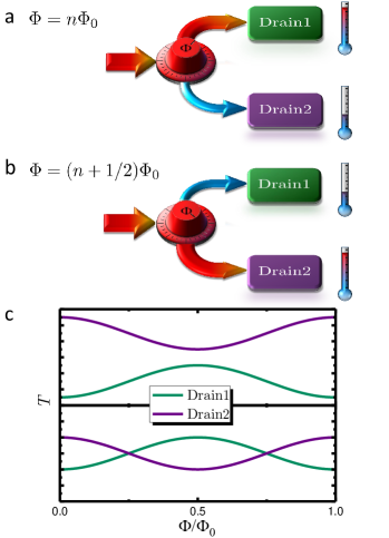
A thermal router is a device that allows to direct an incoming heat flow to a (drain) terminal of choice Bosisio1 (see Fig. 1a, b). As shown in Fig. 1c, we can define two working regimes: in the splitting regime, one of the drain temperatures is always higher than the other, while in the swapping regime the output thermal gradient is inverted as a function of an external modulating parameter, i.e., the knob represented in Fig. 1a and 1b. This knob can be efficiently embodied by a magnetic flux threading a temperature-biased direct-current superconducting quantum interference device (dc SQUID) GiazottoNature . The latter consists of a loop composed by two superconductors S1 and S2 residing at electronic temperatures and , respectively, and connected by two Josephson tunnel junctions (JJs) in parallel, labelled ‘A’ and ‘B’. If we impose a temperature gradient across the SQUID by raising above , a steady state electronic heat current flows through the interferometer GiazottoAPL :
| (1) |
where and are the incoherent quasi particle contribution and the phase-coherent component of the heat current flowing through junction ‘A’, respectively. The second term originates from energy-carrying tunneling processes involving creation and destruction of Cooper pairs on both sides of the JJs Guttman ; Barone (see Methods). Consequently, it depends on the phase difference between the superconducting condensates across the JJs and can therefore be modulated by the magnetic flux piercing the SQUID loop Tinkham . Finally, in Eq. (1) the parameter accounts for the asymmetry of the normal-state resistances and of the interferometer JJs, whereas Wb is the superconducting flux quantum.
Here, we experimentally demonstrate that a temperature-biased dc SQUID can work as the directional core of a Josephson thermal router able to control the thermal gradients between two drain electrodes in a superconducting hybrid circuit. The router operation is regulated by two main control parameters: the magnetic flux threading the SQUID and the temperature of the lattice phonons. In our case, the latter are fully thermalized with the substrate phonons residing at the bath temperature, , thanks to the vanishing Kapitza resistance between thin metallic films and the substrate at low temperatures GiazottoRev ; Wellstood ; GiazottoNature ; MartinezNature ; MartinezNatRect ; FornieriNature ; FornieriNature2 . As we explained previously, can modulate according to Eq. (1), while instead the average value of the oscillating drain temperatures is mainly controlled by . As we shall argue, by increasing the value of , we can tune the working regime of the thermal router, which can operate as a splitter or as a swapper.
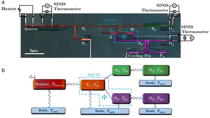
The realization of the thermal router is shown in Fig. 2a and 2b. The structure was fabricated by electron-beam lithography and three-angle shadow-mask evaporation of metals with in situ oxidation (see Methods). Aluminium (with a critical temperature ) was used for all the superconducting parts, and Al0.98Mn0.02 was used for the normal metal (N) electrodes MartinezNature ; MartinezNatRect ; TaskinenAPL ; FornieriNature . The device consists of a N source electrode tunnel-coupled to the superconducting island S1, forming the upper branch of the SQUID. As mentioned in the introduction, the electrode S1 is connected to the lower branch of the SQUID S2 by means of the JJs ‘A’ and ‘B’. Moreover, S1 is tunnel-coupled to the superconducting island S3, which is necessary to reach the swapping regime, as we shall explain later. S3 and S2, in turn, are tunnel-coupled to the N drains D1 and D2, respectively (see Fig. 2a). A N electrode acting as a cooling fin was tunnel coupled to S2 (with a normal state resistance ) in order to maintain a suitable thermal gradient across the SQUID GiazottoRev ; MartinezNatRect . For the electrical characterization, two superconducting probes P1 and P2 Tinkham ; GiazottoAPL were tunnel-coupled to S1 and S2, respectively, with normal state resistances and . The JJ between S1 and S3 () was designed to obtain thermal decoupling of D1 from S1. The normal state resistances of the source and drains junctions are k, k and k, respectively.
Finally, source and drain electrodes are tunnel-coupled to superconducting probes (see Fig. 2a) realizing NIS junctions (normal state resistance of ) used as thermometers and Joule heaters GiazottoRev .
To extract the SQUID parameters, we measured the magnetic interference pattern of its Josephson critical current via a conventional four-wire technique, through P1 and P2 probes. From the fit of the data we obtained junction ‘A’ normal-state resistance and the asymmetry parameter GiazottoNature ; Barone ; SQUIDhandbook .
On the other hand, thermal measurements were performed using the set-up sketched in Fig. 2a. By injecting a Joule power into the source, we can raise its electronic temperature above . In this way, we can increase the electronic temperature of S1 and generate a thermal gradient across the SQUID at the core of the thermal router. This assumption is expected to hold thanks to the cooling fin connected to S2. Indeed, the cooling fin extends into a large volume which provides a good thermalization with and represents an efficient channel to reduce below .
Therefore, a finite heat current flows through the SQUID and can be modulated by the magnetic flux piercing its loop. In particular, if we set and to fixed values, is minimized when (being an integer) [see Eq. (1)] leading to a maximum of . For , instead, is maximized and has a local minimum. As a consequence, the heat current flowing out of S1 towards S3 is maximized for , while the heat current flowing out of S2 results to be minimized. The opposite situation is obtained when . Even though heat currents are not directly detectable, the described behaviour is reflected by the temperatures and of the drain electrodes connected to the different branches of the SQUID, which are expected to oscillate periodically with opposite phase dependence. Moreover, the superconducting island S3 is introduced between S1 and D1 in order to reduce the difference between and and reach the swapping regime.
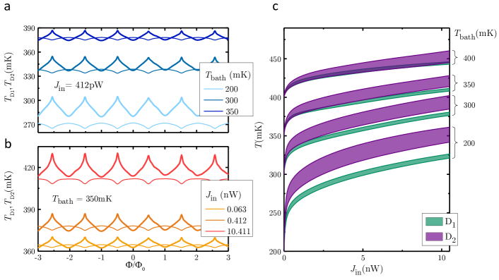
The thermal behaviour of the D1 and D2 as a function of the magnetic flux is shown in Fig. 3a and 3b for different values of and , respectively. As anticipated, the drain temperatures manifestly demonstrate an opposite dependence on the magnetic flux: the minima and maxima of the curves corresponding to different drains are inverted. At low bath temperature, the oscillations do not overlap, so the thermal router is operating in the splitting regime. As we increase the value of , the average temperatures of the drain electrodes and tend to approach each other, leading to overlapping modulations for mK. This behaviour is summarized by Fig. 3c, which displays the total swing amplitudes of and as a function of for different bath temperatures. The injected power also plays an important role, since it can raise more efficiently than . This is due to the stronger coupling of S2 to S1 as compared to that between S1 and S3. In the splitting regime, we obtain a maximum separation between and of 40 mK for nW at mK, while in the swapping regime a maximum temperature inversion of 4 mK is obtained for nW at mK. To account for our observations we have elaborated a thermal model describing our structure (sketched in Fig. 2b). In this model, we take into account the predominant mechanisms of energy exchange, i.e, the electronic heat currents flowing through SIS, SIN or NIS junctions and the electron-phonon coupling in the normal metal electrodes (see Methods). For any given , and , the steady-state electronic temperatures of every part of the device can be determined by solving the following system of energy-balance equations:
| (2a) | |||||
| (2b) | |||||
| (2c) | |||||
| (2d) | |||||
| (2e) | |||||
| (2f) |
These equations account for the detailed thermal budget of each electrode of the structure by equating the sum of all incoming and outgoing heat currents. In particular, Eq. (2a) refers to the thermal budget in the source, Eq. (2b) to S1, Eq. (2c) to S2, Eq. (2d) to S3, and finally Eqs. (2e) and Eq. (2f) describe the energy exchange of D1 and D2, respectively. In the energy-balance equations, represent the heat currents released from S1 and S2 to the superconducting probes P1 and P2, is the heat flux between S1 and S3, whereas accounts for the power delivered by S2 to the cooling fin. Moreover, are the heat currents flowing into D1,2, , where N=Source,D1,D2, are the heat losses due to the electron-phonon coupling in the electrodes and, finally, consider the energy released by D1 and D2 to the superconducting thermometers. Each term of the energy-balance equations is detailed in the Methods. In the model, we neglect photon-mediated thermal transport owing to poor impedance matching between the source and drains electrodes meschke ; Bosisio ; Timofeev2 ; Pascal , as well as electron-phonon coupling in all the superconducting parts of the structure due to their reduced volume and low Timofeev1 .
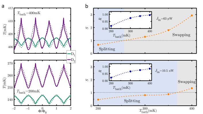
The model provides a good agreement with the data for both drains at different bath temperature and different injected power, as shown in Fig.4a for . Three parameters were extracted from the fit. The first is the resistance of the probe P2 (), which is not directly obtainable from the electrical measurements (see Methods). The other two parameters are the parasitic heat currents injected by the thermometers of the drains, which remain on the order of the femtowatt (in particular J1 varies from 1 fW to 8 fW and J fW). The origin of these parasitic powers may be thermal noise and fluctuations in the thermometers meschke .
In order to characterize the performance of our thermal router, we define two parameters outlining its working regime: the ratio between the average drain temperatures , and the ratio between the sum of the amplitudes of the average drain temperature swings and the difference between the drain average temperatures . As shown in the insets of Fig. 4b, displays the gradual approach of the drain average temperatures as is increased, which is not influenced by the injected power . On the other hand, takes into account the overlap of the thermal oscillations of the two drains. By definition is lower than 1 if the router works in the splitting regime, while it is greater than 1 if the router is in the swapping regime. The behaviour of as function of for two different values of is shown in Fig. 4b. The injected power strongly affects , influencing the transition point between the different working regimes of the thermal router. This is also clear from Fig.3c: at higher injected power the router reaches the swapping regime at larger values in .
In summary, we have realized a phase-tunable Josephson thermal router able to control with very high accuracy the heat transferred among two terminals residing at different temperatures. The router provides high versatility of use, allowing to work in different regimes, easily accessible by varying the bath temperature. In the splitting regime, we obtain a maximum separation of the average drain temperatures of 40 mK, whereas in the swapping regime, our device can invert the thermal gradient between two reservoirs, with a maximum inversion of 4 mK. The latter capability may be also useful for mesoscopic thermal machines Kosolof ; Benenti . The device is a proof of concept which can be easily improved by using a double loop SQUID FornieriNature to achieve a finer control, or a thermal JJ FornieriNature2 to increase the amount of heat that can be controlled at the core of the structure. We wish to stress that our thermal router is a modular element, and it can be easily extended to multiple output terminals. Indeed the output of a thermal router can be used as the input for the next one, thus multiplying the output terminals. Finally, one of the fundamental requests of thermal logic PaolucciLogic , namely switching thermal signals among different channels, is answered by the phase-tunable thermal router.
References
References
- (1) Maki, K. & Griffin, A. Entropy transport between two superconductors by electron tunneling. Phys. Rev. Lett. 15, 921-923 (1965).
- (2) Fornieri, A. & Giazotto, F. Towards phase-coherent caloritronics in superconducting circuits Nat. Nanotechnol 12 944-952 (2017).
- (3) Giazotto, F. & Martínez-Pérez, M. J. The Josephson heat interferometer. Nature 492, 401-405 (2012).
- (4) Martínez-Pérez, M. J. & Giazotto, F. A quantum diffractor for thermal flux. Nat. Commun. 5, 3579 (2014).
- (5) Fornieri, A., Blanc, C., Bosisio, R., D’Ambrosio, S. & Giazotto, F. Nanoscale phase engineering of thermal transport with a Josephson heat modulator. Nat. Nanotechnol. 11, 258-262 (2016).
- (6) Fornieri, A., Timossi, G., Virtanen, P., Solinas, P. & Giazotto, F. 0- phase-controllable thermal Josephson junction. Nat. Nanotechnol. 12, 425-429 (2017).
- (7) Martínez-Pérez, M. J., Fornieri, A. & Giazotto, F. Rectification of electronic heat current by a hybrid thermal diode. Nat. Nanotechnol. 10, 303-307 (2015).
- (8) Martínez-Pérez, M. J. & Giazotto, F. Efficient phase-tunable Josephson thermal rectifier. Appl. Phys. Lett. 102, 182602 (2013).
- (9) Guarcello, C., Solinas, P., Braggio, A., Di Ventra, M. & Giazotto, F. A Josephson thermal memory arXiv:1706.05323 [cond-mat.mes-hall] (2017).
- (10) Fornieri, A., Timossi, G., Bosisio, R., Solinas, P. & Giazotto, F. Negative differential thermal conductance and heat amplification in superconducting hybrid devices. Phys. Rev. B 93, 134508 (2016).
- (11) Paolucci, F., Marchegiani, G., Strambini, E. & Giazotto, F. Phase-tunable thermal logic: computation with heat. arXiv:1709.08609 (2017).
- (12) Li, N. et al. Phononics: manipulating heat flow with electronic analogs and beyond. Rev. Mod. Phys. 84, 1045-1066 (2012).
- (13) Bosisio, R. et al. A magnetic thermal switch for heat management at the nanoscale. Phys. Rev. B 91, 205420 (2015)
- (14) Giazotto, F. & Martínez-Pérez, M. J. Phase-controlled superconducting heat-flux quantum modulator. Appl. Phys. Lett. 101, 102601 (2012).
- (15) Guttman, G. D., Nathanson, B., Ben-Jacob, E. & Bergman, D. J. Phase-dependent thermal transport in Josephson junctions. Phys. Rev. B 55, 3849-3855 (1997).
- (16) A. Barone and G. Paternò, Physics and Applications of the Josephson Effect (Wiley, New York, 1982).
- (17) Tinkham, M. Introduction to Superconductivity (McGraw-Hill, 1996) and references therein.
- (18) Giazotto, F., Heikkilä, T. T., Luukanen, A., Savin, A. M. & Pekola, J. P. Opportunities for mesoscopics in thermometry and refrigeration: Physics and applications. Rev. Mod. Phys. 78, 217-274 (2006).
- (19) Wellstood, F. C., Urbina, C. & Clarke, J. Hot-electron effects in metals. Phys. Rev. B 49, 5942-5955 (1994).
- (20) Taskinen, L. J. & Maaasilta, I. J. Improving the performance of hot-electron bolometers and solid state coolers with disorderd alloys. Appl.Phys.Lett. 89, 143511 (2016).
- (21) Clarke, J. & Braginski, A. I. (eds) The SQUID Handbook (Wiley-VCH, 2004).
- (22) Meschke, M., Guichard, W. & Pekola, J. P. Single-mode heat conduction by photons. Nature 444, 187-190 (2006).
- (23) Bosisio, R., Solinas, P., Braggio, A. & Giazotto, F. Photonic heat conduction in Josephson-coupled Bardeen-Cooper-Schrieffer superconductors. Phys. Rev. B 93, 144512 (2016).
- (24) Timofeev, A. V., Helle, M., Meschke, M., Möttönen, M. & Pekola, J. P. Electronic refrigeration at the quantum limit. Phys. Rev. Lett. 102, 200801 (2009).
- (25) Pascal, L. M. A., Courtois, H. & Hekking, F. W. J. Circuit approach to photonic heat transport. Phys. Rev, B 83, 125113 (2011).
- (26) Timofeev, A. V. et al. Recombination-limited energy relaxation in a Bardeen-Cooper-Schrieffer superconductor. Phys. Rev. Lett. 102, 017003 (2009).
- (27) Kosolof, R. & Levy, A. Quantum Heat Engines and Refrigerators: Continuous Devices. Annu. Rev. Phys. Chem.65, 365-393 (2014).
-
(28)
Benenti, G., Casati, G., Saito, K. & Whitney, R. S. Fundamental aspects of steady-state conversion of heat to work at the nanoscale. Physics Reports, 694, 1-124 (2017)
Acknowledgements
We thank S. Gasparinetti for useful discussion. We acknowledge the MIUR-FIRB2013–Project Coca (grant no. RBFR1379UX), the European Research Council under the European Union’s Seventh Framework Programme (FP7/2007-2013)/ERC grant agreement no. 615187 - COMANCHE and the European Union (FP7/2007-2013)/REA grant agreement no. 630925 – COHEAT for partial financial support. The work of F.P. is funded by Tuscany Region under the FARFAS 2014 project SCIADRO.Author contributions
G.T. and F.P. fabricated the samples. G.T. and C.P. performed the measurements. G.T. and C.P. analysed the data and carried out the simulations with input from A.F. and F.G. G.T., A.F. and F.G. conceived the experiment. All the authors discussed the results and their implications equally at all stages, and wrote the manuscript.Methods
Sample fabrication
The devices were fabricated with electron-beam lithography and three-angle shadow-mask evaporation of metals onto an oxidized Si wafer through a bilayer resist mask. The evaporations and oxidations were made using an ultra-high vacuum electron-beam evaporator. The latter allowed to deposit first 15 nm of Al at an angle of 30∘ to form the superconducting probes (thermometer and P1), the lower branch of the SQUID and the S3 part. Then the sample was exposed to 100 mTorr of O2 for 5 minutes to realize the thin insulating layer of AlOx forming the tunnel-barriers in all the SIS junction. Afterwards, 20 nm of Al were evaporated at 0∘ to deposit the superconducting island S1 and the probe P2. The insulating layers forming the tunnel barrier in all the SIN junctions were realized by another exposition to 400 mTorr of O2 for 5 minutes. Finally, the sample was tilted at an angle of 30∘ and a deposition of 25 nm of Al0.98Mn0.02 was performed to implement the electrodes (source, D1 and D2) and the cooling fin. The source has a volume , while the two drains have a volume .
Measurements
All measurements were performed down to 25 mK in a filtered dilution refrigerator. The SINIS thermometers were current biased by means of a low-noise floating source, while the voltage drop across the junctions was monitored with a standard room-temperature preamplifier. All the values of the temperature were extracted from an average of at least 10 measurements. The heaters were piloted with voltage biasing in the range 0-40 mV, corresponding to a maximum Joule power of nW injected in the source electrode.
Electrical-Thermal model
The electrical characterization data at different were fitted with a model including a finite screening parameter SQUIDhandbook , due to a non-negligible value of the ring inductance Guarcello . From the fit we extracted and . However, the impact of the screening parameter on the thermal behaviour of our device results to be negligible: the hysteric effect for is at most 300 for our data.
In our thermal model, we considered the predominant energy exchange mechanisms in our system. First, the electronic thermal current flowing through NIS junctions, , where is the Fermi-Dirac distribution, the smeared normalized Bardeen-Cooper-Schrieffer density of states (BCS DOS) in the superconductor Dynes , is the temperature-dependent energy gap Tinkham , is the phenomenological broadening parameter known as gamma of Dynes Dynes , the tunnel junction normal state resistance, the electron charge and the Boltzmann constant. In our structure, we have , and . Since the thermometers connected to the drain electrodes form SINIS junctions GiazottoRev , .
On the other hand, two components appear in the expression for . The first accounts for the heat carried by quasiparticles, , where and are the normalized BCS DOS of the superconductors forming the JJs. The second component represents the phase-coherent part of the heat current MakiGriffin ; Guttman , which reads . Here is the Cooper pair BCS DOS in the th superconductor, with . In the steady state, the total heat current flowing through a Josphson junction can be expressed as , where is the phase difference between the two superconducting condensate. In the same way, and . Finally, the electron-phonon coupling in the normal metal electrodes generates the term , where N=Source,D1,D2 and is the material-dependent electron phonon coupling constant for Al0.98Mn0.02 MartinezNature ; MartinezNatRect ; TaskinenAPL .
The theoretical curves in Fig.4b,c were calculated from the thermal model using the measured values of , , ,, , , , , as determined from the electrical characterization of the devices. The experimental data were fitted by introducing the two parasitic injected powers in the two drains. These are about 10 fW and, so, compatible with residual heat input due to coupling with the environment. The energy balance equation of the source (Eq. 2a) does not take in account the heat losses by thermometer and involuntary heat current like since these terms are estimated to be at least two order of magnitude smaller.
Furthermore, we had estimated the impact on the thermal behaviour of the non-negligible value of the ring inductance Guarcello . This makes rise of a finite , but its impact on the device thermal behaviour turns out to be too small to be appreciated.
The heat exchange due to the quasiparticle-phonon coupling Timofeev1 in all the superconductors was also neglected, because this contribution turns out to be two orders of magnitude smaller than all the other thermal current in the explored range of temperatures.
Methods References