Radiation-Pressure-Mediated Control of an Optomechanical Cavity
Abstract
We describe and demonstrate a method to control a detuned movable-mirror Fabry-Pérot cavity using radiation pressure in the presence of a strong optical spring. At frequencies below the optical spring resonance, self-locking of the cavity is achieved intrinsically by the optomechanical (OM) interaction between the cavity field and the movable end mirror. The OM interaction results in a high rigidity and reduced susceptibility of the mirror to external forces. However, due to a finite delay time in the cavity, this enhanced rigidity is accompanied by an anti-damping force, which destabilizes the cavity. The cavity is stabilized by applying external feedback in a frequency band around the optical spring resonance. The error signal is sensed in the amplitude quadrature of the transmitted beam with a photodetector. An amplitude modulator in the input path to the cavity modulates the light intensity to provide the stabilizing radiation pressure force.
I Introduction
Cavity optomechanics, the interaction between electromagnetic radiation and mechanical motion, provides an ideal platform for measuring mechanical displacements and preparing and detecting mechanical resonators in the quantum regime 24 . In a simple cavity-coupled optomechanical system, the mechanical oscillator is driven by the radiation pressure force exerted by the probing laser field. The fluctuations in the radiation pressure force due to power fluctuations modulate the motion of the mechanical oscillator, effectively changing the length of the cavity and modifying the resonance condition of the cavity. This leads to changes in the optical power circulating inside the cavity, thus cyclically modulating the radiation pressure force exerted on the mechanical oscillator. This feedback results in the optical spring effect.
The optical spring effect was first discussed for Fabry-Perot cavities by Braginsky Braginsky_1 ; Braginsky_2 . Braginsky et al. Braginsky_3 , Buonanno and Chen Chen , and Harms et al. Harms proposed using the optical bar and optical spring to enhance the sensitivity of gravitational wave detectors. Over the past two decades, many experiments have observed the optical spring in a variety of systems 13 ; 15 ; 16 ; 17 ; 18 ; 19 ; 21 ; 22 ; 23 ; 24 ; Singh_PRL and used it to optically cool mechanical resonators 1 ; 2 ; 3 ; 4 ; 5 ; 6 ; 14 ; 20 ; Mow-Lowry . Furthermore, proposals to increase the sensitivity of Michelson-type gravitational wave detectors using the optical spring effect have included adding a signal-recycling cavity Meers_1 ; Heinzel_1 ; 1-1 , using a detuned cavity to amplify the interferometric signal Verlot , adding a signal-extraction cavity or resonant sideband extraction Mizuno ; Heinzel_2 , and dynamically tuning the cavities to follow a gravitational wave chirp signal Meers_2 ; Simakov . Signal-recycling and signal-extraction cavities have been used in the GEO 600 GEO and Advanced LIGO LIGO gravitational wave detectors, and are planned to be used in Advanced VIRGO VIRGO , and KAGRA KAGRA .
For a blue-detuned high-finesse optomechanical Fabry-Pérot cavity in which the cavity’s resonance frequency is less than the laser frequency, the system’s effective mechanical resonance frequency is shifted to a higher frequency than the mechanical oscillator’s eigenfrequency via the addition of the optical spring constant. This leads to self-stabilization of the optomechanical system at frequencies below the optical spring frequency 9 . At the optical spring frequency, however, the lag in optical response due to the round trip optical delay leads to a dominating anti-damping force that renders the system unstable 2-2 ; 15 ; 16 . Such anti-damping forces normally require active feedback control to stabilize the optomechanical dynamics 2-2 ; 15 .
Conventionally, detuned cavities are locked by using a simple “side of fringe” locking method. In this method the error signal is obtained from the slope of the cavity intensity profile on a transmission/reflection photodetector. This error signal is filtered and fed back to a piezoelectric actuator on the cavity mirror or to the frequency of the laser. The lock bandwidth is limited by the piezoelectric device’s mechanical resonance frequency. The laser frequency modulation on the other hand has more bandwidth, but requires a large actuation range for short length cavities. As an alternative, in previous experiments, we have demonstrated the stabilization of the optomechanical cavity by utilizing the double optical spring effect Singh_PRL .
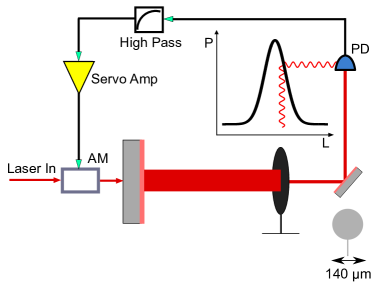
In this paper, we introduce a new feedback control method to lock a movable mirror Fabry-Pérot cavity using radiation pressure. We have implemented this scheme at two independent experiments at LSU and MIT. This scheme relies on the suppression of external disturbances by having a large in-loop optomechanical gain as a result of the large optical spring constant. This suppression, which is mediated via the radiation pressure force, lowers the fluctuations in cavity length and power. A schematic representation of the method is shown in Fig. 1, where the error signal is derived from the transmitted power out of the cavity and is used to control the radiation pressure force acting on the cavity by modulating the intensity of the input laser field passing through an amplitude modulator (AM). An optimal error signal is extracted by passing the transmitted field through a filter. This filter comprises of a gain and a band-pass component. The gain and low-pass filter of the servo controller are to stabilize the anti damping on the optical spring. The high-pass filter is to avoid saturation of the AM actuator due to ambient/seismic fluctuations that are largest at low frequencies (below a few kHz for a typical lab environment). These seismically and acoustically driven fluctuations in cavity length are self-stabilized in the optomechanical dynamics due to the high OM gain at frequencies below optical spring.
II Theoretical Framework
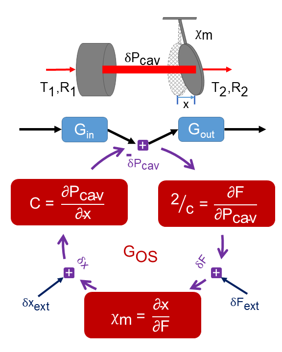
In understanding the noise stabilization of a strong optical spring system with feedback, it is informative to view the optical spring itself as a feedback mechanism. In this view, a closed-loop feedback system is formed between the mechanical oscillator and the optical cavity. The mechanical oscillator, with susceptibility , transduces a force into a displacement. The optical cavity, in turn, transduces the displacement back into a radiation pressure force, forming a closed loop. For simplicity, we consider the frequency dependent susceptibility of a single mechanical resonance at , such that
| (1) |
where is frequency, is the effective mass of the mode of oscillation, with and the mechanical damping and quality factor of the mechanical oscillator, respectively. Note1 .
The open-loop gain pertaining to the cavity’s closed-loop response as shown in Fig. 2 may be given in the limit as NAClosedLoopPaper
| (2) | |||||
where is the intra-cavity power, is the center wavelength of the laser, is the speed of light, T is the total fraction of light leaving the cavity via loss and mirror transmissions, is the half width at half maximum (HWHM) for the cavity optical resonance in rad/s, is the dimensionless detuning of the laser field from the cavity’s resonance, and is the optical spring constant. The optical spring frequency is given by , and its HWHM is . The real part of Eq. 2 corresponds to a position dependent restoring force and the imaginary part corresponds to a velocity dependent anti-damping force Note2 .
The effective susceptibility of the system to a force is then
| (3) | |||||
where is the displacement of the resonator, , is an external force, and in the last step we assume that the and . At frequencies below the optical spring frequency the ambient motion is therefore reduced by the factor
| (4) |
with the approximation assuming . This factor of suppression may be made very large if .
In the limit of a large optical spring frequency, the optical spring provides sufficient stabilization to maintain cavity lock. Due to the negative damping (gain) of the optical spring feedback, however, the system is unstable on its own. This can be seen by writing the closed-loop gain in the s-domain by substituting ,. The closed-loop gain corresponding to this open-loop gain is given by
| (5) | |||||
From the above expression, one can see that this closed-loop gain has at least one right-half-plane pole Note3 and will thus be unstable. This system must be stabilized by an external damping force. The feedback may be localized to frequencies near the optical spring resonance, and its only purpose is to stabilize the unity gain crossing.
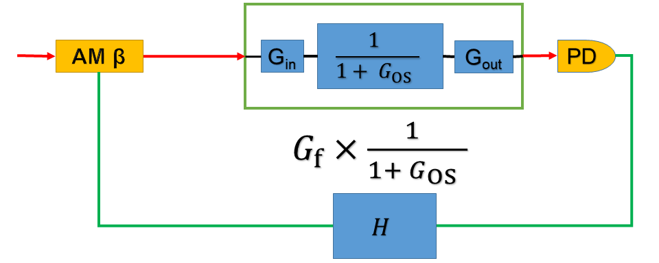
The main purpose of the applied feedback shown in Fig. 3 is to change the shape of the phase response of the system so that the system is stable as well as has good stability margins.
Radiation pressure is a natural transducer to stabilize such a system because there is strong coupling of radiation pressure by assumption. In addition, amplitude modulators have higher response bandwidth than piezoelectric actuators and better range than laser frequency modulation. Furthermore, because these systems are typically operated detuned (within a few line-widths to achieve strong optical springs), the transmitted power through the cavity is a natural readout of the cavity motion.
III Experimental Setup
The schematic shown in Fig. 1 illustrates the experimental setup. The laser field from an NPRO Nd:YAG laser is passed through an amplitude modulator before passing through a half-wave plate and mode-matching lenses en route to the optomechanical cavity. The in-vacuum cavity is 1 cm long and consists of a 0.5-inch (12mm) diameter input mirror with a 1 cm radius of curvature and a microresonator as the second mirror. The input mirror is mounted on a piezoelectric actuator to allow for fine-tuning of the cavity length. The microresonator is fabricated from a stack of crystalline Al0.92Ga0.08As/GaAs layers. It has a diameter of 140 µm and a mass of about 500 ng cole08 ; cole12 ; cole13 ; cole14 ; Singh_PRL . The microresonator has a natural mechanical frequency of Hz and a measured mechanical quality factor , which gives mHz.
The field transmitted through the cavity is detected by a photodetector. The photodetector signal is sent through a high-pass filter and servo controller before being used as the error signal to the amplitude modulator.
IV Results and Discussion
To help understand the feedback mechanisms and individual components of the feedback loops, Fig. 2 and Fig. 3 show the loop diagrams for the feedback loop and the optical spring . Measurements of the open loop gain, plant transfer function, individual loop gains, and closed loop gain are described below.
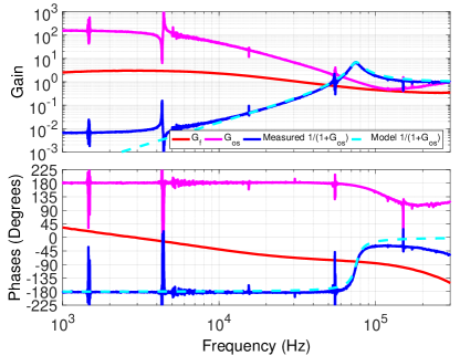
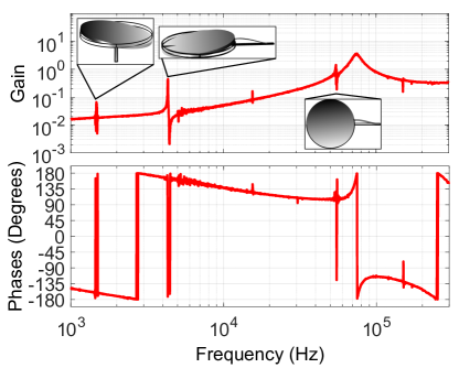
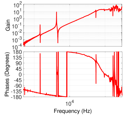
In Fig. 4, the blue curves show the plant transfer function, which is the system we would like to control. We see a peak corresponding to the optical spring at around 75 kHz in the magnitude. Since the system is unstable on its own, the plant transfer function is obtained using the open loop gain measurement with the feedback on. This open loop gain is shown in Fig. 5, and we later divide it by the measured , shown in red in Fig. 4 to obtain the plant transfer function.
Fig. 4 also shows the transfer function of the loop, which is obtained from the open loop transfer function shown in Fig. 5. The large magnitude of at frequencies below the optical spring shows the large suppression that the system’s internal response is providing.
The external electronic feedback loop, , which is used to stabilize the system, is shown in Fig. 4 in the red curves. The measurement of is obtained by measuring the response of individual elements in the loop, which includes the photodetector (PD), the high-pass filter and servo controller (), and the amplitude modulator (), and multiplying them together. The high-pass filter has a corner frequency at 800 Hz and the servo controller has a P-I corner at 100 kHz with a low frequency gain limit of 20 dB. We chose these values to supply sufficient phase margin while also attenuating the feedback at low-frequencies to avoid saturating the AM actuator. The measurement of the elements of is done without using the cavity, so it gives the correct shape of , but does not provide the absolute scaling of the loop because the effect of the cavity is not included. The calibrated is obtained by taking the effect of the cavity into account using the open-loop gain measurement above the optical spring peak where .
Fig. 5 shows the measurement of the open loop gain taken by injecting a signal before (Fig. 3) and measuring the response after PD. Since the measurement enters the loop, the open loop transfer function is given by . The effect of the optical spring is also visible in Fig. 5 with a resonance peak at 75 kHz and a falloff with below the optical spring. There are two unity-gain crossings at 61 kHz and 93 kHz with phases of and . The gain at 250 kHz where the phase crosses has a magnitude of 0.34. Thus, the system is stable with phase margins of and , respectively, and a gain margin of 9.4 dB. We note that while the shown in Fig. 4 does produce a stable system, it is not a unique solution. While other solutions for may be more stable, the we use is simple and achieves our goal of stabilizing the system. We also note that the measurement of deviates from the expected slope above 100 kHz. This is a result of imperfect measurements of the individual components of the loops, which leads to errors in the subtraction for the transfer functions of and .
Another result of the dynamics of the optomechanical system is the reduced response to disturbances at frequencies below the optical spring frequency. Ambient motion causes the cavity length to change by m, while the cavity linewdith is m. It is therefore necessary to suppress the ambient motion in order to operate the cavity. Fig. 4 shows the optical spring resonance at 75 kHz. According to Eq. 4, the ambient motion should be reduced at low frequencies by the factor .
To verify this calculation, we modulate the laser frequency, which in effect, is the same as introducing a disturbance in Fig. 2. Fig. 6 shows a measurement of
| (6) |
taken by modulating the laser frequency and measuring the output of the PD with the change in the laser frequency for a given change in length for the laser piezo. The amount that low-frequency vibrations are reduced by is calculated by taking the ratio of the value of the measurement above the optical spring frequency where the measurement is flat and the value of the measurement at low frequencies, yielding a suppression of at least 50,000.
The response of the system to an external force is
| (7) |
V Conclusion
In conclusion, we have demonstrated a stable feedback control method to lock a moveable mirror Fabry-Pérot cavity using radiation pressure. In this scheme, the use of radiation pressure as an actuator provides a large locking bandwidth compared to a piezoelectric device used in the simple “side of fringe” locking. We have experimentally shown that the system is stable and reduces low-frequency disturbances by a factor of at least 50,000. The combination of the stable system and excellent low-frequency noise suppression allows the optomechanical cavity to be operated on time scales of hours to days without losing lock. With the low-frequency noise reduced, we aim to measure broadband quantum radiation pressure noise and ponderomotive squeezing at frequencies relevant to Advanced LIGO. In addition, since the quadrature of the field inside the cavity is actually rotated with respect to the input field, the feedback gain could be increased by modulating in a different quadrature. A modulation in an arbitrary quadrature can be achieved by stitching together two amplitude modulator crystals and adding a relative drive between them UTM . This configuration could be useful if the negative damping is too high to be compensated with a single amplitude modulator.
Acknowledgements.
This work was supported by the National Science Foundation CAREER grant PHY-1150531, as well as PHY-1707840 and PHY-1404245. MY and DM receive support from the Australian Research Council through project number CE170100004 (OzGrav). This document has been assigned the LIGO document number LIGO-P1700100. NA would like to thank Slawomir Gras and Aaron Buikema for valuable discussions and suggestions.References
- (1) M. Aspelmeyer, T. J. Kippenberg, and F. Marquardt, “Cavity optomechanics,” Rev. Mod. Phys., vol. 86, pp. 1391–1452, Dec 2014.
- (2) V. B. Braginsky and I. I. Minakova, “Influence of the small displacement measurements on the dynamical properties of mechanical oscillating systems,” Moscow Univ. Phys. Bull., vol. 1, pp. 83–85, 1964.
- (3) V. B. Braginsky and A. B. Manukin, “Ponderomotive effects of electromagnetic radiation,” Soviet Physics JETP, vol. 25, pp. 653–655, 1967.
- (4) V. Braginsky, M. Gorodetsky, and F. Khalili, “Optical bars in gravitational wave antennas,” Physics Letters A, vol. 232, no. 5, pp. 340 – 348, 1997.
- (5) A. Buonanno and Y. Chen, “Laser-interferometer gravitational-wave optical-spring detectors,” Classical and Quantum Gravity, vol. 19, no. 7, p. 1569, 2002.
- (6) J. Harms, Y. Chen, S. Chelkowski, A. Franzen, H. Vahlbruch, K. Danzmann, and R. Schnabel, “Squeezed-input, optical-spring, signal-recycled gravitational-wave detectors,” Phys. Rev. D, vol. 68, p. 042001, Aug 2003.
- (7) B. S. Sheard, M. B. Gray, C. M. Mow-Lowry, D. E. McClelland, and S. E. Whitcomb, “Observation and characterization of an optical spring,” Phys. Rev. A, vol. 69, p. 051801, May 2004.
- (8) T. Corbitt, D. Ottaway, E. Innerhofer, J. Pelc, and N. Mavalvala, “Measurement of radiation-pressure-induced optomechanical dynamics in a suspended fabry-perot cavity,” Phys. Rev. A, vol. 74, p. 021802, Aug 2006.
- (9) T. J. Kippenberg, H. Rokhsari, T. Carmon, A. Scherer, and K. J. Vahala, “Analysis of radiation-pressure induced mechanical oscillation of an optical microcavity,” Phys. Rev. Lett., vol. 95, p. 033901, Jul 2005.
- (10) T. Corbitt, Y. Chen, E. Innerhofer, H. Müller-Ebhardt, D. Ottaway, H. Rehbein, D. Sigg, S. Whitcomb, C. Wipf, and N. Mavalvala, “An all-optical trap for a gram-scale mirror,” Phys. Rev. Lett., vol. 98, p. 150802, Apr 2007.
- (11) D. Kelley, J. Lough, F. Mangaña-Sandoval, A. Perreca, and S. W. Ballmer, “Observation of photothermal feedback in a stable dual-carrier optical spring,” Phys. Rev. D, vol. 92, p. 062003, Sep 2015.
- (12) A. Sawadsky, H. Kaufer, R. M. Nia, S. P. Tarabrin, F. Y. Khalili, K. Hammerer, and R. Schnabel, “Observation of generalized optomechanical coupling and cooling on cavity resonance,” Phys. Rev. Lett., vol. 114, p. 043601, Jan 2015.
- (13) M. Hossein-Zadeh and K. J. Vahala, “Observation of optical spring effect in a microtoroidal optomechanical resonator,” Opt. Lett., vol. 32, pp. 1611–1613, Jun 2007.
- (14) M. P. Edgar, J. Macarthur, B. W. Barr, S. Hild, S. Huttner, B. Sorazu, and K. A. Strain, “Demonstration of an optical spring in the 100 g mirror regime,” Classical and Quantum Gravity, vol. 33, no. 7, p. 075007, 2016.
- (15) N. A. Gordon, B. W. Barr, A. Bell, C. Graef, S. Hild, S. H. Huttner, S. S. Leavey, J. Macarthur, B. Sorazu, J. Wright, and K. A. Strain, “Experimental demonstration of coupled optical springs,” Classical and Quantum Gravity, vol. 34, no. 3, p. 035020, 2017.
- (16) R. Singh, G. D. Cole, J. Cripe, and T. Corbitt, “Stable optical trap from a single optical field utilizing birefringence,” Phys. Rev. Lett., vol. 117, p. 213604, Nov 2016.
- (17) C. H. Metzger and K. Karrai, “Cavity cooling of a microlever,” Nature, vol. 432, pp. 1002–1005, Dec 2004.
- (18) A. Naik, O. Buu, M. D. LaHaye, A. D. Armour, A. A. Clerk, M. P. Blencowe, and K. C. Schwab, “Cooling a nanomechanical resonator with quantum back-action,” Nature, vol. 443, pp. 193–196, Sep 2006.
- (19) S. Gigan, H. R. Bohm, M. Paternostro, F. Blaser, G. Langer, J. B. Hertzberg, K. C. Schwab, D. Bauerle, M. Aspelmeyer, and A. Zeilinger, “Self-cooling of a micromirror by radiation pressure,” Nature, vol. 444, pp. 67–70, Nov 2006.
- (20) D. Kleckner and D. Bouwmeester, “Sub-kelvin optical cooling of a micromechanical resonator,” Nature, vol. 444, pp. 75–78, Nov 2006.
- (21) O. Arcizet, P.-F. Cohadon, T. Briant, M. Pinard, and A. Heidmann, “Radiation-pressure cooling and optomechanical instability of a micromirror,” Nature, vol. 444, pp. 71–74, Nov 2006.
- (22) A. Schliesser, P. Del’Haye, N. Nooshi, K. J. Vahala, and T. J. Kippenberg, “Radiation pressure cooling of a micromechanical oscillator using dynamical backaction,” Phys. Rev. Lett., vol. 97, p. 243905, Dec 2006.
- (23) S. Mancini, D. Vitali, and P. Tombesi, “Optomechanical cooling of a macroscopic oscillator by homodyne feedback,” Phys. Rev. Lett., vol. 80, pp. 688–691, Jan 1998.
- (24) T. Corbitt, C. Wipf, T. Bodiya, D. Ottaway, D. Sigg, N. Smith, S. Whitcomb, and N. Mavalvala, “Optical dilution and feedback cooling of a gram-scale oscillator to 6.9 mk,” Phys. Rev. Lett., vol. 99, p. 160801, Oct 2007.
- (25) C. M. Mow-Lowry, A. J. Mullavey, S. Goßler, M. B. Gray, and D. E. McClelland, “Cooling of a gram-scale cantilever flexure to 70 mk with a servo-modified optical spring,” Phys. Rev. Lett., vol. 100, p. 010801, Jan 2008.
- (26) B. J. Meers, “Recycling in laser-interferometric gravitational-wave detectors,” Phys. Rev. D, vol. 38, pp. 2317–2326, Oct 1988.
- (27) G. Heinzel, K. A. Strain, J. Mizuno, K. D. Skeldon, B. Willke, W. Winkler, R. Schilling, A. Rüdiger, and K. Danzmann, “Experimental demonstration of a suspended dual recycling interferometer for gravitational wave detection,” Phys. Rev. Lett., vol. 81, pp. 5493–5496, Dec 1998.
- (28) A. Buonanno and Y. Chen, “Signal recycled laser-interferometer gravitational-wave detectors as optical springs,” Phys. Rev. D, vol. 65, p. 042001, Jan 2002.
- (29) P. Verlot, A. Tavernarakis, T. Briant, P.-F. Cohadon, and A. Heidmann, “Backaction amplification and quantum limits in optomechanical measurements,” Phys. Rev. Lett., vol. 104, p. 133602, Mar 2010.
- (30) J. Mizuno, K. Strain, P. Nelson, J. Chen, R. Schilling, A. Rüdiger, W. Winkler, and K. Danzmann, “Resonant sideband extraction: a new configuration for interferometric gravitational wave detectors,” Physics Letters A, vol. 175, no. 5, pp. 273 – 276, 1993.
- (31) G. Heinzel, J. Mizuno, R. Schilling, W. Winkler, A. Rüdiger, and K. Danzmann, “An experimental demonstration of resonant sideband extraction for laser-interferometric gravitational wave detectors,” Physics Letters A, vol. 217, no. 6, pp. 305 – 314, 1996.
- (32) B. J. Meers, A. Krolak, and J. A. Lobo, “Dynamically tuned interferometers for the observation of gravitational waves from coalescing compact binaries,” Phys. Rev. D, vol. 47, pp. 2184–2197, Mar 1993.
- (33) D. A. Simakov, “Time-domain analysis of a dynamically tuned signal recycled interferometer for the detection of chirp gravitational waves from coalescing compact binaries,” Phys. Rev. D, vol. 90, p. 102003, Nov 2014.
- (34) C. Affeldt, K. Danzmann, K. L. Dooley, H. Grote, M. Hewitson, S. Hild, J. Hough, J. Leong, H. Lück, M. Prijatelj, S. Rowan, A. Rüdiger, R. Schilling, R. Schnabel, E. Schreiber, B. Sorazu, K. A. Strain, H. Vahlbruch, B. Willke, W. Winkler, and H. Wittel, “Advanced techniques in geo 600,” Classical and Quantum Gravity, vol. 31, no. 22, p. 224002, 2014.
- (35) J. A. et al., “Advanced ligo,” Classical and Quantum Gravity, vol. 32, no. 7, p. 074001, 2015.
- (36) F. A. et al., “Advanced virgo: a second-generation interferometric gravitational wave detector,” Classical and Quantum Gravity, vol. 32, no. 2, p. 024001, 2015.
- (37) K. Somiya, “Detector configuration of kagra–the japanese cryogenic gravitational-wave detector,” Classical and Quantum Gravity, vol. 29, no. 12, p. 124007, 2012.
- (38) T. Corbitt, Y. Chen, F. Khalili, D. Ottaway, S. Vyatchanin, S. Whitcomb, and N. Mavalvala, “Squeezed-state source using radiation-pressure-induced rigidity,” Phys. Rev. A, vol. 73, p. 023801, Feb 2006.
- (39) O. Miyakawa, R. Ward, R. Adhikari, M. Evans, B. Abbott, R. Bork, D. Busby, J. Heefner, A. Ivanov, M. Smith, R. Taylor, S. Vass, A. Weinstein, M. Varvella, S. Kawamura, F. Kawazoe, S. Sakata, and C. Mow-Lowry, “Measurement of optical response of a detuned resonant sideband extraction gravitational wave detector,” Phys. Rev. D, vol. 74, p. 022001, Jul 2006.
- (40) A more realistic form including multiple resonances could be used instead, but the single resonance susceptibility works well for this analysis. This is because the higher-order modes have a larger effective mass than the fundamental mode due to their poor overlap with the cavity mode and hence don’t contribute much to the broadband behavior.
- (41) N. Aggarwal and N. Mavalvala, “Closed loop response of an optomechanical cavity using classical physics,” In Preparation.
- (42) This force will be anti-restoring and damping for a red detuned laser.
- (43) the terms in the denominator are not all of the same sign.
- (44) G. D. Cole, S. Gröblacher, K. Gugler, S. Gigan, and M. Aspelmeyer, “Monocrystalline AlxGa1-xAs heterostructures for high-reflectivity high-q micromechanical resonators in the megahertz regime,” Applied Physics Letters, vol. 92, no. 26, p. 261108, 2008.
- (45) G. D. Cole, “Cavity optomechanics with low-noise crystalline mirrors,” in Proc. SPIE 8458, Optics & Photonics, Optical Trapping and Optical Micromanipulation IX, p. 845807, SPIE, August 2012.
- (46) G. D. Cole, W. Zhang, M. J. Martin, J. Ye, and M. Aspelmeyer, “Tenfold reduction of brownian noise in high-reflectivity optical coatings,” Nat Photon, vol. 7, pp. 644–650, Aug. 2013.
- (47) G. D. Cole, W. Zhang, B. J. Bjork, D. Follman, P. Heu, C. Deutsch, L. Sonderhouse, J. Robinson, C. Franz, A. Alexandrovski, M. Notcutt, O. H. Heckl, J. Ye, and M. Aspelmeyer, “High-performance near- and mid-infrared crystalline coatings,” Optica, vol. 3, pp. 647–656, Jun 2016.
- (48) W. Yam, E. Davis, S. Ackley, M. Evans, and N. Mavalvala, “Continuously tunable modulation scheme for precision control of optical cavities with variable detuning,” Opt. Lett., vol. 40, pp. 3675–3678, Aug 2015.