Circular and linear magnetic quantum ratchet effects in dual-grating-gate CdTe-based nanostructures
Abstract
We report on the observation and systematic study of polarization sensitive magnetic quantum ratchet effects induced by alternating electric fields in the terahertz frequency range. The effects are detected in (Cd,Mn)Te-based quantum well (QW) structures with inter-digitated dual-grating-gate (DGG) lateral superlattices. A electric current excited by cw terahertz laser radiation shows -periodic oscillations with an amplitude much larger than the photocurrent at zero magnetic field. Variation of gate voltages applied to individual grating gates of the DGG enables us to change the degree and the sign of the lateral asymmetry in a controllable way. The data reveal that the photocurrent reflects the degree of lateral asymmetry induced by different gate potentials. We show that the magnetic ratchet photocurrent includes the Seebeck thermoratchet effect as well as the effects of “linear” and “circular” ratchets, which are sensitive to the corresponding polarization of the driving electromagnetic force. Theoretical analysis performed in the framework of semiclassical approach and taking into account Landau quantization describes the experimental results well.
pacs:
73.21.Fg, 78.67.De, 73.63.HsI Introduction
Classical and quantum ratchets are spatially noncentrosymmetric systems which are able to transport classical or quantum particles in the absence of an average macroscopic force, for reviews see e.g. Refs. prost97 ; reimann ; hanggi ; Denisovhanggi . In semiconductors and semiconductor nanostructures, driving the system out of thermal equilibrium, e.g. by high frequency alternating electric field, causes a electric current. The required lack of inversion symmetry can be fulfilled either by making use of an built-in asymmetry induced by the crystallographic structure (in this case the ratchet effects are called photogalvanic effects) or by artificial lateral superlattices superimposed on typically two-dimensional semiconductor materials. Such superlattices have been realized in a great variety of forms which allow one to explore the origin of ratchet effects buttiker ; buttiker2 ; grifoni ; kotthaus ; samuelson ; Chepel ; Chepelianskii ; Kvon ; Olbrich_PRL_09 ; Popov2010 ; Olbrich_PRB_11 ; Review_JETP_Lett ; KannanPortal12 ; Nalitov ; PopovAPL2013 ; Rozhansky2015 ; PopovIvchenko ; ratchet_graphene ; PRB2017 as well as to apply them to detect terahertz radiation otsuji ; det2 ; otsuji2 ; Popov_Otsuji_Knap . The latter, besides high sensitivity and short response times, offers new functionalities being a good candidate for all-electric detection of the radiation polarization state including radiation helicity being so far realized applying photogalvanics in QW structures ellipticitydetector ; ellipticitydetector2 and HEMT structures ellipticitydetector3 ; Otsuji_Ganichev .
Most recently it has been demonstrated that application of an external magnetic field to QW structures with DGG lateral superlattices results in -periodic oscillations of the electric ratchet current with an amplitude much larger than the current at zero magnetic field PRB2017 ; JETP_Lett_review . The terahertz radiation induced magnetic ratchet current reported in Ref. PRB2017 has been shown to be caused by the Seebeck ratchet (or thermoratchet) effect, so far detected in zero magnetic field only Review_JETP_Lett . It stems from the combined effect of radiation-induced inhomogeneous heating of the two-dimensional electron gas and the grating-induced electrostatic electron potential , where is the in-plane coordinate in the direction perpendicular to the DGG metallic stripes. The inhomogeneous heating is caused by the near-field space modulation of the electric field of the radiation. The coordinate dependent field acts on the electron gas changing the local effective electron temperature to , where is the equilibrium temperature. The inhomogeneous heating causes the diffusion of electrons from warmer to colder regions and forms a nonequilibrium electron density profile . In short, the Seebeck ratchet current is a drift of the nonequilibrium correction in the electric field of the space modulated electrostatic potential. The Seebeck ratchet current is insensitive to the radiation polarization state and, in the presence of quantizing magnetic field, follows the -periodic oscillations of the longitudinal resistance.
Here we report on the observation and study of polarization sensitive magnetic quantum ratchet effects driven by linearly polarized radiation (linear magnetic ratchet effect) or/and by the radiation helicity (circular magnetic ratchet effect). These effects are demonstrated for (Cd,Mn)Te/(Cd,Mg)Te diluted magnetic heterostructures with superimposed lateral asymmetric superlattices. Similarly to the magnetic thermoratchet effect, applying a magnetic field along the growth direction we have observed that the polarization sensitive magnetic ratchet currents exhibit sign-alternating -periodic oscillations with amplitudes substantially larger than the ratchet signal at zero magnetic field. In contrast to the thermoratchet the mechanisms of these ratchet effects are unrelated to electron-gas heating. They arise from the phase shift between the periodic electrostatic potential and the periodic radiation field resulting from near field diffraction. The ratchet currents are determined by the in-plane orientation of the electric field vector (linear magnetic ratchet effect) or by the radiation helicity (circular magnetic ratchet effect). They appear because the carriers in the laterally modulated quantum wells move in both in-plane directions and are subjected to the action of the two-component electric field . Theoretical analysis, considering the magnetic quantum ratchet effect in the framework of semiclassical approach JETP_Lett_review ; PRB2017 ; Budkin_Golub , describes the experimental results well. It shows that the observed magneto-oscillations with enhanced photocurrent amplitude result from Landau quantization. Furthermore, for (Cd,Mn)Te at low temperatures, the oscillations are affected by the exchange enhanced Zeeman splitting in diluted magnetic heterostructures.
The paper is organized as follows. In Sec. II we describe the investigated samples, the experimental technique and results for zero magnetic field. In Sec. III we discuss the results on magnetic ratchet effects generated by linearly/circularly polarized THz radiation. In the following Sec. IV and Sec. V we present the theory and compare its results with the experimental data. Finally, we summarize the results and give an outlook for future studies of the ratchet effects (Sec. VI).
II Samples, experimental technique and photocurrents at zero magnetic field
II.1 Quantum well structures
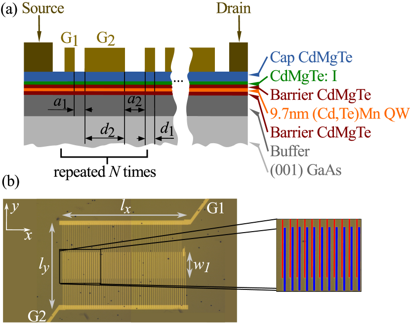
Ratchet currents have been studied in (Cd,Mn)Te/CdMgTe QW structures with doubly inter-digitated grating gates (DGG) G1 and G2. The cross-section of the structure, a sketch and a microphotograph of DGG are shown in Fig. 1. Structures have been grown by molecular beam epitaxy on (001)-oriented GaAs substrates Crooker ; Egues ; Jaroszynski2002 ; DMSPRL09 . We used a QW of 9.7 nm width with Cd0.76Mg0.24Te alloy as a barrier material. The samples are modulation doped with Iodine donors introduced into the top barrier at 10 nm distance from the QW. Doped region has been overgrown by a 50 nm Cd0.76Mg0.24Te undoped cap layer. Two evenly spaced Cd1-xMnxTe thin layers were inserted during the QW growth applying the digital alloy technique Kneip2006 . Incorporation of Mn atoms into the QW region leads to a strong enhancement of the effective -factor of band carriers, and hence to an enhanced Zeeman splitting. Analysis of the magneto-photoluminescence data DMSPRL09 obtained on the samples made from the same wafer as used in the current study have shown that the spin splitting is well described by the modified Brillouin function Gaj79 ; Fur88 by using the effective average concentration of Mn in the digital alloy = 0.015. The samples have also been characterized by electrical transport measurements. At low temperatures pronounced Shubnikov-de-Haas (SdH) oscillations and well resolved quantum Hall plateaus have been observed, see Fig. 2. The density of the two-dimensional electron gas, , and the electron mobility, , determined at liquid helium temperature (4.2 K) are cm-2 and cm2/Vs. More details on structures characteristics can be found in Ref. PRB2017 .

II.2 Inter-digitated dual-grating-gate structures
The DGG are formed by electron beam lithography, followed by deposition of 25 nm-thick gold films and subsequent lift-off. The grating-gate supercell consists of two metal stripes having widths m and m, see Fig. 1. The corresponding spacings in sample #A (sample #B) are m (m) and m (m). The supercell is repeated times to produce a lateral asymmetric superlattice with the period m, see Refs. Olbrich_PRB_11 ; ratchet_graphene ; staab2015 . All narrow (top gate G1) and wide (top gate G2) grating stripes have been connected by additional gold bars [wide horizontal lines in Fig. 1(b)] so that wide and narrow gate stripes can be biased independently, see inset in Fig. 3. The distance between the connecting bars is m and the length m. The width of the area with both gates present is m, see Fig. 1(b). The size of the complete DGG structure is about m2.
Two pairs of ohmic contacts have been prepared to measure the photocurrent perpendicularly to the metal stripes (, -direction) and parallel to them (, -direction), see inset in Fig. 3. Same contact pairs have been used for magneto-transport measurements accompanying the measurement of magnetic field induced photocurrent. The samples were placed into an optical cryostat with -cut crystal quartz windows and superconducting magnet. The magnetic field up to 7 T could be applied normal to the QW plane.
Magneto-transport measurements show that the application of gate voltages to individual gates does not visibly influence the period of -periodic oscillations of the longitudinal resistance, . This is due to the fact that the area of DGG fingers is a very small fraction of the whole sample area. Note, that while the overall transport characteristics obtained at different cooldowns is the same the value of the effective gate voltages acting on the electrons in 2DEG may change by V.
II.3 Methods
The photocurrents are generated in samples cooled down to liquid helium temperature applying THz radiation of a continuous wave (cw) molecular optically pumped laser Ganichev93 ; Kvon2008 ; Kohda2012 operating at frequency THz (photon energy meV, wavelength m). The radiation photon energy is smaller than the band gap as well as the size-quantized subband separation. Thus, the radiation induces only indirect (Drude-like) optical transitions in the lowest conduction subband (Drude-like free carrier absorption). The measurements of magnetic-field-induced photocurrents are carried out under excitation of the (001)-grown QW samples with polarized terahertz radiation at normal incidence. This experimental geometry is chosen to exclude any effects in the area outside the DGG structure known to cause photocurrents at zero magnetic field and for magnetic field normal to the QW plane Review_JETP_Lett ; PRB2017 . Measurements applying a pyroelectric camera Ganichev1999 ; Schneider04 have shown that the spatial beam distribution has an almost Gaussian profile with a beam spot on the sample of about mm diameter.
The incident power about 30 mW is modulated at about 75 Hz by an optical chopper. Taking into account sizes of the superlattice and the beam spot we obtain that the power irradiating the structure is mW. The photoresponse is measured in unbiased samples by the voltage drop across a load resistor Ohm using standard lock-in technique. The benefit of using of the small value of , where is the sample resistance, is that the detected signal is unaffected by the sample resistance variation and is just proportional to the electric current generated by the THz radiation. The current is calculated via .
The laser radiation is initially linearly polarized along the -axis. To explore the polarization dependence of the ratchet effect we used crystal quartz plate as well as one-dimensional metal mesh polarizers book . To vary the azimuthal angle of linearly polarized radiation we rotated the mesh polarizer placed behind the plate providing a circularly polarized radiation. The angle is defined as an angle between radiation electric field vector and direction , which is perpendicular to the metal stripes. To study the helicity dependence of the signal the plate was rotated by an angle between the laser polarization plane and the optical axis of the plate. In this geometry, the radiation helicity is varied as . Note that for and as well for radiation is linearly polarized.
II.4 Photocurrent at zero magnetic field
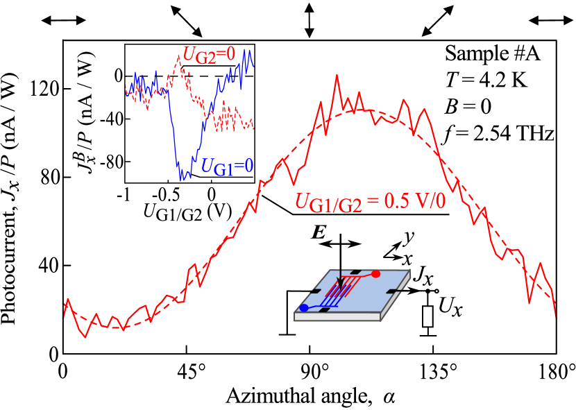
We start with the description of the results obtained for sample #A excited by linearly polarized radiation at zero magnetic field. Illuminating the DGG by normally incident radiation we detect the photocurrent and measured in directions normal and parallel to the DGG stripes, respectively. The current vanishes for a beam shifted to the unpatterned area. This is in agreement with the discussion above underlining that due to symmetry arguments photocurrents can not be generated in unpatterned structures, as was also observed in previous results obtained on the same (001)-grown (Cd,Mn)Te/CdMgTe QW structures (sample #A in Ref. PRB2017 ). The overall behavior of both and photocurrents is very similar but the magnitude of the photocurrent in -direction is about 2 to 10 times smaller as that in the -direction. Therefore, for this sample we present the data for , only. As shown in Fig. 3, the current consists of the polarization independent contribution and contributions varying upon rotation of the radiation electric field vector defined by the azimuthal angle . The overall polarization dependence can be well fitted by
| (1) |
where , , and are fitting parameters. We note, that and represent the Stokes parameters and describe the degree of linear polarization in the coordinate axes and within the system rotated about an angle of 45∘, respectively Stokes1 ; BelkovJPCM . The fact that the photocurrent is detected at normal incidence of patterned structure indicates that the photocurrent is caused by the ratchet effect.
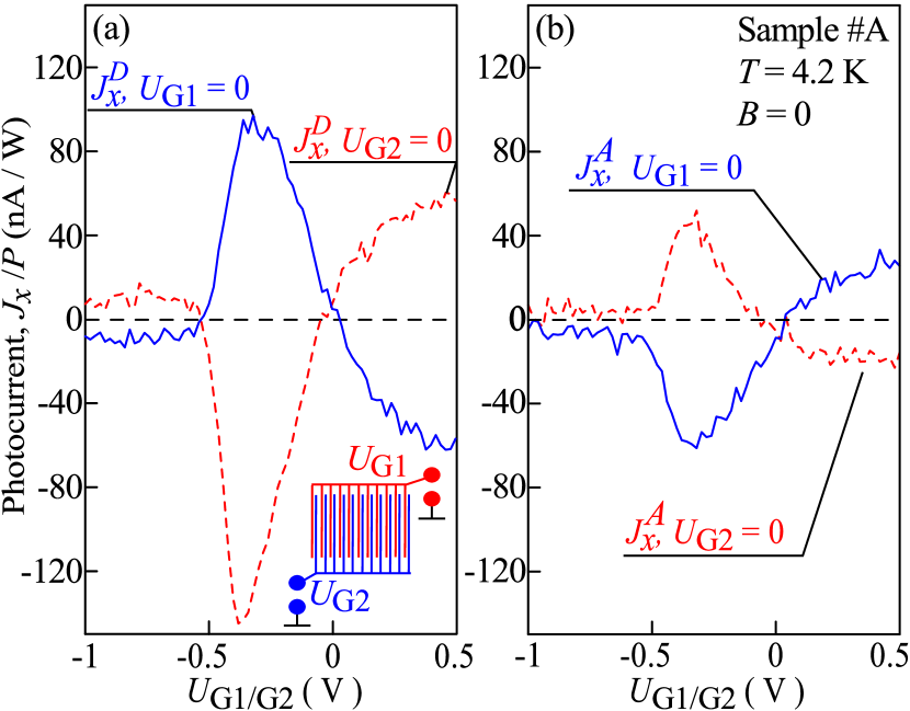
An ultimate proof for ratchet effect as a cause of the photocurrent, however, comes from the experiments applying different gate voltages to the DGG subgates. The ratchet effects are obviously expected to be strongly dependent on the in-plane asymmetry of the electrostatic potential being proportional to the averaged product Review_JETP_Lett ,
| (2) |
of the derivative of the coordinate dependent electrostatic potential and the distribution of the electric near-field Review_JETP_Lett ; Nalitov ; PopovAPL2013 ; PopovIvchenko . In the following, we call the parameter the lateral asymmetry. The value of may change sign depending on electrostatic potential . Consequently a variation of individual gate voltages should result in a change of the ratchet current including reversal of its direction. Sweeping one subgate bias voltage, e.g. , from negative to positive and holding another one at zero should cause the sign inversion of the ratchet current. Exactly this behavior has been observed in the experiment for all three contributions, see the inset in Fig. 3 and Fig. 4. Furthermore, reversing the circuit in the way that now is swept and causes the reversal of the photocurrent direction, see Fig. 3. Note that for unbiased gates a non-zero built-in electrostatic potential is formed due to the presence of metal stripes in the vicinity of QW.
We also note that proportionality of the observed current to the lateral asymmetry parameter demonstrates that a possible contribution due to edge photogalvanic effects, similar to the polarization-sensitive photocurrents in graphene flakes Karch_PRL_2011 ; Glazov2014 , plays no essential role in the described experiments.
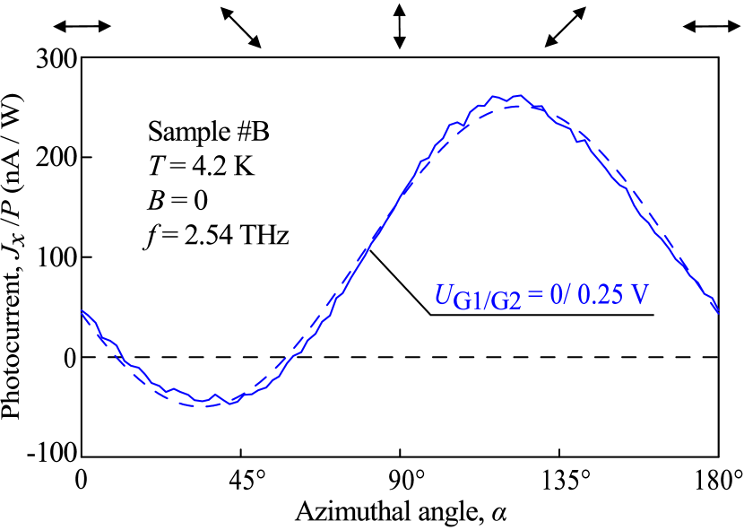
Figures 3 and 4 reveal that in sample #A the dominating contribution to the total photocurrent comes from the polarization independent current , being previously shown to be caused by the Seebeck ratchet PRB2017 . Nevertheless polarization dependent photocurrent contributions and are clearly detected in this sample for almost all combinations of the gate voltage. First of all we emphasize that the polarization dependence can not be simply attributed to the Seebeck ratchet effect changing its magnitude due to the change of the radiation reflection from the DGG. The latter would results in a signal maximum for the radiation electric field aligned perpendicularly to the grating’s stripes (), whereas in experiment we observed just the opposite behavior: the maximum signal is achieved for electric field parallel to the stripes in -direction (), see Fig. 3. A more direct prove for the existence of the polarization dependent photocurrents is detected in sample #B with the larger gates spacing . In this sample for a certain combination of gate voltages we detected change of the photocurrent sign upon variation of the azimuthal angle: the fact clearly demonstrating contribution of an origin different from the Seebeck ratchet, see Fig. 5. While polarization dependent photocurrents ( and ) for CdTe-based QWs at zero magnetic field are reported here for the first time they have been detected and discussed in details for other materials (GaAs QWs, InAlAs/InGaAs/InAlAs/InP HEMT and graphene) in Refs. Olbrich_PRL_09 ; Olbrich_PRB_11 ; Review_JETP_Lett ; Nalitov ; ratchet_graphene . The present work is focused on the polarization dependent magnetic ratchet currents, therefore, a deeper analysis of the results for zero magnetic field is out of its scope.
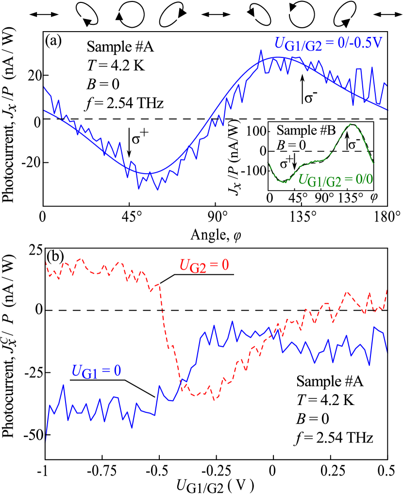
Previous studies of ratchet effects in other materials (for review see Ref. Review_JETP_Lett ) demonstrated that beside the photocurrents addressed above a contribution proportional to the radiation helicity may also exist. This contribution we also detected for (Cd,Mn)Te/CdMgTe QW samples. Figure 6(a) shows photocurrent as a function of the phase angle . This dependence is measured for subgate voltages , V for which contributions proportional to coefficients , , and are strongly suppressed, see the inset in Fig. 3 and Fig. 4. The data can be well fitted by
where is a fitting parameter for the contribution proportional to the degree of circular polarization , i.e. the fourth Stokes parameter Stokes1 ; BelkovJPCM . Sweeping either or gate voltages we have proved that helicity driven photocurrent is as well proportional to the degree of the electrostatic potential asymmetry. This is shown in Fig. 6(b). Note that in contrast to the currents obtained for linearly polarized light the gate dependencies for , and , are not symmetric with respect to the abscissa. We also note that, like the polarization independent contribution, the curves and cross each other not only near zero-bias values but also for rather high negative voltages.
Similar results have been obtained for sample #B. An example of the helicity dependence measured in this sample for or is shown in the inset in Fig. 6(a). It shows that in this sample the data are also well fitted by Eq. (II.4). It should be noted that the ratchet current can be detected even for gate voltages applied to both gates. As addressed above for unbiased gates, the required lateral asymmetry comes from a non-zero built-in electrostatic potential which is formed due to the presence of metal stripes in the QW vicinity. This potential is shown to be particularly large in sample #B.
To summarize this part, the measurements for zero magnetic field show that excitation of DGG CdTe-based superlattices by THz radiation results in polarization independent and three polarization dependent ratchet photocurrents which can efficiently be controlled by voltages applied to individual subgates. The overall behavior of the photocurrents is in qualitative agreement with that of the electronic ratchet effects observed in semiconductor QW structures and graphene with a lateral superlattice and these ratchet effects can well described by the microscopic theory developed in Refs. Olbrich_PRL_09 ; Olbrich_PRB_11 ; Review_JETP_Lett ; ratchet_graphene .
III Magnetic field induced photocurrent
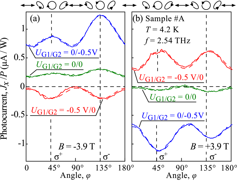
Now we turn to the main part of the paper devoted to polarization dependent magnetic quantum ratchet effects. Applying magnetic field normal to the QW plane we observed that the photocurrent increases drastically and, at high magnetic fields, exhibits sign-alternating -periodic oscillations. This is shown in Fig. 7(a) for linearly polarized radiation with electric field vector oriented normal to the DGG stripes. This figure also reveals that reversal of lateral asymmetry of the electrostatic potential causes the sign change of the photocurrent oscillations. Note that the positions of oscillation maxima/minima remain unchanged for all potentials used in our study of the sample.
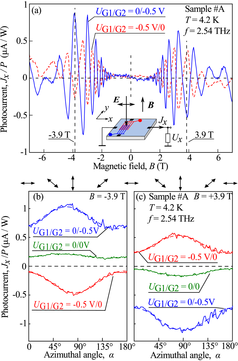
Rotation of the electric field orientation results in a variation of the photocurrent magnitude. This is shown in Figs. 7(b) and (c) for two magnetic field strengths corresponding to peaks of magneto-oscillations [see vertical dashed lines in panel (a)]. The overall polarization dependence of the photocurrent can be well fitted by Eq. (1) with fitting parameters , and which now depend on the magnitude and sign of the external magnetic field. Figures 7(b) and (c) show that in sample #A the polarization independent photocurrent provides a dominant contribution. This photocurrent has been studied and discussed in details in Ref. PRB2017 . It has been shown to be caused by the Seebeck magnetic quantum ratchet effect and will be not discussed here. Our present study is focused on polarization dependent parts.
Figures 7(b) and (c) reveal that, similarly to the polarization independent Seebeck magnetic quantum ratchet effect, polarization dependent parts change the sign upon reversal of the lateral electrostatic potential, see the curves for V/0 and V. This observation provides an evidence that the polarization dependent part of the photocurrent is also driven by the ratchet effect. Due to a large contribution of the detected for sample #A the variation of the electric field orientation causes only the modulation of the photocurrent magnitude.
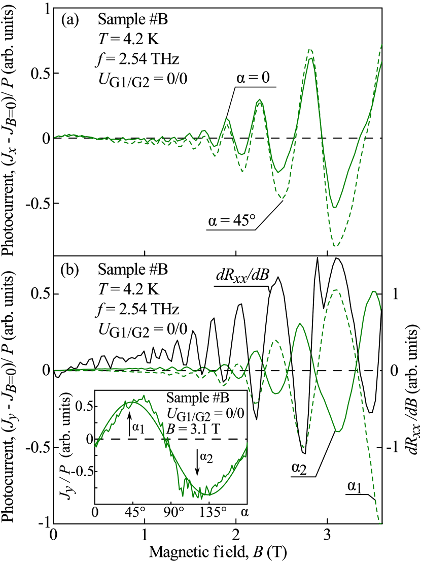
In contrast to sample #A, in sample #B with the larger spacing we have observed that relative contribution of is substantially diminished for the photocurrent measured in the -direction. Moreover, the magnitudes of the contributions and are comparable in this sample. In the direction perpendicular to the DGG stripes of sample #B photocurrent is dominated by the polarization independent magnetic Seebeck ratchet effect and the variation of the angle only slightly affects the oscillation magnitudes without changing their sign, see Fig. 8(a). For the -direction, however, changing of the angle results in the sign change of the photocurrent revealing a dominating contribution of the polarization dependent photocurrent, see Fig. 8(b) and inset in this panel. Here and in the remaining plots a small contribution of the zero magnetic field photocurrent, , is subtracted from the total current. Polarization dependence of obtained for one of the peaks of magneto-oscillations [see vertical dashed line in panel (b)] demonstrates that in the structure #B with zero applied voltages the polarization independent current is almost negligible and the photocurrent is dominated by the contribution proportional to the coefficient . Figure 8(b) also reveals that magneto-oscillations measured for angles and indicated by vertical arrows in the inset have opposite signs for all peaks.
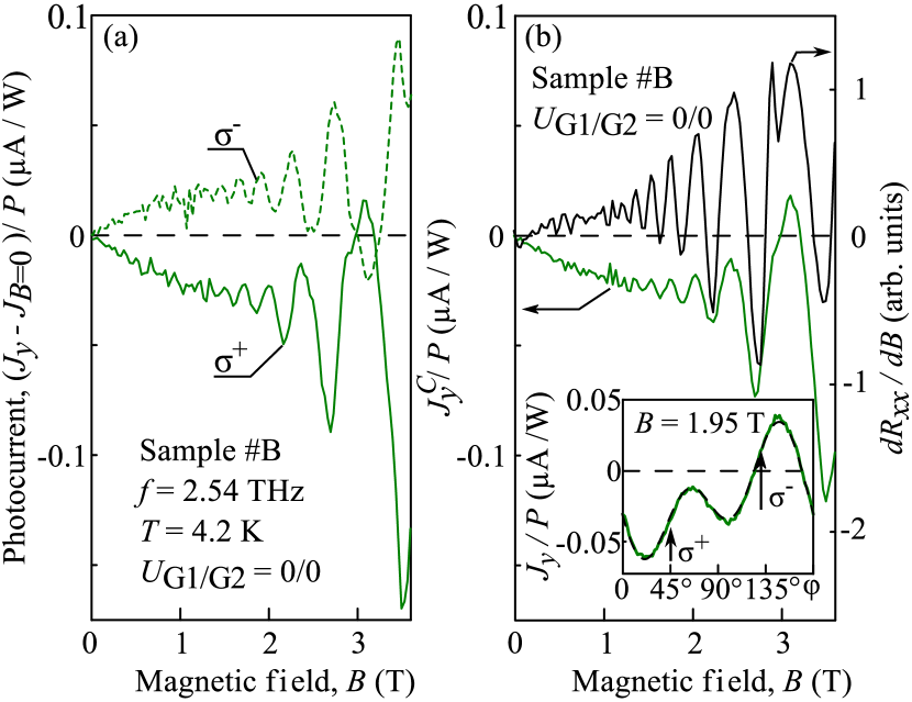
At last but not at least we discuss the helicity driven magnetic photocurrents. While the influence of the radiation helicity on magnetic quantum ratchets has been detected in both samples, similarly to the linear magnetic quantum ratchet, it is most pronounced in sample #B and the -direction. Therefore, here we focus on these data, and the results on sample #A are presented in the Appendix A. Figure 9(a) shows magnetic field dependencies of the photocurrents measured for right- and left-handed polarized radiation in directions parallel to the DGG stripes. The figure reveals that magneto-oscillations have opposite sign for opposite helicities. The overall polarization dependence obtained by variation of the phase angle can be well fitted by Eq. (II.4) with magnetic field dependent coefficients , see inset in Fig. 9(b). For purely right and left handed circular polarization, the terms proportional to and in Eq. (II.4) vanish and the current is independent of the helicity so that subtraction of these photocurrents yields . The magnetic field dependencies of the circular photocurrent measured is shown in Fig. 9(b).
To summarize, experiments provide a consistent picture demonstrating a substantial role of the ratchet and magnetic ratchet effects driven by linearly and circularly polarized radiation. They are (i) generated duef to the lateral asymmetry, (ii) characterized by specific polarization dependencies for directions along and perpendicular to the metal stripes, and (iii) changing their direction upon reversing the lateral asymmetry. These results are in agreement with the theory of ratchet effects excited by the polarized THz electric field in lateral asymmetric superlattices, discussed in the next section.
IV Theory
The linear and circular magneto-ratchet effects induced by radiation of terahertz frequencies can be described in the framework of semiclassical approach and taking into account Landau quantization. Because the plasmonic resonance frequencies are well below the radiation frequency of 2.54 THz PRB2017 , we do not consider plasmonic effects. Below we present two independent microscopic mechanisms of ratchet effects dependent on the polarization of the incident radiation.
IV.1 Dynamic Carrier-Density Redistribution (DCDR)
This first mechanism of the magnetic ratchet current generation is described within the formalism previously proposed for ratchet effects at zero magnetic field Review_JETP_Lett ; Nalitov . It is related to the time-dependent, spatially periodic oscillation of the electron density
| (4) |
which is linear in both the radiation electric field and the lateral force . The DCDR photocurrent is determined by the following working formula Review_JETP_Lett ; Nalitov
| (5) |
where is the static conductivity tensor , and the overline implies an average over the spatial coordinate .
The presence of the static photoconductivity in Eq. (5) is a crucial point and requires a justification. We can provide evidence to this according to the following general argument. Let us start with the linear nonlocal-in-time electric-current response
| (6) |
where is the transient conductivity under a pulsed field for the instant electron density distribution . Presenting the latter as a sum of the equilibrium distribution and the correction we obtain for the DCDR current
| (7) |
where is the average electron density . Retaining in the product a time-independent part
and taking into account that
we finally get Eq. (5). In the following we neglect the energy dependence of the momentum scattering time footnotetau and apply Eq. (5) for the degenerate two-dimensional electron gas subjected to the perpendicular magnetic field.
Given Eq. (5), the subsequent calculations are obvious and allow us to derive equations describing linear as well as circular magnetic ratchet effects. Indeed the amplitude of the dynamic electron density is found from the continuity equation
| (8) |
and Ohm’s law for the ac current
Taking into account that, for the degenerate electron gas with the Fermi energy and the electrostatic potential with vanishing average, , the local conductivity is a function of the difference we obtain for the dynamic electron density in the first order in
| (9) |
Hereafter we assume the following inequalities to be satisfied
| (10) |
where is the cyclotron frequency and is the electron effective mass. As we show in the next section these inequalities correspond to the conditions of the experiments described above. With an accuracy down to the electron density and the Fermi energy are related, in the same way as for zero magnetic field, by . Therefore one can rewrite the derivative in Eq. (5) as
| (11) |
Substituting Eqs. (9) and (11) into Eq. (5), we arrive at
| (12) | ||||
The near field in real superlattices has a complex structure ratchet_graphene ; PRB2017 ; Ivchenko_Petrov_FTT . For CdTe-based DGG structures used in the above experiments it has been calculated in Ref. PRB2017 . Considering a real profile of the solution of Eq. (12) can only be obtained by numerical calculations. Moreover, the electrostatic potential can not only have a more complex modulation but also be comparable with the Fermi energy giving rise to contributions nonlinear in ratchet_graphene . At the same time, it has been demonstrated in Ref. Review_JETP_Lett that taking the near field and the electrostatic potential as
| (13) |
allows one to avoid cumbersome formulas but describe well the main features of the ratchet effects. Therefore, for transparency of presentation, we confine ourselves in the following to the above expressions to describe the ratchet effect. Then the DCDR current is proportional to the structure asymmetry parameter , Eq. (2),
| (14) |
In the Shubnikov-de Haas oscillation regime we have Raichev_2008
| (15) |
where ,
| (16) |
The dc conductivities contain oscillatory contributions proportional to which is a function of and . As compared to these contributions the oscillatory behavior of the ac conductivities is suppressed by an additional factor . Then, accounting for the leading terms only, we obtain the following expressions for the ratchet current
| (17) |
where is the polarization unit vector of the electric near field, and are respectively the degrees of circular polarization and linear polarization in the axes rotated around by 45∘, and
IV.2 Radiation-Induced Conductivity Oscillations (RICO)
While the second mechanism of the magnetic ratchet effect relays on a similar physics of the electric current formation it implies another origin of the -periodic oscillations. The current due to this mechanism occurs because of a correction to the conductivity, , linear in the radiation power which is caused by shifts of the guiding centers of electron cyclotron orbits in real space due to radiation-assisted scattering off disorder similarly to microwave-induced resistance oscillations termed MIRO I_Dmitriev_review . It is given by I_Dmitriev_1st_order
| (18) |
Here is the Fermi velocity, the upper and lower signs are used for the left- and right-hand circular polarizations, and we replaced by 1/2 because of a large value of the ratio . In Ref. I_Dmitriev_1st_order , Eq. (18) was used to calculate the magnetophotocurrent in the presence of a dc electric field . Unlike Refs. I_Dmitriev_review ; I_Dmitriev_1st_order , we replace the homogeneous field by the field of the periodic potential and take into account the dependence of the electric near field . Then the RICO contribution to the ratchet current depending on the circular polarization reads
| (19) |
Under the condition relevant to the experiment, for the circular ratchet current defined by we obtain
| (20) |
V Discussion
We begin the discussion with the estimation of relative contributions of the two mechanisms described above, DCDR and RICO, considering parameters relevant to the experiment. In our experimental conditions, the radiation frequency is fixed at s-1, the Fermi energy meV is extracted from the Shubnikov-de Haas oscillations, the electron scattering time ps is known from mobility measurements, and the cyclotron frequency at the field strength of T equals to s-1 Yakovlev_CR . With these parameters we obtain that inequalities (10) used to derive both RICO and DCDR ratchet currents are met in the described experiments: , , , . Comparing two oscillating contributions, described by Eqs. (IV.1) and (20), to the circular ratchet current we see that oscillates in phase with Shubnikov–de Haas resistance oscillations while the contribution is phase-shifted by . A ratio of these two contributions is, like an indeterminate form , a product of large and small values, see the inequalities (10),
| (21) |
Due to the fact that in the experimental conditions the ratchet current in the studied system is dominated by the Dynamic Carrier-Density Redistribution mechanism. This conclusion is consistent with the experimental data presented in Fig. 8, which demonstrates the phase match between the magnetic field dependencies of the conductivity derivative, , and the current , and therefore the phase shift by between the magneto-oscillations in the conductivity and in the polarization dependent ratchet current.
The DCDR current given by Eq. (IV.1) describes also other experimental findings. First of all, it is proportional to the lateral asymmetry parameter which determines the zero-field ratchet current polarity, see Fig. 7. Particularly, the polarization dependent magnetic ratchet current reverses its direction under the sign inversion of which is realized by reversing the voltage polarities applied to two subgates. Next, the photocurrent exhibits oscillations periodic in the inverse magnetic field. Moreover, the amplitude of the magneto-oscillations dominates the zero-field ratchet current in accordance with the factor . Both facts are clearly detected in the experiments on linear and circular ratchet effects, see Figs. 7–9.
Let us turn now to the polarization dependence of the ratchet current. Equations (IV.1) are derived for a system of the Cs symmetry with the mirror reflection plane , see Appendix B. In accordance with the symmetry, the photocurrent contributions and are even functions of whereas the contributions or and are odd in . It is important to note that the unit vector and the polarization degrees used in the theory are the characteristics of the near field acting on the electrons in the quantum well. However, in the experiment the photocurrent components are measured in dependence on the polarization state of the incident radiation. The degrees of the linear polarization,
| (22) |
and the circular polarization, , are varied as , , when the plate is used, and as , when the plate is used ( is independent of ). In passing through the metal grating, the electromagnetic wave undergoes a change in the polarization: due to an effective birefringence, the circular polarization and the linear polarization in the axes are partially transformed into each other so that the polarizations and become linear combinations of and Ivchenko_Petrov_FTT . In particular, the circularly polarized incident radiation is transformed into an elliptical polarization with nonzero value of and, thus, can induce both the and components of the photocurrent. As a result, both components have contributions proportional to , which are detected in the experiment, Figs. 9 and 10. Analyzing the current given by Eq. (IV.1) and taking into account the above transformations, we obtain that dependencies of the magnetic ratchet effect on the orientation of the electric field vector of linearly polarized radiation also describe polarization behavior detected in experiment, Figs. 7 and 8.
Finally we point out that the observed beating in DMS structures at high magnetic fields and low temperature, see e.g. Fig. 7 are attributed to the giant Zeeman splitting, see e.g. Refs. Gaj79 ; Fur88 ; Dietl ; DMS2010 ; Kossut2011 . The latter, being caused by the exchange interaction with Mn2+ ions, affects the -periodic oscillations of the magnetoconductivity and, consequently of the magnetic ratchet effect. For polarization independent thermoratchet effect it has been considered in details in Ref. PRB2017 . As the beatings have the same origin for Seebeck, linear and circular magnetic ratchet effects they will not be discussed here in more details.
VI Summary
To summarize, we have experimentally demonstrated and theoretically explained linear and circular magnetic quantum ratchet effects in semiconductor structures with an asymmetric inter-digitated gate superlattice on top of the quantum well structures. Polarization sensitive electric currents driven by terahertz electric field exhibit sign-changing magneto-oscillations with an amplitude giantly enhanced as compared to the photocurrent at zero magnetic field. The amplitude and the sign of the ratchet current are controlled by the in-plane orientation of the electric field in respect to the DGG structure (linear magnetic ratchet effect) or by the photon helicity (circular magnetic ratchet effect). The photocurrent generation mechanism can be well described in terms of semiclassical theory of magnetic ratchet effects. The theory of the linear and circular magnetic ratchets shows that the ratchet currents are caused by the Dynamic Carrier-Density Redistribution mechanism and, in agreement with experiment, follow the oscillations of the derivative of the longitudinal conductivity.
VII Acknowledgments
The support from the DFG priority program SFB 689, the Volkswagen Stiftung Program, and the foundation “BASIS” is gratefully acknowledged. The work of G.V.B., L.E.G. and E.L.I. is supported by the Russian Science Foundation (project no. 14-12-01067). The research in Poland was partially supported by the National Science Centre (Poland) through Grant No. DEC-2012/06/A/ST3/00247 and by the Foundation for Polish Science through the IRA Programme financed by EU within SG OP.
Appendix A CIRCULAR EFFECT IN THE SAMPLE #A
Circular magnetic ratchet effect has also been detected in sample #A, however, in contrast to the data of sample #B it is superimposed with a dominating contribution of the polarization independent Seebeck ratchet current. Helicity dependence of shown in Fig. 10 for two values of magnetic field T corresponding to peaks of magneto-oscillations, is well described by Eq. (II.4). While the polarization independent contribution dominates the response the circular magnetic photocurrent proportional to the lateral degree of asymmetry has also been detected. In Figs. 10(a) and (b) it is most pronounced for the gate voltage combination V.
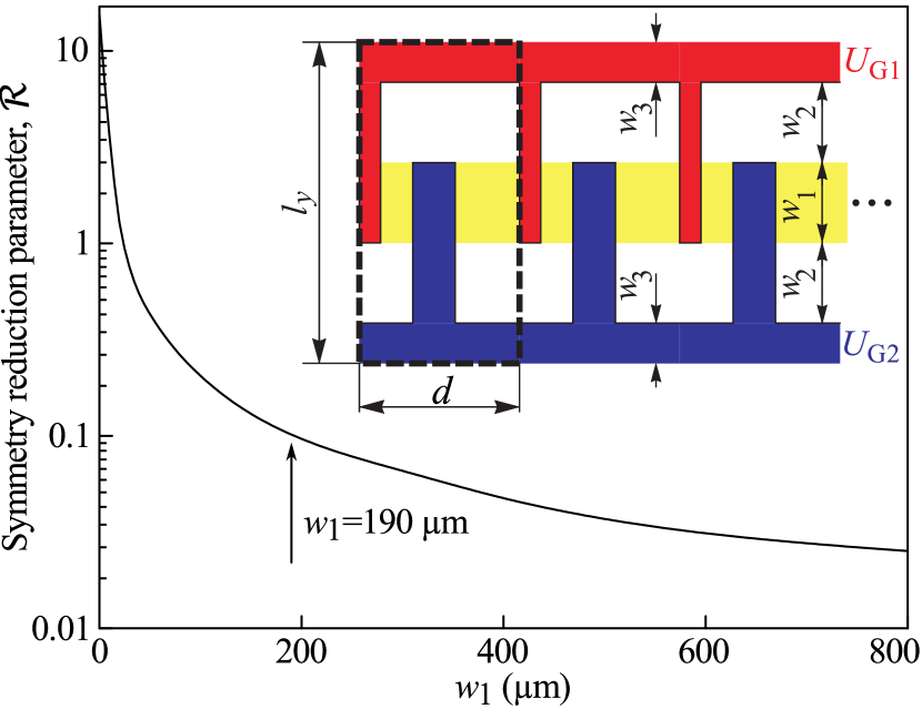
Appendix B SYMMETRY REDUCTION OF THE MODEL STRUCTURE
Due to the finite length of the stripes, the designed dual grating structure has no mirror reflection plane and, strictly speaking, its symmetry C1 imposes no restrictions on the polarization dependence of the photocurrent, even at zero magnetic field. In this case the polarization dependencies of the ratchet effects are given by Eqs. (1) and (II.4). This behavior has been reported previously for ratchet effect in similarly designed DGG structures fabricated on top of InAlAs/InGaAs/InAlAs/InP high electron mobility transistors (HEMT) Otsuji_Ganichev and graphene ratchet_graphene . Note that more details on the symmetry analysis of photocurrents in quantum wells of C1 symmetry can be found in Refs. Belkov2008 ; Wittmann .
To estimate the effect of symmetry reduction from Cs to C1 in the DGG structures studied here we consider a model structure shown in the inset in Fig. 11, the supercell is indicated by a dashed rectangle, and are, respectively, the widths of the ratchet region and the regions where only wide or narrow stripes are present. For calculation, we take the structure period m, the widths m, and assume the voltages of opposite signs to be applied to the gates and , the width of both the gates is m. The supercell parameters are taken for the sample #A metal stripes widths m and m, first and second spacing between the stripes are m and m, respectively.
By analogy with the lateral asymmetry parameter , see Eq. (2), defined for the stripes of infinite length, we can introduce two parameters
| (23) |
where is the in-plane radius-vector, is size of the supercell along the direction, and the overline still denotes the average over . The parameters and describe the systems’s asymmetry along the and directions, respectively. In the limit with being fixed, the parameter tends to and the parameter vanishes. Evidently, the degree of symmetry reduction from Cs to C1 can be estimated by the ratio .
In order to calculate the distribution of electric near field in the QW plane we follow Refs. Popov2010 ; Ivchenko_Petrov_FTT and apply the approximate method of surface currents. We generalize this method by considering the transmitted and reflected electromagnetic waves as functions of not one but two in-plane coordinates and . In this approach, the height of the stripes is considered small enough to treat them as infinitely thin and use the following boundary conditions for the radiation magnetic field above and below the grating
| (24) | ||||
Here the density of ac two-dimensional current is given by , where, at the metallic stripes, is the bulk conductivity of metal (gold) and, outside the stripes, .
For the calculations of the electrostatic potential we use a reasonable approximation of two-dimensional Laplace’s equation with the boundary conditions: at the edge of wide gate stripes (shown in blue in the inset in Fig. 11) and at the edge of narrow stripes (red).
The functions and are found numerically. As one could expect, the main contribution to the parameter comes from the yellow area in the inset in Fig. 11 while only the regions lying close to the end of the stripes contribute to .
With the increasing , the parameter goes to zero.
The calculation shows that the parameter does not exceed 0.1 and the point-group symmetry of the model structure shown in the inset in Fig. 11 is likely to be rather than and using this symmetry for the theory presented in Sec. IV is validated.
Figure 11 shows the dependence of the symmetry reduction parameter
on the width for fixed m, m.
With the increasing the parameter rapidly goes to zero.
For the experimentally studied structure m, . This demonstrates that the point-group symmetry of the
model structure of the inset in Fig. 11 is likely to be rather than
. This validates using this symmetry for the theory developed in
Sec. IV.
References
- (1) F. Jülicher, A. Ajdari, and J. Prost, Rev. Mod. Phys. 69, 1269 (1997).
- (2) P. Reimann,Phys. Rep. 361, 57 (2002).
- (3) P. Hänggi and F. Marchesoni, Rev. Mod. Phys. 81, 387 (2009).
- (4) S. Denisov, S. Flach, and P. Hänggi, Phys. Rep. 538, 77 (2014).
- (5) M. Büttiker, Z. Phys. B 68, 161 (1987).
- (6) Ya. M. Blanter and M. Büttiker, Phys. Rev. Lett. 81, 4040 (1998).
- (7) P. Reimann, M. Grifoni, and P. Hänggi, Phys. Rev. Lett. 79, 10 (1997).
- (8) A. Lorke et al., Physica B 249, 312 (1998).
- (9) A. M. Song et al., Appl. Phys. Lett. 79, 1357 (2001).
- (10) A. D. Chepelianskii, M. V. Entin, L. I. Magarill, and D. L. Shepelyansky, Eur. Phys. J. 56, 323 (2007).
- (11) A. D. Chepelianskii, M. V. Entin, L. I. Magarill, and D. L. Chepelyansky, Physica E (Amsterdam) 40, 1264 (2008).
- (12) S. Sassine, Yu. Krupko, J.-C. Portal, Z. D. Kvon, R. Murali, K. P. Martin, G. Hill, and A. D. Wieck, Phys. Rev. B 78, 045431 (2008).
- (13) P. Olbrich, E. L. Ivchenko, R. Ravash, T. Feil, S. Danilov, J. Allerdings, D. Weiss, D. Schuh, W. Wegscheider, and S. D. Ganichev, Phys. Rev. Lett. 103, 090603 (2009).
- (14) D.V. Fateev, V.V. Popov, and M.S. Shur, Semiconductors 44, 1406 (2010).
- (15) P. Olbrich, J. Karch, E. L. Ivchenko, J. Kamann, B. März, M. Fehrenbacher, D. Weiss, and S. D. Ganichev, Phys. Rev. B 83, 165320 (2011).
- (16) E. L. Ivchenko and S. D. Ganichev, Pisma v ZhETF 93, 752 (2011) [JETP Lett. 93, 673 (2011)].
- (17) E. S. Kannan, I. Bisotto, J.-C. Portal, T. J. Beck, and L. Jalabert, Appl. Phys. Lett. 101, 143504 (2012).
- (18) A. V. Nalitov, L. E. Golub, and E. L. Ivchenko, Phys. Rev. B 86, 115301 (2012).
- (19) V. V. Popov, Appl. Phys. Lett. 102, 253504 (2013).
- (20) I. V. Rozhansky, V. Yu. Kachorovskii, and M. S. Shur, Phys. Rev. Lett. 114, 246601 (2015).
- (21) V. V. Popov, D. V. Fateev, E. L. Ivchenko, and S. D. Ganichev, Phys. Rev. B 91, 235436 (2015).
- (22) P. Olbrich, J. Kamann, M. König, J. Munzert, L. Tutsch, J. Eroms, D. Weiss, M.-H. Liu, L. E. Golub, E. L. Ivchenko, V. V. Popov, D. V. Fateev, K. V. Mashinsky, F. Fromm, Th. Seyller, and S. D. Ganichev, Phys. Rev. B 93, 075422 (2016).
- (23) P. Faltermeier, G.V. Budkin, J. Unverzagt, S. Hubmann, A. Pfaller, V.V. Bel’kov, L.E. Golub, E.L. Ivchenko, Z. Adamus, G. Karczewski, T. Wojtowicz, V.V. Popov, D.V. Fateev, D.A. Kozlov, D. Weiss, and S.D. Ganichev, Phys. Rev. B 95, 155442 (2017).
- (24) V. V. Popov, D. V. Fateev, T. Otsuji, Y. M. Meziani, D. Coquillat, and W. Knap, Appl. Phys. Lett. 99, 243504 (2011).
- (25) T. Watanabe, S. A. Boubanga-Tombet, Y. Tanimoto, D. Fateev, V. Popov, D. Coquillat, W. Knap, Y. M. Meziani, Yuye Wang, H. Minamide, H. Ito, and T. Otsuji, IEEE Sensors J. 3, 89 (2013).
- (26) Y. Kurita, G. Ducournau, D. Coquillat, A. Satou, K. Kobayashi, S. Boubanga Tombet, Y. M. Meziani, V. V. Popov, W. Knap, T. Suemitsu, and T. Otsuji, Appl. Phys. Lett. 104, 251114 (2014).
- (27) S. A. Boubanga-Tombet, Y. Tanimoto, A. Satou, T. Suemitsu, Y. Wang, H. Minamide, H. Ito, D. V. Fateev, V. V. Popov, and T. Otsuji, Appl. Phys. Lett. 104, 262104 (2014).
- (28) S. N. Danilov, B. Wittmann, P. Olbrich, W. Eder, W. Prettl, L. E. Golub, E.V. Beregulin, Z. D. Kvon, N. N. Mikhailov, S. A. Dvoretsky, V. A. Shalygin, N. Q. Vinh, A. F. G. van der Meer, B. Murdin, and S. D. Ganichev, J. Appl. Phys. 105, 013106 (2009).
- (29) S. Dvoretsky, N. Mikhailov, Y. Sidorov, V. Shvets, S. Danilov, B. Wittman, and S. Ganichev, J. Electron. Mat. 39, 918 (2010).
- (30) C. Drexler, N. Dyakonova, P. Olbrich, J. Karch, M. Schafberger, K. Karpierz, Yu. Mityagin, M. B. Lifshits, F. Teppe, O. Klimenko, Y. M. Meziani, W. Knap, and S. D. Ganichev, J. Appl. Phys. 111, 124504 (2012).
- (31) P. Faltermeier, P. Olbrich, W. Probst, L. Schell, T. Watanabe, S. A. Boubanga-Tombet, T. Otsuji, and S. D. Ganichev, J. Appl. Phys. 118, 084301 (2015).
- (32) G. V. Budkin, L. E. Golub, E. L. Ivchenko, and S. D. Ganichev, JETP Lett. 104, 649 (2016).
- (33) G.V. Budkin and L.E. Golub, Phys. Rev. B 90, 125316 (2014).
- (34) S. A. Crooker, D. A. Tulchinsky, J. Levy, D. D. Awschalom, R. Garcia, and N. Samarth, Phys. Rev. Lett. 75, 505 (1995).
- (35) J. C. Egues and J. W. Wilkins, Phys. Rev. 58, R16012 (1998).
- (36) J. Jaroszynski, T. Andrearczyk, G. Karczewski, J. Wróbel, T. Wojtowicz, E. Papis, E. Kaminska, A. Piotrowska, D. Popovic, and T. Dietl, Phys. Rev. Lett. 89, 266802 (2002).
- (37) S. D. Ganichev, S. A. Tarasenko, V. V. Bel’kov, P. Olbrich, W. Eder, D. R. Yakovlev, V. Kolkovsky, W. Zaleszczyk, G. Karczewski, T. Wojtowicz, and D. Weiss, Phys. Rev. Lett. 102, 156602 (2009).
- (38) M. K. Kneip, D. R. Yakovlev, M. Bayer, G. Karczewski, T. Wojtowicz, and J. Kossut, Appl. Phys. Lett. 88, 152105 (2006).
- (39) J. A. Gaj, R. Planel, and G. Fishman, Solid State Commun. 29, 435 (1979).
- (40) J. K. Furdyna, J. Appl. Phys. 64, R29 (1988).
- (41) M. Staab, M. Matuschek, P. Pereyra, M. Utz, D. Schuh, D. Bougeard, R. R. Gerhardts, and D. Weiss, New J. Phys. 17, 043035 (2015).
- (42) S.D. Ganichev, W. Prettl, P.G. Huggard, Phys. Rev. Lett. 71, 3882 (1993).
- (43) Z. D. Kvon, S. N. Danilov, N. N. Mikhailov, S. A. Dvoretsky, and S. D. Ganichev, Physica E 40, 1885 (2008).
- (44) M. Kohda, V. Lechner, Y. Kunihashi, T. Dollinger, P. Olbrich, C. Schönhuber, I. Caspers, V.V. Bel’kov, L.E. Golub, D. Weiss, K. Richter, J. Nittaand S.D. Ganichev Phys. Rev. B Rapid Communic. 86, 081306 (2012).
- (45) S.D. Ganichev, Physica B 273-274, 737 (1999).
- (46) P. Schneider, J. Kainz, S.D. Ganichev, V.V. Bel’kov, S.N. Danilov, M.M. Glazov, L.E. Golub, U. Rössler, W. Wegscheider, D. Weiss, D. Schuh, and W. Prettl, J. Appl. Phys. 96, 420 (2004).
- (47) S. D. Ganichev, W. Prettl, Intense Terahertz Excitation of Semiconductors (Oxford University Press, Oxford, 2006).
- (48) B.E.A. Saleh and M.C. Teich, Fundamentals of Photonics (John Wiley & Sons, Inc., 2007).
- (49) V. V. Bel’kov, S. D. Ganichev, E. L. Ivchenko, S. A. Tarasenko, W. Weber, S. Giglberger, M. Olteanu, H.-P. Tranitz, S. N. Danilov, Petra Schneider, W. Wegscheider, D. Weiss, and W. Prettl, J. Phys.: Condens. Matter 17, 3405 (2005).
- (50) J. Karch, C. Drexler, P. Olbrich, M. Fehrenbacher, M. Hirmer, M. M. Glazov, S. A. Tarasenko, E. L. Ivchenko, B. Birkner, J. Eroms, D. Weiss, R. Yakimova, S. Lara-Avila, S. Kubatkin, M. Ostler, T. Seyller, and S. D. Ganichev, Phys. Rev. Lett. 107, 276601 (2011).
- (51) M. M. Glazov and S. D. Ganichev, Phys. Rep. 535, 101 (2014).
- (52) The same assumption has been made to derive Eq. (6) for ratchet effects at zero magnetic field, see Eqs. (12) and (22) in Ref. Review_JETP_Lett .
- (53) O. E. Raichev, Phys. Rev. B 78, 125304 (2008).
- (54) E. L. Ivchenko and M. I. Petrov, Phys. Solid State 56, 1833 (2014).
- (55) I. A. Dmitriev, A. D. Mirlin, D. G. Polyakov, and M. A. Zudov, Rev. Mod. Phys. 84, 1709 (2012).
- (56) I. A. Dmitriev, J. Phys. Conf. Ser. 334, 012015 (2011).
- (57) A. A. Dremin, D. R. Yakovlev, A. A. Sirenko, S. I. Gubarev, O. P. Shabelsky, A. Waag, and M. Bayer, Phys. Rev. B 72, 195337 (2005).
- (58) T. Dietl, in Handbook on Semiconductors, vol. 3b, Ed. T.S. Moss (North-Holland, Amsterdam, 1994).
- (59) Introduction to the Physics of Diluted Magnetic Semiconductors, Eds. J. Kossut and J. A. Gaj (Springer, Berlin 2010).
- (60) Introduction to the Physics of Diluted Magnetic Semiconductors, eds. J. Kossut and J.A. Gaj (Springer 2011).
- (61) V. V. Bel’kov and S. D. Ganichev, Semicond. Sci. Technol. 23, 114003 (2008).
- (62) B. Wittmann, S.N. Danilov, V.V. Bel’kov, S.A. Tarasenko, E.G. Novik, H. Buhmann, C. Brüne, L.W. Molenkamp, E.L. Ivchenko, Z.D. Kvon, N.N. Mikhailov, S.A. Dvoretsky, N. Q. Vinh, A. F. G. van der Meer, B. Murdin, and S.D. Ganichev Semicond. Sci. and Technol. 25, 095005 (2010).