Hybrid Precoder and Combiner Design with Low Resolution Phase Shifters in mmWave MIMO Systems

Zihuan Wang,  Ming Li,  Qian Liu,  and A. Lee Swindlehurst Zihuan Wang and Ming Li are with the School of Information and Communication Engineering, Dalian University of Technology, Dalian, Liaoning 116024, China, (e-mail: wangzihuan@mail.dlut.edu.cn, mli@dlut.edu.cn).Qian Liu is with the School of Computer Science and Technology, Dalian University of Technology, Dalian, Liaoning 116024, China (e-mail: qianliu@dlut.edu.cn).A. L. Swindlehurst is with the Center for Pervasive Communications and Computing, University of California, Irvine, CA 92697 USA and also with the Institute for Advanced Study, Technical University of Munich,Munchen 80333, Germany (e-mail: swindle@uci.edu).This paper is supported by the National Natural Science Foundation of China (Grant No. 61671101 and 61601080) and the Fundamental Research Funds for the Central Universities (Grant No. DUT15RC(3)121 and DUT17JC10).
Abstract

Millimeter wave (mmWave) communications have been considered as a key technology for next generation cellular systems and Wi-Fi networks because of its advances in providing orders-of-magnitude wider bandwidth than current wireless networks. Economical and energy-efficient analog/digial hybrid precoding and combining transceivers have been often proposed for mmWave massive multiple-input multiple-output (MIMO) systems to overcome the severe propagation loss of mmWave channels. One major shortcoming of existing solutions lies in the assumption of infinite or high-resolution phase shifters (PSs) to realize the analog beamformers. However, low-resolution PSs are typically adopted in practice to reduce the hardware cost and power consumption. Motivated by this fact, in this paper, we investigate the practical design of hybrid precoders and combiners with low-resolution PSs in mmWave MIMO systems. In particular, we propose an iterative algorithm which successively designs the low-resolution analog precoder and combiner pair for each data stream, aiming at conditionally maximizing the spectral efficiency. Then, the digital precoder and combiner are computed based on the obtained effective baseband channel to further enhance the spectral efficiency. In an effort to achieve an even more hardware-efficient large antenna array, we also investigate the design of hybrid beamformers with one-bit resolution (binary) PSs, and present a novel binary analog precoder and combiner optimization algorithm with quadratic complexity in the number of antennas. The proposed low-resolution hybrid beamforming design is further extended to multiuser MIMO communication systems. Simulation results demonstrate the performance advantages of the proposed algorithms compared to existing low-resolution hybrid beamforming designs, particularly for the one-bit resolution PS scenario.

Index Terms:
Millimeter wave (mmWave) communications, hybrid precoder, multiple-input multiple-output (MIMO), phase shifters, one-bit quantization.

I Introduction

The past decade has witnessed the exponential growth of data traffic along with the rapid proliferation of wireless devices. This flood of mobile traffic has significantly exacerbated spectrum congestion in current frequency bands, and therefore stimulated intensive interest in exploiting new spectrum bands for wireless communications. Millimeter wave (mmWave) wireless communications, operating in the frequency bands from 30-300 GHz, have been demonstrated as a promising candidate to fundamentally solve the spectrum congestion problem [1]-[3].

However, challenges always come along with opportunities. MmWave communications still need to overcome several technical difficulties before real-world deployment. As a negative result of the ten-fold increase of the carrier frequency, the propagation loss in mmWave bands is much higher than that of conventional frequency bands (e.g. 2.4 GHz) due to atmospheric absorption, rain attenuation, and low penetration [4]. From a positive perspective, the smaller wavelength of mmWave signals allows a large antenna array to be packed in a small physical dimension [5]. With the aid of pre/post-coding techniques in massive multiple-input multiple-output (MIMO) systems, the large antenna array can provide sufficient beamforming gain to overcome the severe propagation loss of mmWave channels. It also enables simultaneous transmission of multiple data streams resulting in significant improvements to spectral efficiency.

For MIMO systems operating in conventional cellular frequency bands, the full-digital precoder and combiner are completely realized in the digital domain by adjusting both the magnitude and phase of the baseband signals. However, these conventional full-digital schemes require a large number of expensive and energy-intensive radio frequency (RF) chains, analog-to-digital converters (ADCs), and digital-to-analog converters (DACs). Since mmWave communication systems operate at much higher carrier frequencies and wider bandwidths, the enormous cost and power consumption of the required RF chains and ADCs/DACs make the adoption of full-digital precoding and combining schemes impractical for mmWave systems. Recently, economical and energy-efficient analog/digital hybrid precoders and combiners have been advocated as a promising approach to tackle this issue. The hybrid precoding approaches adopt a large number of phase shifters (PSs) to implement high-dimensional analog precoders to compensate for the severe path-loss at mmWave bands, and a small number of RF chains and DACs to realize low-dimensional digital precoders to provide the necessary flexibility to perform advanced multiplexing/multiuser techniques.

The investigation of hybrid precoder and combiner design has attracted extensive attention in recent years because of its potential energy efficiency for mmWave MIMO communications. The major challenges in designing hybrid precoders are the practical constraints associated with the analog components, such as the requirement that the analog precoding be implemented with constant modulus PSs. Thus, hybrid precoder design typically requires the solution of various matrix factorization problems with constant modulus constraints. In particular, a popular solution to maximize the spectral efficiency of point-to-point transmission is to minimize the Euclidean distance between the hybrid precoder and the full-digital precoder [6]-[10]. Hybrid precoder design for partially-connected architectures are also studied in [11]-[13]. Due to the special characteristics of mmWave channels, codebook-based hybrid precoder designs are commonly proposed [14]-[18], in which the columns of the analog precoder are selected from certain candidate vectors, such as array response vectors of the channel and discrete Fourier transform (DFT) beamformers. Extensions of the hybrid beamformer design to multiuser mmWave MIMO systems have also been investigated in [19]-[27].

The aforementioned existing hybrid precoder and combiner designs generally assume that infinite or high-resolution PSs are used for implementing the analog beamformers in order to achieve satisfactory performance close to the full-digital scheme. However, implementing infinite/high-resolution PSs at mmWave frequencies would significantly increase the energy consumption and complexity of the required hardware circuits [28], [29]. Obviously, it is impractical to employ infinite/high-resolution PSs for mmWave systems and real-world analog beamformers will be implemented with low-resolution PSs. Consequently, an important research direction is the exploration of signal processing techniques for hybrid analog/digital architectures that can mitigate the loss of beamforming accuracy due to the low-resolution PSs.

A straightforward approach to obtain the finite-resolution beamformer is to design the infinite-resolution analog beamformer first, and then directly quantize each phase term to a finite set [30]. However, this solution becomes inefficient when the PSs have very low resolution. An alternative solution for hybrid beamforming with finite-resolution PSs is codebook-based design [14]-[18]. However, for low-resolution PSs, the size of the codebook is very small and the resulting performance is not satisfactory. In [31], [32], Sohrabi and Yu proposed to iteratively design the low-resolution hybrid precoder to maximize the spectral efficiency. However, the performance of this algorithm often suffers when one-bit quantized PSs are applied.

In this paper, we first consider the problem of designing hybrid precoders and combiners with low-resolution PSs for a point-to-point mmWave MIMO system. The objective of the proposed algorithm is to minimize the performance loss caused by the low-resolution PSs while maintaining a low computational complexity. To achieve this goal, we propose to successively design the low-resolution analog precoder and combiner pair for each data stream, aiming at conditionally maximizing the spectral efficiency. An iterative phase matching algorithm is introduced to implement the low-resolution analog precoder and combiner pair. Then, the digital precoder and combiner are computed based on the obtained effective baseband channel to further enhance the spectral efficiency.

Note that the power consumption and cost of the PS are proportional to its resolution. For example, a 4-bit (i.e. 22.5superscript22.522.5^{\circ}) resolution PS at mmWave frequencies requires 45-106 mW, while a 3-bit (i.e. 45superscript4545^{\circ}) resolution PS needs only 15 mW [29]. In an effort to achieve maximum hardware efficiency, we also investigate the design of hybrid beamformers with one-bit resolution (binary) PSs. Inspired by the findings in [33], we present a binary analog precoder and combiner optimization algorithm under a rank-1 approximation of the interference-included equivalent channel. This algorithm has quadratic complexity in the number of antennas and can achieve almost the same performance as the optimal exhaustive search method. Finally, our investigation of low-resolution hybrid precoders and combiners is extended to multiuser mmWave MIMO systems. Numerical results in the simulation section demonstrate that the proposed algorithms can offer a performance improvement compared with existing low-resolution hybrid beamforming schemes, especially for the one-bit resolution PS scenario.

Notation: The following notation is used throughout this paper. Boldface lower-case and upper-case letters indicate column vectors and matrices, respectively. ()Tsuperscript𝑇(\cdot)^{T} and ()Hsuperscript𝐻(\cdot)^{H} denote the transpose and transpose-conjugate operations, respectively. 𝔼{}𝔼\mathbb{E}\{\cdot\} represents statistical expectation. 𝔢{}𝔢\mathfrak{Re}\{\cdot\} extracts the real part of a complex number; sign()sign\mathrm{sign}(\cdot) denotes the sign operator; angle{}angle\mathrm{angle}\{\cdot\} represents the phase of a complex number. 𝐈Lsubscript𝐈𝐿\mathbf{I}_{L} indicates an L×L𝐿𝐿L\times L identity matrix. \mathbb{C} denotes the set of complex numbers. |𝐀|𝐀|\mathbf{A}| denotes the determinant of matrix 𝐀𝐀\mathbf{A}. |𝒜|𝒜|\mathcal{A}| denotes the cardinality of set 𝒜𝒜\mathcal{A}. |a|𝑎|a| and 𝐚norm𝐚\|\mathbf{a}\| are the magnitude and norm of a scalar a𝑎a and vector 𝐚𝐚\mathbf{a}, respectively. 𝐀Fsubscriptnorm𝐀𝐹\|\mathbf{A}\|_{F} denotes the Frobenius norm of matrix 𝐀𝐀\mathbf{A}. Finally, we adopt a Matlab-like matrix indexing notation: 𝐀(:,i)𝐀:𝑖\mathbf{A}(:,i) denotes the i𝑖i-th column of matrix 𝐀𝐀\mathbf{A}; 𝐀(i,j)𝐀𝑖𝑗\mathbf{A}(i,j) denotes the element of the i𝑖i-th row and the j𝑗j-th column of matrix 𝐀𝐀\mathbf{A}; 𝐚(i)𝐚𝑖\mathbf{a}(i) denotes the i𝑖i-th element of vector 𝐚𝐚\mathbf{a}.

II System Model and Problem Formulation

II-A Point-to-Point mmWave MIMO System Model

Refer to caption
Figure 1: The point-to-point mmWave MIMO system using hybrid precoder and combiner.

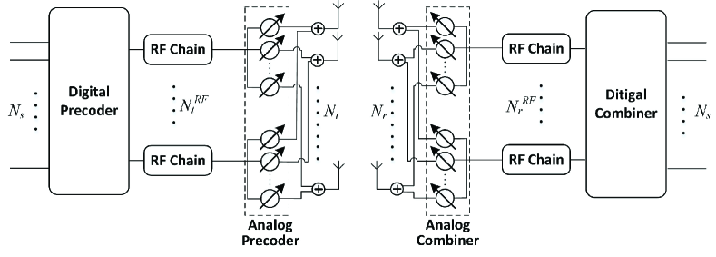
We first consider a point-to-point mmWave MIMO system using a hybrid precoder and combiner with low-resolution PSs, as illustrated in Fig. 1. The transmitter employs Ntsubscript𝑁𝑡N_{t} antennas and NtRFsubscriptsuperscript𝑁𝑅𝐹𝑡N^{RF}_{t} RF chains to simultaneously transmit Nssubscript𝑁𝑠N_{s} data streams to the receiver which is equipped with Nrsubscript𝑁𝑟N_{r} antennas and NrRFsubscriptsuperscript𝑁𝑅𝐹𝑟N^{RF}_{r} RF chains. To ensure the efficiency of the mmWave communication with a limited number of RF chains, the number of data streams and the number of RF chains are constrained as Ns=NtRF=NrRFsubscript𝑁𝑠superscriptsubscript𝑁𝑡𝑅𝐹superscriptsubscript𝑁𝑟𝑅𝐹N_{s}=N_{t}^{RF}=N_{r}^{RF}.

The transmitted symbols are first processed by a baseband digital precoder 𝐅BBNtRF×Nssubscript𝐅𝐵𝐵superscriptsuperscriptsubscript𝑁𝑡𝑅𝐹subscript𝑁𝑠\mathbf{F}_{BB}\in\mathbb{C}^{N_{t}^{RF}\times N_{s}}, then up-converted to the RF domain via NtRFsuperscriptsubscript𝑁𝑡𝑅𝐹N_{t}^{RF} RF chains before being precoded with an analog precoder 𝐅RFsubscript𝐅𝑅𝐹\mathbf{F}_{RF} of dimension Nt×NtRFsubscript𝑁𝑡superscriptsubscript𝑁𝑡𝑅𝐹N_{t}\times N_{t}^{RF}. While the baseband digital precoder 𝐅BBsubscript𝐅𝐵𝐵\mathbf{F}_{BB} enables both amplitude and phase modifications, the elements of the analog precoder 𝐅RFsubscript𝐅𝑅𝐹\mathbf{F}_{RF}, which are implemented by the PSs, have a constant amplitude 1Nt1subscript𝑁𝑡\frac{1}{\sqrt{N_{t}}} and quantized phases: 𝐅RF(i,j)=1Ntejϑi,jsubscript𝐅𝑅𝐹𝑖𝑗1subscript𝑁𝑡superscript𝑒𝑗subscriptitalic-ϑ𝑖𝑗\mathbf{F}_{RF}(i,j)=\frac{1}{\sqrt{N_{t}}}e^{j\vartheta_{i,j}}, in which the phase ϑi,jsubscriptitalic-ϑ𝑖𝑗\vartheta_{i,j} is quantized as ϑi,j{2πb2Bb=1,2,,2B}subscriptitalic-ϑ𝑖𝑗conditional-set2𝜋𝑏superscript2𝐵𝑏12superscript2𝐵\vartheta_{i,j}\in\mathcal{B}\triangleq\{\frac{2\pi b}{2^{B}}\mid b=1,2,\ldots,2^{B}\}, and B𝐵B is the number of bits to control the phase. We denote the constraint set of the analog precoder as follows: 𝐅RF(i,j){1Ntej2πb2Bb=1,2,,2B}subscript𝐅𝑅𝐹𝑖𝑗conditional-set1subscript𝑁𝑡superscript𝑒𝑗2𝜋𝑏superscript2𝐵𝑏12superscript2𝐵\mathbf{F}_{RF}(i,j)\in\mathcal{F}\triangleq\{\frac{1}{\sqrt{N_{t}}}e^{j\frac{2\pi b}{2^{B}}}\mid b=1,2,\ldots,2^{B}\}. Obviously, a larger number of bits B𝐵B leads to finer resolution for the PSs and potentially better performance, but also results in higher hardware complexity and power consumption.

The discrete-time transmitted signal can be written in the following form

𝐱=P𝐅RF𝐅BB𝐬𝐱𝑃subscript𝐅𝑅𝐹subscript𝐅𝐵𝐵𝐬\mathbf{x}=\sqrt{P}\mathbf{F}_{RF}\mathbf{F}_{BB}\mathbf{s} (1)

where 𝐬𝐬\mathbf{s} is the Ns×1subscript𝑁𝑠1N_{s}\times 1 symbol vector, 𝔼{𝐬𝐬H}=1Ns𝐈Ns𝔼superscript𝐬𝐬𝐻1subscript𝑁𝑠subscript𝐈subscript𝑁𝑠\mathbb{E}\{\mathbf{s}\mathbf{s}^{H}\}=\frac{1}{N_{s}}\mathbf{I}_{N_{s}}, P𝑃P represents transmit power and this power constraint is enforced by normalizing 𝐅BBsubscript𝐅𝐵𝐵\mathbf{F}_{BB} such that 𝐅RF𝐅BBF2=Nssubscriptsuperscriptnormsubscript𝐅𝑅𝐹subscript𝐅𝐵𝐵2𝐹subscript𝑁𝑠\|\mathbf{F}_{RF}\mathbf{F}_{BB}\|^{2}_{F}=N_{s}.

We consider a narrow-band slow-fading propagation channel, which yields the following received signal

𝐲𝐲\displaystyle\mathbf{y} =\displaystyle= 𝐇𝐱+𝐧𝐇𝐱𝐧\displaystyle\mathbf{H}\mathbf{x}+\mathbf{n} (2)
=\displaystyle= P𝐇𝐅RF𝐅BB𝐬+𝐧𝑃subscript𝐇𝐅𝑅𝐹subscript𝐅𝐵𝐵𝐬𝐧\displaystyle\sqrt{P}\mathbf{H}\mathbf{F}_{RF}\mathbf{F}_{BB}\mathbf{s}+\mathbf{n}

where 𝐲𝐲\mathbf{y} is the Nr×1subscript𝑁𝑟1N_{r}\times 1 received signal vector, 𝐇𝐇\mathbf{H} is the Nr×Ntsubscript𝑁𝑟subscript𝑁𝑡N_{r}\times N_{t} channel matrix, and 𝐧𝒞𝒩(𝟎,σ2𝐈Nr)𝐧𝒞𝒩0superscript𝜎2subscript𝐈subscript𝑁𝑟\mathbf{n}\thicksim\mathcal{CN}(\mathbf{0},\sigma^{2}\mathbf{I}_{N_{r}}) is the complex Gaussian noise vector corrupting the received signal.

The receiver employs an analog combiner implemented by the PSs and a digital combiner using NrRFsuperscriptsubscript𝑁𝑟𝑅𝐹N_{r}^{RF} RF chains to process the received signal. The signal after the spatial processing has the form

𝐬^=P𝐖BBH𝐖RFH𝐇𝐅RF𝐅BB𝐬+𝐖BBH𝐖RFH𝐧^𝐬𝑃subscriptsuperscript𝐖𝐻𝐵𝐵subscriptsuperscript𝐖𝐻𝑅𝐹subscript𝐇𝐅𝑅𝐹subscript𝐅𝐵𝐵𝐬subscriptsuperscript𝐖𝐻𝐵𝐵subscriptsuperscript𝐖𝐻𝑅𝐹𝐧\mathbf{\widehat{s}}=\sqrt{P}\mathbf{W}^{H}_{BB}\mathbf{W}^{H}_{RF}\mathbf{H}\mathbf{F}_{RF}\mathbf{F}_{BB}\mathbf{s}+\mathbf{W}^{H}_{BB}\mathbf{W}^{H}_{RF}\mathbf{n} (3)

where 𝐖RFsubscript𝐖𝑅𝐹\mathbf{W}_{RF} is the Nr×NrRFsubscript𝑁𝑟superscriptsubscript𝑁𝑟𝑅𝐹N_{r}\times N_{r}^{RF} analog combiner whose elements have the same constraint as 𝐅RFsubscript𝐅𝑅𝐹\mathbf{F}_{RF}, i.e. 𝐖RF(i,j)=1Nrejφi,jsubscript𝐖𝑅𝐹𝑖𝑗1subscript𝑁𝑟superscript𝑒𝑗subscript𝜑𝑖𝑗\mathbf{W}_{RF}(i,j)=\frac{1}{\sqrt{N_{r}}}e^{j\varphi_{i,j}}, φi,jsubscript𝜑𝑖𝑗\varphi_{i,j}\in\mathcal{B} and thus 𝐖RF(i,j)𝒲{1Nrej2πb2Bb=1,2,,2B}subscript𝐖𝑅𝐹𝑖𝑗𝒲conditional-set1subscript𝑁𝑟superscript𝑒𝑗2𝜋𝑏superscript2𝐵𝑏12superscript2𝐵\mathbf{W}_{RF}(i,j)\in\mathcal{W}\triangleq\{\frac{1}{\sqrt{N_{r}}}e^{j\frac{2\pi b}{2^{B}}}\mid b=1,2,\ldots,2^{B}\}, 𝐖BBsubscript𝐖𝐵𝐵\mathbf{W}_{BB} is the NrRF×Nssuperscriptsubscript𝑁𝑟𝑅𝐹subscript𝑁𝑠N_{r}^{RF}\times N_{s} digital baseband combiner and the combiner matrices are normalized such that 𝐖RF𝐖BBF2=Nssubscriptsuperscriptnormsubscript𝐖𝑅𝐹subscript𝐖𝐵𝐵2𝐹subscript𝑁𝑠\|\mathbf{W}_{RF}\mathbf{W}_{BB}\|^{2}_{F}=N_{s}.

II-B Problem Formulation

We consider the practical and hardware-efficient scenario in which the PSs have very low-resolution (e.g. B=1,2𝐵12B=1,2) to reduce the power consumption and complexity. Under this hardware constraint, we aim to jointly design the hybrid precoder and combiner for a mmWave MIMO system. When Gaussian symbols are transmitted over the mmWave MIMO channel, the achievable spectral efficiency is given by

R𝑅\displaystyle R =\displaystyle= log2(|𝐈Ns+PNs𝐑n1𝐖BBH𝐖RFH𝐇𝐅RF𝐅BB×\displaystyle\mathrm{log}_{2}\Bigg{(}\bigg{|}\mathbf{I}_{N_{s}}+\frac{P}{N_{s}}\mathbf{R}_{n}^{-1}\mathbf{W}^{H}_{BB}\mathbf{W}^{H}_{RF}\mathbf{H}\mathbf{F}_{RF}\mathbf{F}_{BB}\times (4)
𝐅BBH𝐅RFH𝐇H𝐖RF𝐖BB|),\displaystyle\hskip 62.59596pt\mathbf{F}_{BB}^{H}\mathbf{F}_{RF}^{H}\mathbf{H}^{H}\mathbf{W}_{RF}\mathbf{W}_{BB}\bigg{|}\Bigg{)},

where 𝐑nσn2𝐖BBH𝐖RFH𝐖RF𝐖BBsubscript𝐑𝑛superscriptsubscript𝜎𝑛2subscriptsuperscript𝐖𝐻𝐵𝐵subscriptsuperscript𝐖𝐻𝑅𝐹subscript𝐖𝑅𝐹subscript𝐖𝐵𝐵\mathbf{R}_{n}\triangleq\sigma_{n}^{2}\mathbf{W}^{H}_{BB}\mathbf{W}^{H}_{RF}\mathbf{W}_{RF}\mathbf{W}_{BB} is the noise covariance matrix after combining. We aim to jointly design the digital beamformers 𝐅BBsubscript𝐅𝐵𝐵\mathbf{F}_{BB}, 𝐖BBsubscript𝐖𝐵𝐵\mathbf{W}_{BB} as well as the low-resolution analog beamformers 𝐅RFsubscript𝐅𝑅𝐹\mathbf{F}_{RF}, 𝐖RFsubscript𝐖𝑅𝐹\mathbf{W}_{RF} to maximize the spectral efficiency:

{𝐅RF,𝐅BB,𝐖RF,𝐖BB}=argmaxRsuperscriptsubscript𝐅𝑅𝐹superscriptsubscript𝐅𝐵𝐵superscriptsubscript𝐖𝑅𝐹superscriptsubscript𝐖𝐵𝐵argmax𝑅\displaystyle\Big{\{}\mathbf{F}_{RF}^{\star},\mathbf{F}_{BB}^{\star},\mathbf{W}_{RF}^{\star},\mathbf{W}_{BB}^{\star}\Big{\}}=\textrm{arg}~{}\textrm{max}~{}R (5)
s. t.𝐅RF(i,j),i,j,formulae-sequences. t.subscript𝐅𝑅𝐹𝑖𝑗for-all𝑖𝑗\displaystyle\textrm{s. t.}~{}~{}~{}~{}\mathbf{F}_{RF}(i,j)\in\mathcal{F},\forall i,j,
𝐖RF(i,j)𝒲,i,j,subscript𝐖𝑅𝐹𝑖𝑗𝒲for-all𝑖𝑗\displaystyle\mathbf{W}_{RF}(i,j)\in\mathcal{W},\forall i,j,
𝐅RF𝐅BBF2=Ns,subscriptsuperscriptnormsubscript𝐅𝑅𝐹subscript𝐅𝐵𝐵2𝐹subscript𝑁𝑠\displaystyle\|\mathbf{F}_{RF}\mathbf{F}_{BB}\|^{2}_{F}=N_{s},
𝐖RF𝐖BBF2=Ns.subscriptsuperscriptnormsubscript𝐖𝑅𝐹subscript𝐖𝐵𝐵2𝐹subscript𝑁𝑠\displaystyle\|\mathbf{W}_{RF}\mathbf{W}_{BB}\|^{2}_{F}=N_{s}.

Obviously, the optimization problem (5) is a non-convex NP-hard problem. In the next section, we attempt to decompose the original problem into a series of sub-problems and seek a sub-optimal solution with low-complexity and satisfactory performance.

III Low-Resolution Hybrid Precoder and Combiner Design

To simplify the joint hybrid precoder and combiner design, the objective problem is decomposed into two separate optimizations. We first focus on the joint design of the analog precoder 𝐅RFsubscript𝐅𝑅𝐹\mathbf{F}_{RF} and combiner 𝐖RFsubscript𝐖𝑅𝐹\mathbf{W}_{RF}. Then, having the effective baseband channel associated with the obtained optimal analog precoder and combiner, the digital precoder 𝐅BBsubscript𝐅𝐵𝐵\mathbf{F}_{BB} and combiner 𝐖BBsubscript𝐖𝐵𝐵\mathbf{W}_{BB} are computed to further maximize the spectral efficiency.

III-A Low-Resolution Analog Precoder and Combiner Design

We observe that under the assumption of high signal-to-noise-ratio (SNR), the achievable spectral efficiency in (4) can be approximated as

R𝑅\displaystyle R \displaystyle\approx log2(|PNs𝐑n1𝐖BBH𝐖RFH𝐇𝐅RF𝐅BB×\displaystyle\mathrm{log}_{2}\Bigg{(}\bigg{|}\frac{P}{N_{s}}\mathbf{R}_{n}^{-1}\mathbf{W}^{H}_{BB}\mathbf{W}^{H}_{RF}\mathbf{H}\mathbf{F}_{RF}\mathbf{F}_{BB}\times (6)
𝐅BBH𝐅RFH𝐇H𝐖RF𝐖BB|).\displaystyle\hskip 45.52458pt\mathbf{F}_{BB}^{H}\mathbf{F}_{RF}^{H}\mathbf{H}^{H}\mathbf{W}_{RF}\mathbf{W}_{BB}\bigg{|}\Bigg{)}.

While the per-antenna SNR in mmWave systems is typically low, the post-combining SNR should be high enough to justify this approximation. In addition, it has been verified in [32] that for large-scale MIMO systems, the optimal analog beamformers are approximately orthogonal, i.e. 𝐅RFH𝐅RF𝐈NtRFproportional-tosuperscriptsubscript𝐅𝑅𝐹𝐻subscript𝐅𝑅𝐹subscript𝐈subscriptsuperscript𝑁𝑅𝐹𝑡\mathbf{F}_{RF}^{H}\mathbf{F}_{RF}\propto\mathbf{I}_{N^{RF}_{t}}. This enables us to assume 𝐅BB𝐅BBHζ2𝐈Nssubscript𝐅𝐵𝐵superscriptsubscript𝐅𝐵𝐵𝐻superscript𝜁2subscript𝐈subscript𝑁𝑠\mathbf{F}_{BB}\mathbf{F}_{BB}^{H}\approx\zeta^{2}\mathbf{I}_{N_{s}} when NtRF=Nssubscriptsuperscript𝑁𝑅𝐹𝑡subscript𝑁𝑠N^{RF}_{t}=N_{s}, where ζ2superscript𝜁2\zeta^{2} is a normalization factor. Similarly, we have 𝐖BB𝐖BBHξ2𝐈Nssubscript𝐖𝐵𝐵superscriptsubscript𝐖𝐵𝐵𝐻superscript𝜉2subscript𝐈subscript𝑁𝑠\mathbf{W}_{BB}\mathbf{W}_{BB}^{H}\approx\xi^{2}\mathbf{I}_{N_{s}} and 𝐖BBH𝐖RFH𝐖RF𝐖BB𝐈Nssuperscriptsubscript𝐖𝐵𝐵𝐻superscriptsubscript𝐖𝑅𝐹𝐻subscript𝐖𝑅𝐹subscript𝐖𝐵𝐵subscript𝐈subscript𝑁𝑠\mathbf{W}_{BB}^{H}\mathbf{W}_{RF}^{H}\mathbf{W}_{RF}\mathbf{W}_{BB}\approx\mathbf{I}_{N_{s}}. Let γ2ζ2ξ2superscript𝛾2superscript𝜁2superscript𝜉2\gamma^{2}\triangleq\zeta^{2}\xi^{2}, then (6) can be further simplified as

Rlog2(|Pγ2Nsσ2𝐖RFH𝐇𝐅RF𝐅RFH𝐇H𝐖RF|)𝑅subscriptlog2𝑃superscript𝛾2subscript𝑁𝑠superscript𝜎2subscriptsuperscript𝐖𝐻𝑅𝐹subscript𝐇𝐅𝑅𝐹superscriptsubscript𝐅𝑅𝐹𝐻superscript𝐇𝐻subscript𝐖𝑅𝐹\displaystyle R\approx\mathrm{log}_{2}\Bigg{(}\bigg{|}\frac{P\gamma^{2}}{N_{s}\sigma^{2}}\mathbf{W}^{H}_{RF}\mathbf{H}\mathbf{F}_{RF}\mathbf{F}_{RF}^{H}\mathbf{H}^{H}\mathbf{W}_{RF}\bigg{|}\Bigg{)} (7)
=(a)Nslog2(Pγ2Nsσ2)+2×log2(|𝐖RFH𝐇𝐅RF|)𝑎subscript𝑁𝑠subscriptlog2𝑃superscript𝛾2subscript𝑁𝑠superscript𝜎22subscriptlog2subscriptsuperscript𝐖𝐻𝑅𝐹subscript𝐇𝐅𝑅𝐹\displaystyle\overset{(a)}{=}N_{s}\mathrm{log}_{2}\left(\frac{P\gamma^{2}}{N_{s}\sigma^{2}}\right)+2\times\mathrm{log}_{2}\Bigg{(}\bigg{|}\mathbf{W}^{H}_{RF}\mathbf{H}\mathbf{F}_{RF}\bigg{|}\Bigg{)} (8)

where (a)𝑎(a) follows since |𝐗𝐘|=|𝐗||𝐘|𝐗𝐘𝐗𝐘|\mathbf{X}\mathbf{Y}|=|\mathbf{X}||\mathbf{Y}| when 𝐗𝐗\mathbf{X} and 𝐘𝐘\mathbf{Y} are both square matrices. Therefore, the analog precoder and combiner design with low-resolution PSs can be approximately reformulated as:

{𝐅RF,𝐖RF}=superscriptsubscript𝐅𝑅𝐹superscriptsubscript𝐖𝑅𝐹absent\displaystyle\left\{\mathbf{F}_{RF}^{\star},\mathbf{W}_{RF}^{\star}\right\}= argmaxlog2(|𝐖RFH𝐇𝐅RF|)argmaxsubscriptlog2subscriptsuperscript𝐖𝐻𝑅𝐹subscript𝐇𝐅𝑅𝐹\displaystyle\;\textrm{arg}\;{\textrm{max}}\;\mathrm{log}_{2}\bigg{(}\Big{|}\mathbf{W}^{H}_{RF}\mathbf{H}\mathbf{F}_{RF}\Big{|}\bigg{)} (9)
s.t.formulae-sequencest\displaystyle\mathrm{s.\,t.} 𝐅RF(i,j),i,j,subscript𝐅𝑅𝐹𝑖𝑗for-all𝑖𝑗\displaystyle\mathbf{F}_{RF}(i,j)\in\mathcal{F},\forall i,j,
𝐖RF(i,j)𝒲,i,j.subscript𝐖𝑅𝐹𝑖𝑗𝒲for-all𝑖𝑗\displaystyle\mathbf{W}_{RF}(i,j)\in\mathcal{W},\forall i,j.

Unfortunately, the optimization problem (9) is still NP-hard and has exponential complexity 𝒪(||NtNtRF|𝒲|NrNrRF)𝒪superscriptsubscript𝑁𝑡superscriptsubscript𝑁𝑡𝑅𝐹superscript𝒲subscript𝑁𝑟superscriptsubscript𝑁𝑟𝑅𝐹\mathcal{O}(|\mathcal{F}|^{N_{t}N_{t}^{RF}}|\mathcal{W}|^{N_{r}N_{r}^{RF}}). Therefore, we propose to further decompose this difficult optimization problem into a series of sub-problems, in which each transmit/receive RF chain pair is considered one by one and the analog precoder and combiner for each pair are successively designed.

In particular, we define the singular value decomposition (SVD) of 𝐇𝐇\mathbf{H} as

𝐇=𝐔𝚺𝐕H𝐇𝐔𝚺superscript𝐕𝐻\mathbf{H}=\mathbf{U}\mathbf{\Sigma}\mathbf{V}^{H} (10)

where 𝐔𝐔\mathbf{U} is an Nr×Nrsubscript𝑁𝑟subscript𝑁𝑟N_{r}\times N_{r} unitary matrix, 𝐕𝐕\mathbf{V} is an Nt×Ntsubscript𝑁𝑡subscript𝑁𝑡N_{t}\times N_{t} unitary matrix, and 𝚺𝚺\mathbf{\Sigma} is a rectangular diagonal matrix of singular values. Due to the sparse nature of the mmWave channel, the matrix 𝐇𝐇\mathbf{H} is typically low rank. In particular, the effective rank of the channel serves as an upper bound for the number of data streams Nssubscript𝑁𝑠N_{s} that the channel can support. Thus, we assume that the channel 𝐇𝐇\mathbf{H} can be well approximated by retaining only the Nssubscript𝑁𝑠N_{s} strongest components 𝐇𝐔^𝚺^𝐕^H𝐇^𝐔^𝚺superscript^𝐕𝐻\mathbf{H}\approx\mathbf{\widehat{U}}\mathbf{\widehat{\Sigma}}\mathbf{\widehat{V}}^{H}, where 𝐔^𝐔(:,1:Ns)\mathbf{\widehat{U}}\triangleq\mathbf{U}(:,1:N_{s}), 𝚺^𝚺(1:Ns,1:Ns)\mathbf{\widehat{\Sigma}}\triangleq\mathbf{\Sigma}(1:N_{s},1:N_{s}), and 𝐕^𝐕(:,1:Ns)\mathbf{\widehat{V}}\triangleq\mathbf{V}(:,1:N_{s}). Then, the objective in (9) can be converted to

log2(|𝐖RFH𝐇𝐅RF|)log2(|𝐖RFH𝐔^𝚺^𝐕^H𝐅RF|).subscriptlog2subscriptsuperscript𝐖𝐻𝑅𝐹subscript𝐇𝐅𝑅𝐹subscriptlog2subscriptsuperscript𝐖𝐻𝑅𝐹^𝐔^𝚺superscript^𝐕𝐻subscript𝐅𝑅𝐹\displaystyle\mathrm{log}_{2}\bigg{(}\Big{|}\mathbf{W}^{H}_{RF}\mathbf{H}\mathbf{F}_{RF}\Big{|}\bigg{)}\approx\mathrm{log}_{2}\bigg{(}\Big{|}\mathbf{W}^{H}_{RF}\mathbf{\widehat{U}}\mathbf{\widehat{\Sigma}}\mathbf{\widehat{V}}^{H}\mathbf{F}_{RF}\Big{|}\bigg{)}. (11)

Next, we write the analog precoding and combining matrices as 𝐅RF[𝐟RF,1𝐟RF,Ns]subscript𝐅𝑅𝐹delimited-[]subscript𝐟𝑅𝐹1subscript𝐟𝑅𝐹subscript𝑁𝑠\mathbf{F}_{RF}\triangleq[\mathbf{f}_{RF,{1}}\ldots\mathbf{f}_{RF,{N_{s}}}] and 𝐖RF[𝐰RF,1𝐰RF,Ns]subscript𝐖𝑅𝐹delimited-[]subscript𝐰𝑅𝐹1subscript𝐰𝑅𝐹subscript𝑁𝑠\mathbf{W}_{RF}\triangleq[\mathbf{w}_{RF,{1}}\ldots\mathbf{w}_{RF,{N_{s}}}], respectively, where 𝐟RF,lsubscript𝐟𝑅𝐹𝑙\mathbf{f}_{RF,l} and 𝐰RF,lsubscript𝐰𝑅𝐹𝑙\mathbf{w}_{RF,l}, l=1,,Ns𝑙1subscript𝑁𝑠l=1,\ldots,N_{s}, are the analog precoder and combiner pair for the l𝑙l-th data stream. Furthermore, we denote 𝐅RF,\lsubscript𝐅𝑅𝐹\absent𝑙\mathbf{F}_{RF,{\backslash l}} as the precoding matrix excluding the l𝑙l-th precoder vector 𝐟RF,lsubscript𝐟𝑅𝐹𝑙\mathbf{f}_{RF,l} and 𝐖RF,\lsubscript𝐖𝑅𝐹\absent𝑙\mathbf{W}_{RF,{\backslash l}} as the combining matrix excluding the l𝑙l-th combiner vector 𝐰RF,lsubscript𝐰𝑅𝐹𝑙\mathbf{w}_{RF,l}. Then, the formulation (11) can be further transformed to (12)-(16), which are presented at the top of following page,

log2(|𝐖RFH𝐔^𝚺^𝐕^H𝐅RF|)=log2(|𝚺^𝐕^H𝐅RF𝐖RFH𝐔^|)subscriptlog2subscriptsuperscript𝐖𝐻𝑅𝐹^𝐔^𝚺superscript^𝐕𝐻subscript𝐅𝑅𝐹subscriptlog2^𝚺superscript^𝐕𝐻subscript𝐅𝑅𝐹subscriptsuperscript𝐖𝐻𝑅𝐹^𝐔\displaystyle\mathrm{log}_{2}\bigg{(}\Big{|}\mathbf{W}^{H}_{RF}\mathbf{\widehat{U}}\mathbf{\widehat{\Sigma}}\mathbf{\widehat{V}}^{H}\mathbf{F}_{RF}\Big{|}\bigg{)}=\mathrm{log}_{2}\bigg{(}\Big{|}\mathbf{\widehat{\Sigma}}\mathbf{\widehat{V}}^{H}\mathbf{F}_{RF}\mathbf{W}^{H}_{RF}\mathbf{\widehat{U}}\Big{|}\bigg{)} (12)
=log2(|𝚺^𝐕^H[𝐅RF,\l𝐟RF,l][𝐖RF,\l𝐰RF,l]H𝐔^|)=log2(|𝚺^𝐕^H𝐅RF,\l𝐖RF,\lH𝐔^+𝚺^𝐕^H𝐟RF,l𝐰RF,lH𝐔^|)absentsubscriptlog2^𝚺superscript^𝐕𝐻delimited-[]subscript𝐅𝑅𝐹\absent𝑙subscript𝐟𝑅𝐹𝑙superscriptdelimited-[]subscript𝐖𝑅𝐹\absent𝑙subscript𝐰𝑅𝐹𝑙𝐻^𝐔subscriptlog2^𝚺superscript^𝐕𝐻subscript𝐅𝑅𝐹\absent𝑙superscriptsubscript𝐖𝑅𝐹\absent𝑙𝐻^𝐔^𝚺superscript^𝐕𝐻subscript𝐟𝑅𝐹𝑙superscriptsubscript𝐰𝑅𝐹𝑙𝐻^𝐔\displaystyle=\mathrm{log}_{2}\Bigg{(}\bigg{|}\mathbf{\widehat{\Sigma}}\mathbf{\widehat{V}}^{H}\left[\mathbf{F}_{RF,{\backslash l}}~{}\mathbf{f}_{RF,{l}}\right]\left[\mathbf{W}_{RF,{\backslash l}}~{}\mathbf{w}_{RF,l}\right]^{H}\mathbf{\widehat{U}}\bigg{|}\Bigg{)}=\mathrm{log}_{2}\Bigg{(}\bigg{|}\mathbf{\widehat{\Sigma}}\mathbf{\widehat{V}}^{H}\mathbf{F}_{RF,{\backslash l}}\mathbf{W}_{RF,{\backslash l}}^{H}\mathbf{\widehat{U}}+\mathbf{\widehat{\Sigma}}\mathbf{\widehat{V}}^{H}\mathbf{f}_{RF,l}\mathbf{w}_{RF,l}^{H}\mathbf{\widehat{U}}\bigg{|}\Bigg{)} (13)
log2(|(𝚺^𝐕^H𝐅RF,\l𝐖RF,\lH𝐔^)[𝐈Ns+(α𝐈Ns+𝚺^𝐕^H𝐅RF,\l𝐖RF,\lH𝐔^)1𝚺^𝐕^H𝐟RF,l𝐰RF,lH𝐔^]|)absentsubscriptlog2^𝚺superscript^𝐕𝐻subscript𝐅𝑅𝐹\absent𝑙superscriptsubscript𝐖𝑅𝐹\absent𝑙𝐻^𝐔delimited-[]subscript𝐈subscript𝑁𝑠superscript𝛼subscript𝐈subscript𝑁𝑠^𝚺superscript^𝐕𝐻subscript𝐅𝑅𝐹\absent𝑙superscriptsubscript𝐖𝑅𝐹\absent𝑙𝐻^𝐔1^𝚺superscript^𝐕𝐻subscript𝐟𝑅𝐹𝑙superscriptsubscript𝐰𝑅𝐹𝑙𝐻^𝐔\displaystyle\approx\mathrm{log}_{2}\Bigg{(}\bigg{|}\left(\mathbf{\widehat{\Sigma}}\mathbf{\widehat{V}}^{H}\mathbf{F}_{RF,{\backslash l}}\mathbf{W}_{RF,{\backslash l}}^{H}\mathbf{\widehat{U}}\right)\Big{[}\mathbf{I}_{N_{s}}+\left(\alpha\mathbf{I}_{N_{s}}+\mathbf{\widehat{\Sigma}}\mathbf{\widehat{V}}^{H}\mathbf{F}_{RF,{\backslash l}}\mathbf{W}_{RF,{\backslash l}}^{H}\mathbf{\widehat{U}}\right)^{-1}\mathbf{\widehat{\Sigma}}\mathbf{\widehat{V}}^{H}\mathbf{f}_{RF,l}\mathbf{w}_{RF,l}^{H}\mathbf{\widehat{U}}\Big{]}\bigg{|}\Bigg{)} (14)
=log2(|𝚺^𝐕^H𝐅RF,\l𝐖RF,\lH𝐔^|)+log2(|[𝐈Ns+(α𝐈Ns+𝚺^𝐕^H𝐅RF,\l𝐖RF,\lH𝐔^)1𝚺^𝐕^H𝐟RF,l𝐰RF,lH𝐔^]|)absentsubscriptlog2^𝚺superscript^𝐕𝐻subscript𝐅𝑅𝐹\absent𝑙superscriptsubscript𝐖𝑅𝐹\absent𝑙𝐻^𝐔subscriptlog2delimited-[]subscript𝐈subscript𝑁𝑠superscript𝛼subscript𝐈subscript𝑁𝑠^𝚺superscript^𝐕𝐻subscript𝐅𝑅𝐹\absent𝑙superscriptsubscript𝐖𝑅𝐹\absent𝑙𝐻^𝐔1^𝚺superscript^𝐕𝐻subscript𝐟𝑅𝐹𝑙superscriptsubscript𝐰𝑅𝐹𝑙𝐻^𝐔\displaystyle=\mathrm{log}_{2}\Bigg{(}\bigg{|}\mathbf{\widehat{\Sigma}}\mathbf{\widehat{V}}^{H}\mathbf{F}_{RF,{\backslash l}}\mathbf{W}_{RF,{\backslash l}}^{H}\mathbf{\widehat{U}}\bigg{|}\Bigg{)}+\mathrm{log}_{2}\Bigg{(}\bigg{|}\Big{[}\mathbf{I}_{N_{s}}+\left(\alpha\mathbf{I}_{N_{s}}+\mathbf{\widehat{\Sigma}}\mathbf{\widehat{V}}^{H}\mathbf{F}_{RF,{\backslash l}}\mathbf{W}_{RF,{\backslash l}}^{H}\mathbf{\widehat{U}}\right)^{-1}\mathbf{\widehat{\Sigma}}\mathbf{\widehat{V}}^{H}\mathbf{f}_{RF,l}\mathbf{w}_{RF,l}^{H}\mathbf{\widehat{U}}\Big{]}\bigg{|}\Bigg{)} (15)
=log2(|𝐖RF,\lH𝐔^𝚺^𝐕^H𝐅RF,\l|)+log2(|[1+𝐰RF,lH𝐔^(α𝐈Ns+𝚺^𝐕^H𝐅RF,\l𝐖RF,\lH𝐔^)1𝚺^𝐕^H𝐟RF,l]|)absentsubscriptlog2superscriptsubscript𝐖𝑅𝐹\absent𝑙𝐻^𝐔^𝚺superscript^𝐕𝐻subscript𝐅𝑅𝐹\absent𝑙subscriptlog2delimited-[]1superscriptsubscript𝐰𝑅𝐹𝑙𝐻^𝐔superscript𝛼subscript𝐈subscript𝑁𝑠^𝚺superscript^𝐕𝐻subscript𝐅𝑅𝐹\absent𝑙superscriptsubscript𝐖𝑅𝐹\absent𝑙𝐻^𝐔1^𝚺superscript^𝐕𝐻subscript𝐟𝑅𝐹𝑙\displaystyle=\mathrm{log}_{2}\Bigg{(}\bigg{|}\mathbf{W}_{RF,{\backslash l}}^{H}\mathbf{\widehat{U}}\mathbf{\widehat{\Sigma}}\mathbf{\widehat{V}}^{H}\mathbf{F}_{RF,{\backslash l}}\bigg{|}\Bigg{)}+\mathrm{log}_{2}\Bigg{(}\bigg{|}\Big{[}1+\mathbf{w}_{RF,l}^{H}\mathbf{\widehat{U}}\left(\alpha\mathbf{I}_{N_{s}}+\mathbf{\widehat{\Sigma}}\mathbf{\widehat{V}}^{H}\mathbf{F}_{RF,{\backslash l}}\mathbf{W}_{RF,{\backslash l}}^{H}\mathbf{\widehat{U}}\right)^{-1}\mathbf{\widehat{\Sigma}}\mathbf{\widehat{V}}^{H}\mathbf{f}_{RF,l}\Big{]}\bigg{|}\Bigg{)} (16)


where α𝛼\alpha is a very small scalar to assure invertibility. Thus, the objective in (9) can be reformulated as:

log2(|𝐖RFH𝐇𝐅RF|)log2(|𝐖RF,\lH𝐇𝐅RF,\l|)subscriptlog2subscriptsuperscript𝐖𝐻𝑅𝐹subscript𝐇𝐅𝑅𝐹subscriptlog2superscriptsubscript𝐖𝑅𝐹\absent𝑙𝐻subscript𝐇𝐅𝑅𝐹\absent𝑙\displaystyle\mathrm{log}_{2}\bigg{(}\Big{|}\mathbf{W}^{H}_{RF}\mathbf{H}\mathbf{F}_{RF}\Big{|}\bigg{)}\approx\mathrm{log}_{2}\Bigg{(}\bigg{|}\mathbf{W}_{RF,{\backslash l}}^{H}\mathbf{H}\mathbf{F}_{RF,{\backslash l}}\bigg{|}\Bigg{)}
+log2(|𝐰RF,lH𝐐l𝐟RF,l|)subscriptlog2superscriptsubscript𝐰𝑅𝐹𝑙𝐻subscript𝐐𝑙subscript𝐟𝑅𝐹𝑙\displaystyle\hskip 56.9055pt+\mathrm{log}_{2}\Bigg{(}\bigg{|}\mathbf{w}_{RF,l}^{H}\mathbf{Q}_{l}\mathbf{f}_{RF,l}\bigg{|}\Bigg{)} (17)

where we define the interference-included channel matrix 𝐐lsubscript𝐐𝑙\mathbf{Q}_{l} as

𝐐l𝐔^(α𝐈Ns+𝚺^𝐕^H𝐅RF,\l𝐖RF,\lH𝐔^)1𝚺^𝐕^H.subscript𝐐𝑙^𝐔superscript𝛼subscript𝐈subscript𝑁𝑠^𝚺superscript^𝐕𝐻subscript𝐅𝑅𝐹\absent𝑙superscriptsubscript𝐖𝑅𝐹\absent𝑙𝐻^𝐔1^𝚺superscript^𝐕𝐻\mathbf{Q}_{l}\triangleq\mathbf{\widehat{U}}(\alpha\mathbf{I}_{N_{s}}+\mathbf{\widehat{\Sigma}}\mathbf{\widehat{V}}^{H}\mathbf{F}_{RF,{\backslash l}}\mathbf{W}_{RF,{\backslash l}}^{H}\mathbf{\widehat{U}})^{-1}\mathbf{\widehat{\Sigma}}\mathbf{\widehat{V}}^{H}. (18)

According to (17), if 𝐅RF,\lsubscript𝐅𝑅𝐹\absent𝑙\mathbf{F}_{RF,{\backslash l}} and 𝐖RF,\lsubscript𝐖𝑅𝐹\absent𝑙\mathbf{W}_{RF,{\backslash l}} are known, the problem (9) can be reformulated as finding a corresponding precoder 𝐟RF,lsubscript𝐟𝑅𝐹𝑙\mathbf{f}_{RF,l} and combiner 𝐰RF,lsubscript𝐰𝑅𝐹𝑙\mathbf{w}_{RF,l} pair to conditionally maximize the achievable spectral efficiency:

{𝐟RF,l,𝐰RF,l}=superscriptsubscript𝐟𝑅𝐹𝑙superscriptsubscript𝐰𝑅𝐹𝑙absent\displaystyle\left\{\mathbf{f}_{{RF},l}^{\star},\mathbf{w}_{{RF},l}^{\star}\right\}= argmax|𝐰RF,lH𝐐l𝐟RF,l|argmaxsuperscriptsubscript𝐰𝑅𝐹𝑙𝐻subscript𝐐𝑙subscript𝐟𝑅𝐹𝑙\displaystyle\;\textrm{arg}\;\textrm{max}\;\left|\mathbf{w}_{RF,l}^{H}\mathbf{Q}_{l}\mathbf{f}_{RF,l}\right| (19)
s.t.formulae-sequencest\displaystyle\mathrm{s.\;t.\;\;} 𝐟RF,l(i),i=1,,Nt,formulae-sequencesubscript𝐟𝑅𝐹𝑙𝑖𝑖1subscript𝑁𝑡\displaystyle\mathbf{f}_{{RF},l}(i)\in\mathcal{F},~{}i=1,\ldots,N_{t},
𝐰RF,l(j)𝒲,j=1,,Nr.formulae-sequencesubscript𝐰𝑅𝐹𝑙𝑗𝒲𝑗1subscript𝑁𝑟\displaystyle\mathbf{w}_{{RF},l}(j)\in\mathcal{W},~{}j=1,\ldots,N_{r}.

This motivates us to propose an iterative algorithm, which starts with appropriate initial RF precoding and combining matrices then successively designs 𝐟RF,lsubscript𝐟𝑅𝐹𝑙\mathbf{f}_{{RF},l} and 𝐰RF,lsubscript𝐰𝑅𝐹𝑙\mathbf{w}_{{RF},l} according to (19) with an updated 𝐐lsubscript𝐐𝑙\mathbf{Q}_{l} as in (18) until the algorithm converges.

The complexity of obtaining an optimal solution to (19) for each iteration is now reduced to 𝒪(||Nt|𝒲|Nr)𝒪superscriptsubscript𝑁𝑡superscript𝒲subscript𝑁𝑟\mathcal{O}(|\mathcal{F}|^{N_{t}}|\mathcal{W}|^{N_{r}}), which is still too high. To practically solve the problem (19), in what follows we present an iterative phase matching algorithm, which searches the conditionally optimal phase of each element of the analog precoder 𝐟RF,lsubscript𝐟𝑅𝐹𝑙\mathbf{f}_{{RF},l} and combiner 𝐰RF,lsubscript𝐰𝑅𝐹𝑙\mathbf{w}_{{RF},l}. Specifically, we first design the analog precoder 𝐟RF,lsubscript𝐟𝑅𝐹𝑙\mathbf{f}_{{RF},l} assuming the analog combiner 𝐰RF,lsubscript𝐰𝑅𝐹𝑙\mathbf{w}_{RF,l} is fixed. Let ϑl,isubscriptitalic-ϑ𝑙𝑖\vartheta_{l,i} be the phase of the i𝑖i-th element of the analog precoder 𝐟RF,lsubscript𝐟𝑅𝐹𝑙\mathbf{f}_{{RF},l} and let φl,jsubscript𝜑𝑙𝑗\varphi_{l,j} be the phase of the j𝑗j-th element of the analog combiner 𝐰RF,lsubscript𝐰𝑅𝐹𝑙\mathbf{w}_{RF,l}. If we temporarily remove the discrete phase constraint, the optimal continuous phase ϑ~l,isubscript~italic-ϑ𝑙𝑖\tilde{\vartheta}_{l,i} of the i𝑖i-th element of the analog precoder 𝐟RF,lsubscript𝐟𝑅𝐹𝑙\mathbf{f}_{RF,l} is given by the following proposition, whose proof is provided in Appendix A.

Proposition 1: Given the phases φl,jsubscript𝜑𝑙𝑗\varphi_{l,j} of the analog combiner 𝐰RF,lsubscript𝐰𝑅𝐹𝑙\mathbf{w}_{RF,l} and the phases ϑl,usubscriptitalic-ϑ𝑙𝑢\vartheta_{l,u}, ui𝑢𝑖u\neq i, of the analog precoder 𝐟RF,lsubscript𝐟𝑅𝐹𝑙\mathbf{f}_{RF,l}, the optimal continuous phase ϑ~l,isubscript~italic-ϑ𝑙𝑖\tilde{\vartheta}_{l,i} of the i𝑖i-th element of analog precoder 𝐟RF,lsubscript𝐟𝑅𝐹𝑙\mathbf{f}_{RF,l} is

ϑ~l,i=angle{j=1Nrejφl,juiNtejϑl,u𝐐l(j,u)}subscript~italic-ϑ𝑙𝑖anglesuperscriptsubscript𝑗1subscript𝑁𝑟superscript𝑒𝑗subscript𝜑𝑙𝑗superscriptsubscript𝑢𝑖subscript𝑁𝑡superscript𝑒𝑗subscriptitalic-ϑ𝑙𝑢subscript𝐐𝑙𝑗𝑢\displaystyle\hskip 11.38092pt\tilde{\vartheta}_{l,i}=\mathrm{angle}\left\{\sum_{j=1}^{N_{r}}e^{j\varphi_{l,j}}\sum_{u\neq i}^{N_{t}}e^{j\vartheta_{l,u}}\mathbf{Q}_{l}(j,u)\right\} (20)
angle{j=1Nrejφl,j𝐐l(j,i)}.anglesuperscriptsubscript𝑗1subscript𝑁𝑟superscript𝑒𝑗subscript𝜑𝑙𝑗subscript𝐐𝑙𝑗𝑖\displaystyle-\mathrm{angle}\left\{\sum_{j=1}^{N_{r}}e^{j\varphi_{l,j}}\mathbf{Q}_{l}(j,i)\right\}.

\blacksquare

Then, after finding the optimal continuous phase ϑ~l,isubscript~italic-ϑ𝑙𝑖\tilde{\vartheta}_{l,i} by (20), we reconsider the discrete phase constraint and find the optimal low-resolution phase ϑl,isubscriptitalic-ϑ𝑙𝑖\vartheta_{l,i} by quantization:

ϑl,i=argminϑ^l,i|ϑ~l,iϑ^l,i|.subscriptitalic-ϑ𝑙𝑖argsubscript^italic-ϑ𝑙𝑖minsubscript~italic-ϑ𝑙𝑖subscript^italic-ϑ𝑙𝑖\vartheta_{l,i}=\textrm{arg}\underset{\begin{subarray}{c}\hat{\vartheta}_{l,i}\in\mathcal{B}\end{subarray}}{\textrm{min}}\big{|}\tilde{\vartheta}_{l,i}-\hat{\vartheta}_{l,i}\big{|}. (21)

Similarly, if the analog precoder 𝐟RF,lsubscript𝐟𝑅𝐹𝑙\mathbf{f}_{RF,l} is determined, the optimal continuous phase φ~l,jsubscript~𝜑𝑙𝑗\tilde{\varphi}_{l,j} of the j𝑗j-th element of 𝐰RF,lsubscript𝐰𝑅𝐹𝑙\mathbf{w}_{RF,l} is

φ~l,j=angle{i=1Ntejϑl,iujNtejφl,u𝐐l(u,i)}subscript~𝜑𝑙𝑗anglesuperscriptsubscript𝑖1subscript𝑁𝑡superscript𝑒𝑗subscriptitalic-ϑ𝑙𝑖superscriptsubscript𝑢𝑗subscript𝑁𝑡superscript𝑒𝑗subscript𝜑𝑙𝑢subscript𝐐𝑙𝑢𝑖\displaystyle\hskip 11.38092pt\tilde{\varphi}_{l,j}=\mathrm{angle}\left\{\sum_{i=1}^{N_{t}}e^{j\vartheta_{l,i}}\sum_{u\neq j}^{N_{t}}e^{j\varphi_{l,u}}\mathbf{Q}_{l}(u,i)\right\} (22)
angle{i=1Ntejφl,i𝐐l(j,i)},anglesuperscriptsubscript𝑖1subscript𝑁𝑡superscript𝑒𝑗subscript𝜑𝑙𝑖subscript𝐐𝑙𝑗𝑖\displaystyle-\mathrm{angle}\left\{\sum_{i=1}^{N_{t}}e^{j\varphi_{l,i}}\mathbf{Q}_{l}(j,i)\right\},

and the optimal low-resolution phase φl,jsubscript𝜑𝑙𝑗\varphi_{l,j} is obtained by

φl,j=argminφ^l,j|φ~l,jφ^l,j|.subscript𝜑𝑙𝑗argsubscript^𝜑𝑙𝑗minsubscript~𝜑𝑙𝑗subscript^𝜑𝑙𝑗\displaystyle\varphi_{l,j}=\textrm{arg}\underset{\begin{subarray}{c}\hat{\varphi}_{l,j}\in\mathcal{B}\end{subarray}}{\textrm{min}}\big{|}\tilde{\varphi}_{l,j}-\hat{\varphi}_{l,j}\big{|}. (23)

Motivated by (20)-(23), the iterative procedure to design the precoder 𝐟RF,lsubscript𝐟𝑅𝐹𝑙\mathbf{f}_{{RF},l} and combiner 𝐰RF,lsubscript𝐰𝑅𝐹𝑙\mathbf{w}_{{RF},l} as in (19) is straightforward. With appropriate initial ϑl,isubscriptitalic-ϑ𝑙𝑖{\vartheta}_{l,i}, φl,jsubscript𝜑𝑙𝑗\varphi_{l,j}, we design the precoder 𝐟RF,lsubscript𝐟𝑅𝐹𝑙\mathbf{f}_{{RF},l} by finding the conditionally optimal phases ϑl,isubscriptitalic-ϑ𝑙𝑖\vartheta_{l,i} as in (20) and (21). Then, with the obtained ϑl,isubscriptitalic-ϑ𝑙𝑖\vartheta_{l,i}, i=1,,Nt𝑖1subscript𝑁𝑡i=1,\ldots,N_{t}, we design the combiner 𝐰RF,lsubscript𝐰𝑅𝐹𝑙\mathbf{w}_{{RF},l} by finding the conditionally optimal phases φl,jsubscript𝜑𝑙𝑗\varphi_{l,j} as in (22) and (23). We alternate the designs of 𝐟RF,lsubscript𝐟𝑅𝐹𝑙\mathbf{f}_{{RF},l} and 𝐰RF,lsubscript𝐰𝑅𝐹𝑙\mathbf{w}_{{RF},l} iteratively until the obtained phase of each element of 𝐟RF,lsubscript𝐟𝑅𝐹𝑙\mathbf{f}_{{RF},l} and 𝐰RF,lsubscript𝐰𝑅𝐹𝑙\mathbf{w}_{{RF},l} does not change and the convergence is achieved. Note that since in each precoder and combiner design step, the objective function of (19) is monotonically non-decreasing, and thus our proposed algorithm is guaranteed to converge to at least a locally optimal solution.

We summarize the proposed joint low-resolution analog precoder and combiner design in Algorithm 1.

Algorithm 1 Iterative Phase Matching Algorithm for Low-Resolution Analog Precoder and Combiner Design
0:  \mathcal{F}, 𝒲𝒲\mathcal{W}, 𝐇𝐇\mathbf{H}.
0:  𝐅RFsuperscriptsubscript𝐅𝑅𝐹\mathbf{F}_{RF}^{\star} and 𝐖RFsuperscriptsubscript𝐖𝑅𝐹\mathbf{W}_{RF}^{\star}.
1:  Initialize 𝐅RF=𝟎superscriptsubscript𝐅𝑅𝐹0\mathbf{F}_{RF}^{\star}=\mathbf{0}, 𝐖RF=𝟎superscriptsubscript𝐖𝑅𝐹0\mathbf{W}_{RF}^{\star}=\mathbf{0}.
2:  for l=1:Ns:𝑙1subscript𝑁𝑠l=1:N_{s} do
3:     Obtain 𝐅RF,\lsubscript𝐅𝑅𝐹\absent𝑙\mathbf{F}_{RF,{\backslash l}} from 𝐅RFsuperscriptsubscript𝐅𝑅𝐹\mathbf{F}_{RF}^{\star} and 𝐖RF,\lsubscript𝐖𝑅𝐹\absent𝑙\mathbf{W}_{RF,{\backslash l}} from 𝐖RFsuperscriptsubscript𝐖𝑅𝐹\mathbf{W}_{RF}^{\star}.
4:     Update 𝐐l=𝐔^(α𝐈Ns+𝚺^𝐕^H𝐅RF,\l𝐖RF,\lH𝐔^)1𝚺^𝐕^Hsubscript𝐐𝑙^𝐔superscript𝛼subscript𝐈subscript𝑁𝑠^𝚺superscript^𝐕𝐻subscript𝐅𝑅𝐹\absent𝑙superscriptsubscript𝐖𝑅𝐹\absent𝑙𝐻^𝐔1^𝚺superscript^𝐕𝐻\mathbf{Q}_{l}=\mathbf{\widehat{U}}(\alpha\mathbf{I}_{N_{s}}+\mathbf{\widehat{\Sigma}}\mathbf{\widehat{V}}^{H}\mathbf{F}_{RF,{\backslash l}}\mathbf{W}_{RF,{\backslash l}}^{H}\mathbf{\widehat{U}})^{-1}\mathbf{\widehat{\Sigma}}\mathbf{\widehat{V}}^{H}.
5:     while no convergence of ϑl,isubscriptitalic-ϑ𝑙𝑖{\vartheta}_{l,i} and φl,jsubscript𝜑𝑙𝑗\varphi_{l,j} do
6:        for i=1:Nt:𝑖1subscript𝑁𝑡i=1:N_{t} do
7:           Obtain quantized phase ϑl,isubscriptitalic-ϑ𝑙𝑖\vartheta_{l,i} by (20) and (21).
8:        end for
9:        for j=1:Nr:𝑗1subscript𝑁𝑟j=1:N_{r} do
10:           Obtain quantized phase φl,jsubscript𝜑𝑙𝑗\varphi_{l,j} by (22) and (23).
11:        end for
12:     end while
13:     Construct 𝐟RF,lsuperscriptsubscript𝐟𝑅𝐹𝑙\mathbf{f}_{RF,l}^{\star} by ϑl,isubscriptitalic-ϑ𝑙𝑖\vartheta_{l,i} and 𝐰RF,lsuperscriptsubscript𝐰𝑅𝐹𝑙\mathbf{w}_{RF,l}^{\star} by φl,jsubscript𝜑𝑙𝑗\varphi_{l,j}.
14:  end for
15:  Construct 𝐅RFsuperscriptsubscript𝐅𝑅𝐹\mathbf{F}_{RF}^{\star} by 𝐟RF,lsuperscriptsubscript𝐟𝑅𝐹𝑙\mathbf{f}_{RF,l}^{\star} and 𝐖RFsuperscriptsubscript𝐖𝑅𝐹\mathbf{W}_{RF}^{\star} by 𝐰RF,lsuperscriptsubscript𝐰𝑅𝐹𝑙\mathbf{w}_{RF,l}^{\star}.
16:  Goto Step 2 until convergence of 𝐅RFsuperscriptsubscript𝐅𝑅𝐹\mathbf{F}_{RF}^{\star} and 𝐖RFsuperscriptsubscript𝐖𝑅𝐹\mathbf{W}_{RF}^{\star}.

III-B Digital Precoder and Combiner Design

After all analog precoder-combiner pairs have been determined, we can obtain the effective baseband channel 𝐇~~𝐇\mathbf{\widetilde{H}} as

𝐇~(𝐖RF)H𝐇𝐅RF,~𝐇superscriptsuperscriptsubscript𝐖𝑅𝐹𝐻superscriptsubscript𝐇𝐅𝑅𝐹\mathbf{\widetilde{H}}\triangleq\left(\mathbf{W}_{RF}^{\star}\right)^{H}\mathbf{H}\mathbf{F}_{RF}^{\star}, (24)

where 𝐅RF[𝐟RF,1,,𝐟RF,Ns]superscriptsubscript𝐅𝑅𝐹superscriptsubscript𝐟𝑅𝐹1superscriptsubscript𝐟𝑅𝐹subscript𝑁𝑠\mathbf{F}_{RF}^{\star}\triangleq[\mathbf{f}_{RF,1}^{\star},\ldots,\mathbf{f}_{RF,{N_{s}}}^{\star}] and 𝐖RF[𝐰RF,1,,𝐰RF,Ns]superscriptsubscript𝐖𝑅𝐹superscriptsubscript𝐰𝑅𝐹1superscriptsubscript𝐰𝑅𝐹subscript𝑁𝑠\mathbf{W}_{RF}^{\star}\triangleq[\mathbf{w}_{RF,1}^{\star},\ldots,\mathbf{w}_{RF,{N_{s}}}^{\star}]. For the baseband precoder and combiner design, we define the SVD of the effective baseband channel 𝐇~~𝐇\mathbf{\widetilde{H}} as

𝐇~=𝐔~𝚺~𝐕~H~𝐇~𝐔~𝚺superscript~𝐕𝐻\mathbf{\widetilde{H}}=\mathbf{\widetilde{U}}\mathbf{\widetilde{\Sigma}}\mathbf{\widetilde{V}}^{H} (25)

where 𝐔~~𝐔\mathbf{\widetilde{U}} and 𝐕~~𝐕\mathbf{\widetilde{V}} are Ns×Nssubscript𝑁𝑠subscript𝑁𝑠N_{s}\times N_{s} unitary matrices, 𝚺~~𝚺\mathbf{\widetilde{\Sigma}} is an Ns×Nssubscript𝑁𝑠subscript𝑁𝑠N_{s}\times N_{s} diagonal matrix of singular values. Then, to further enhance the spectral efficiency, an SVD-based baseband digital precoder and combiner are employed:

𝐅BB=𝐕~,subscriptsuperscript𝐅𝐵𝐵~𝐕\displaystyle\mathbf{F}^{\star}_{BB}=\mathbf{\widetilde{V}}, (26)
𝐖BB=𝐔~.subscriptsuperscript𝐖𝐵𝐵~𝐔\displaystyle\mathbf{W}^{\star}_{BB}=\mathbf{\widetilde{U}}. (27)

Finally, the baseband precoder and combiner are normalized

𝐅BB=Ns𝐅BB𝐅RF𝐅BBF,subscriptsuperscript𝐅𝐵𝐵subscript𝑁𝑠subscriptsuperscript𝐅𝐵𝐵subscriptnormsubscriptsuperscript𝐅𝑅𝐹subscriptsuperscript𝐅𝐵𝐵𝐹\displaystyle\mathbf{F}^{\star}_{{BB}}=\frac{\sqrt{N_{s}}\mathbf{F}^{\star}_{{BB}}}{\|\mathbf{F}^{\star}_{RF}\mathbf{F}^{\star}_{{BB}}\|_{F}}, (28)
𝐖BB=Ns𝐖BB𝐖RF𝐖BBF.subscriptsuperscript𝐖𝐵𝐵subscript𝑁𝑠subscriptsuperscript𝐖𝐵𝐵subscriptnormsubscriptsuperscript𝐖𝑅𝐹subscriptsuperscript𝐖𝐵𝐵𝐹\displaystyle\mathbf{W}^{\star}_{{BB}}=\frac{\sqrt{N_{s}}\mathbf{W}^{\star}_{{BB}}}{\|\mathbf{W}^{\star}_{RF}\mathbf{W}^{\star}_{{BB}}\|_{F}}. (29)

IV One-Bit Resolution Analog Precoder and Combiner Design

In the previous section, we proposed a novel hybrid beamformer design for maximizing the spectral efficiency of a mmWave MIMO system, in which the analog precoder and combiner are implemented with low-resolution PSs. In order to achieve maximum hardware efficiency, in this section we focus on the design of analog precoders and combiners using “one-bit” resolution (binary) PSs, which can maximally reduce the power consumption and simplify the hardware complexity. Although the iterative phase matching algorithm proposed in the previous section can also be applied, a simpler approach is possible in the one-bit case. Therefore, in this section, we present an efficient one-bit resolution analog beamformer design, which can achieve good performance with much lower complexity.

We follow the procedure of the hybrid beamforming design proposed in the previous section, but only modify the optimization problem (19), which attempts to determine the l𝑙l-th analog precoder and combiner pair. Particularly, we reformulate this analog beamformer design problem (19) with the constraint of one-bit resolution PSs as

{𝐟RF,l,𝐰RF,l}=argmax𝐟RF,l1Nt{±1}Nt𝐰RF,l1Nr{±1}Nr|𝐰RF,lH𝐐l𝐟RF,l|.superscriptsubscript𝐟𝑅𝐹𝑙superscriptsubscript𝐰𝑅𝐹𝑙argsubscript𝐟𝑅𝐹𝑙1subscript𝑁𝑡superscriptplus-or-minus1subscript𝑁𝑡subscript𝐰𝑅𝐹𝑙1subscript𝑁𝑟superscriptplus-or-minus1subscript𝑁𝑟maxsuperscriptsubscript𝐰𝑅𝐹𝑙𝐻subscript𝐐𝑙subscript𝐟𝑅𝐹𝑙\left\{\mathbf{f}_{{RF},l}^{\star},\mathbf{w}_{{RF},l}^{\star}\right\}=\textrm{arg}\underset{\begin{subarray}{c}\mathbf{f}_{{RF},l}\in\frac{1}{\sqrt{N_{t}}}\{\pm 1\}^{N_{t}}\\ \mathbf{w}_{{RF},l}\in\frac{1}{\sqrt{N_{r}}}\{\pm 1\}^{N_{r}}\end{subarray}}{\textrm{max}}\left|\mathbf{w}_{RF,l}^{H}\mathbf{Q}_{l}\mathbf{f}_{RF,l}\right|. (30)

The optimization problem (30) can be solved through exhaustive search with exponential complexity 𝒪(2NtNr)𝒪superscript2subscript𝑁𝑡subscript𝑁𝑟\mathcal{O}(2^{N_{t}N_{r}}), which would not be possible with large antenna arrays. Therefore, in the following we attempt to develop an efficient one-bit resolution beamformer design with polynomial complexity in the number of antennas.

We first define the SVD of 𝐐lsubscript𝐐𝑙\mathbf{Q}_{l} as

𝐐l=i=1Nsλl,i𝐩l,i𝐠l,iH,subscript𝐐𝑙superscriptsubscript𝑖1subscript𝑁𝑠subscript𝜆𝑙𝑖subscript𝐩𝑙𝑖superscriptsubscript𝐠𝑙𝑖𝐻\mathbf{Q}_{l}=\sum_{i=1}^{N_{s}}\lambda_{l,i}\mathbf{p}_{l,i}\mathbf{g}_{l,i}^{H}, (31)

where 𝐩l,isubscript𝐩𝑙𝑖\mathbf{p}_{l,i} and 𝐠l,isubscript𝐠𝑙𝑖\mathbf{g}_{l,i} are the i𝑖i-th left and right singular vectors of 𝐐lsubscript𝐐𝑙\mathbf{Q}_{l}, respectively, and λl,isubscript𝜆𝑙𝑖\lambda_{l,i} is the i𝑖i-th largest singular value, λl,1λl,2λl,Nssubscript𝜆𝑙1subscript𝜆𝑙2subscript𝜆𝑙subscript𝑁𝑠\lambda_{l,1}\geq\lambda_{l,2}\geq\ldots\geq\lambda_{l,{N_{s}}}. Then, the objective in (30) can be rewritten as

|𝐰RF,lH𝐐l𝐟RF,l|=|i=1Nsλl,i𝐰RF,lH𝐩l,i𝐠l,iH𝐟RF,l|.superscriptsubscript𝐰𝑅𝐹𝑙𝐻subscript𝐐𝑙subscript𝐟𝑅𝐹𝑙superscriptsubscript𝑖1subscript𝑁𝑠subscript𝜆𝑙𝑖superscriptsubscript𝐰𝑅𝐹𝑙𝐻subscript𝐩𝑙𝑖superscriptsubscript𝐠𝑙𝑖𝐻subscript𝐟𝑅𝐹𝑙|\mathbf{w}_{RF,l}^{H}\mathbf{Q}_{l}\mathbf{f}_{RF,l}|=\left|\sum_{i=1}^{N_{s}}\lambda_{l,i}\mathbf{w}_{RF,l}^{H}\mathbf{p}_{l,i}\mathbf{g}_{l,i}^{H}\mathbf{f}_{RF,l}\right|. (32)

If we utilize a rank-1 approximation by keeping only the strongest term, i.e. 𝐐lλl,1𝐩l,1𝐠l,1Hsubscript𝐐𝑙subscript𝜆𝑙1subscript𝐩𝑙1superscriptsubscript𝐠𝑙1𝐻\mathbf{Q}_{l}\approx\lambda_{l,1}\mathbf{p}_{l,1}\mathbf{g}_{l,1}^{H}, the optimization function in (30) can be approximated by

{𝐟RF,l,𝐰RF,l}=argmax𝐟RF,l1Nt{±1}Nt𝐰RF,l1Nr{±1}Nr|𝐰RF,lH𝐩l,1𝐠l,1H𝐟RF,l|.superscriptsubscript𝐟𝑅𝐹𝑙superscriptsubscript𝐰𝑅𝐹𝑙argsubscript𝐟𝑅𝐹𝑙1subscript𝑁𝑡superscriptplus-or-minus1subscript𝑁𝑡subscript𝐰𝑅𝐹𝑙1subscript𝑁𝑟superscriptplus-or-minus1subscript𝑁𝑟maxsuperscriptsubscript𝐰𝑅𝐹𝑙𝐻subscript𝐩𝑙1superscriptsubscript𝐠𝑙1𝐻subscript𝐟𝑅𝐹𝑙\displaystyle\left\{\mathbf{f}_{{RF},{l}}^{\star},\mathbf{w}_{{RF},{l}}^{\star}\right\}=\textrm{arg}\underset{\begin{subarray}{c}\mathbf{f}_{{RF},l}\in\frac{1}{\sqrt{N_{t}}}\{\pm 1\}^{N_{t}}\\ \mathbf{w}_{{RF},l}\in\frac{1}{\sqrt{N_{r}}}\{\pm 1\}^{N_{r}}\end{subarray}}{\textrm{max}}\left|\mathbf{w}_{RF,l}^{H}\mathbf{p}_{l,1}\mathbf{g}_{l,1}^{H}\mathbf{f}_{RF,l}\right|. (33)

Now, the joint optimization problem (33) can be decoupled into individually designing the analog precoder 𝐟RF,lsubscript𝐟𝑅𝐹𝑙\mathbf{f}_{{RF},{l}} and combiner 𝐰RF,lsubscript𝐰𝑅𝐹𝑙\mathbf{w}_{{RF},{l}}:

𝐟RF,l=argmax𝐟RF,l1Nt{±1}Nt|𝐟RF,lH𝐠l,1|,superscriptsubscript𝐟𝑅𝐹𝑙argsubscript𝐟𝑅𝐹𝑙1subscript𝑁𝑡superscriptplus-or-minus1subscript𝑁𝑡maxsuperscriptsubscript𝐟𝑅𝐹𝑙𝐻subscript𝐠𝑙1\displaystyle\mathbf{f}_{{RF},{l}}^{\star}=\textrm{arg}\underset{\mathbf{f}_{{RF},l}\in\frac{1}{\sqrt{N_{t}}}\{\pm 1\}^{N_{t}}}{\textrm{max}}\left|\mathbf{f}_{RF,l}^{H}\mathbf{g}_{l,1}\right|, (34)
𝐰RF,l=argmax𝐰RF,l1Nr{±1}Nr|𝐰RF,lH𝐩l,1|.superscriptsubscript𝐰𝑅𝐹𝑙argsubscript𝐰𝑅𝐹𝑙1subscript𝑁𝑟superscriptplus-or-minus1subscript𝑁𝑟maxsuperscriptsubscript𝐰𝑅𝐹𝑙𝐻subscript𝐩𝑙1\displaystyle\mathbf{w}_{{RF},{l}}^{\star}=\textrm{arg}\underset{\mathbf{w}_{{RF},l}\in\frac{1}{\sqrt{N_{r}}}\{\pm 1\}^{N_{r}}}{\textrm{max}}\left|\mathbf{w}_{RF,l}^{H}\mathbf{p}_{l,1}\right|. (35)

These two optimization problems (34) and (35) require only the singular vectors 𝐩l,1subscript𝐩𝑙1\mathbf{p}_{l,1} and 𝐠l,1subscript𝐠𝑙1\mathbf{g}_{l,1} associated with the largest singular value, which can be quickly obtained by the power iteration algorithm [34] instead of the complete SVD calculation. However, solving (34) and (35) by exhaustive search still has exponential complexity in the number of antennas. In order to further reduce the complexity without a significant loss of performance, we propose to construct a smaller dimension candidate beamformer set, from which the optimal beamformer can be found with linear complexity. In the following, we present this algorithm for the precoder design (34) as an example, while the combiner design (35) follows the same procedure.

We introduce an auxiliary variable ϕ[π,π)italic-ϕ𝜋𝜋\phi\in[-\pi,\pi) and we reformulate the optimization problem (34) as:

{ϕ,𝐟RF,l}=argmaxϕ[π,π)𝐟RF,l1Nt{±1}Nt𝔢{𝐟RF,lH𝐠l,1ejϕ}superscriptitalic-ϕsuperscriptsubscript𝐟𝑅𝐹𝑙argitalic-ϕ𝜋𝜋subscript𝐟𝑅𝐹𝑙1subscript𝑁𝑡superscriptplus-or-minus1subscript𝑁𝑡max𝔢superscriptsubscript𝐟𝑅𝐹𝑙𝐻subscript𝐠𝑙1superscript𝑒𝑗italic-ϕ\displaystyle\left\{\phi^{\star},\mathbf{f}_{RF,l}^{\star}\right\}=\textrm{arg}\underset{\begin{subarray}{c}\phi\in[-\pi,\pi)\\ \mathbf{f}_{{RF},l}\in\frac{1}{\sqrt{N_{t}}}\{\pm 1\}^{N_{t}}\end{subarray}}{\textrm{max}}\mathfrak{Re}\left\{\mathbf{f}_{RF,l}^{H}\mathbf{g}_{l,1}e^{-j\phi}\right\} (36)
=argmaxϕ[π,π)𝐟RF,l1Nt{±1}Nti=1Nt𝐟RF,l(i)|𝐠l,1(i)|cos(ϕψi)absentargitalic-ϕ𝜋𝜋subscript𝐟𝑅𝐹𝑙1subscript𝑁𝑡superscriptplus-or-minus1subscript𝑁𝑡maxsuperscriptsubscript𝑖1subscript𝑁𝑡subscript𝐟𝑅𝐹𝑙𝑖subscript𝐠𝑙1𝑖italic-ϕsubscript𝜓𝑖\displaystyle=\textrm{arg}\underset{\begin{subarray}{c}\phi\in[-\pi,\pi)\\ \mathbf{f}_{{RF},l}\in\frac{1}{\sqrt{N_{t}}}\{\pm 1\}^{N_{t}}\end{subarray}}{\textrm{max}}\sum\limits_{i=1}^{N_{t}}\mathbf{f}_{RF,l}(i)|\mathbf{g}_{l,1}(i)|\cos(\phi-\psi_{i}) (37)

where ψisubscript𝜓𝑖\psi_{i} denotes the phase of 𝐠l,1(i)subscript𝐠𝑙1𝑖\mathbf{g}_{l,1}(i). Obviously, given any ϕ[π,π)italic-ϕ𝜋𝜋\phi\in[-\pi,\pi), the corresponding binary precoder that maximizes (37) is

𝐟RF,l(i)=1Ntsign(cos(ϕψi)),i=1,,Nt.formulae-sequencesubscript𝐟𝑅𝐹𝑙𝑖1subscript𝑁𝑡signitalic-ϕsubscript𝜓𝑖𝑖1subscript𝑁𝑡\mathbf{f}_{RF,l}(i)=\frac{1}{\sqrt{N_{t}}}\mathrm{sign}\left(\cos\left(\phi-\psi_{i}\right)\right),i=1,\ldots,N_{t}. (38)

With the conditionally optimal 𝐟RF,lsubscript𝐟𝑅𝐹𝑙\mathbf{f}_{RF,l} for any given ϕitalic-ϕ\phi shown in (38), we will now show that we can always construct a set of Ntsubscript𝑁𝑡N_{t} candidate binary precoders l{𝐟l,1,,𝐟l,Nt}subscript𝑙subscript𝐟𝑙1subscript𝐟𝑙subscript𝑁𝑡\mathcal{F}_{l}\triangleq\{\mathbf{f}_{l,1},\ldots,\mathbf{f}_{l,{N_{t}}}\} and guarantee 𝐟RF,llsuperscriptsubscript𝐟𝑅𝐹𝑙subscript𝑙\mathbf{f}_{{RF},{l}}^{\star}\in\mathcal{F}_{l}. Then, the maximization in (34) can be carried out over a set of only Ntsubscript𝑁𝑡N_{t} candidates without loss of performance.

We first define the angles ψi^^subscript𝜓𝑖\widehat{\psi_{i}}, i=1,,Nt𝑖1subscript𝑁𝑡i=1,\ldots,N_{t}, as

ψi^{ψiπ,ifψi[π2,3π2),ψi,ifψi[π2,π2),\widehat{\psi_{i}}\triangleq\left\{\begin{aligned} &\psi_{i}-\pi,~{}~{}\mathrm{if}~{}\psi_{i}\in\left[\frac{\pi}{2},\frac{3\pi}{2}\right),\\ &\psi_{i},~{}~{}~{}~{}~{}~{}~{}\mathrm{if}~{}\psi_{i}\in\left[-\frac{\pi}{2},\frac{\pi}{2}\right),\end{aligned}\right. (39)

so that ψi^[π2,π2)^subscript𝜓𝑖𝜋2𝜋2\widehat{\psi_{i}}\in[-\frac{\pi}{2},\frac{\pi}{2}). Then, we map the angles ψ^isubscript^𝜓𝑖\widehat{\psi}_{i} to ψ~isubscript~𝜓𝑖\widetilde{\psi}_{i}, i=1,,Nt𝑖1subscript𝑁𝑡i=1,\ldots,N_{t}, which are rearranged in ascending order, i.e. ψ~1ψ~2ψ~Ntsubscript~𝜓1subscript~𝜓2subscript~𝜓subscript𝑁𝑡\widetilde{\psi}_{1}\leq\widetilde{\psi}_{2}\leq\ldots\leq\widetilde{\psi}_{N_{t}}. Because of the periodicity of the cosine function, the maximization problem (37) with respect to ϕitalic-ϕ\phi can be carried out over any interval of length π𝜋\pi. If we construct Ntsubscript𝑁𝑡N_{t} non-overlapping sub-intervals [ψ~1π2,ψ~2π2),[ψ~2π2,ψ~3π2),,[ψ~Ntπ2,ψ~1+π2)subscript~𝜓1𝜋2subscript~𝜓2𝜋2subscript~𝜓2𝜋2subscript~𝜓3𝜋2subscript~𝜓subscript𝑁𝑡𝜋2subscript~𝜓1𝜋2[\widetilde{\psi}_{1}-\frac{\pi}{2},\widetilde{\psi}_{2}-\frac{\pi}{2}),[\widetilde{\psi}_{2}-\frac{\pi}{2},\widetilde{\psi}_{3}-\frac{\pi}{2}),\ldots,[\widetilde{\psi}_{N_{t}}-\frac{\pi}{2},\widetilde{\psi}_{1}+\frac{\pi}{2}), then the optimal ϕsuperscriptitalic-ϕ\phi^{\star} must be located in one of Ntsubscript𝑁𝑡N_{t} sub-intervals since the full interval is [ψ~1π2,ψ~1+π2)subscript~𝜓1𝜋2subscript~𝜓1𝜋2[\widetilde{\psi}_{1}-\frac{\pi}{2},\widetilde{\psi}_{1}+\frac{\pi}{2}) of length π𝜋\pi. Therefore, the optimization problem (37) can be solved by examining each sub-interval separately.

Assuming the optimal ϕsuperscriptitalic-ϕ\phi^{\star} is in the k𝑘k-th sub-interval, the corresponding optimal binary precoder can be obtained by (38) as 𝐟~l,k(i)=1Ntsign(cos(ϕψ~i))subscript~𝐟𝑙𝑘𝑖1subscript𝑁𝑡signsuperscriptitalic-ϕsubscript~𝜓𝑖\mathbf{\widetilde{f}}_{l,k}(i)=\frac{1}{\sqrt{N_{t}}}\mathrm{sign}\left(\cos\left(\phi^{\star}-\widetilde{\psi}_{i}\right)\right), i=1,,Nt𝑖1subscript𝑁𝑡i=1,\ldots,N_{t}, and has the form

𝐟~l,k=1Nt[11k11Ntk]T.subscript~𝐟𝑙𝑘1subscript𝑁𝑡superscriptdelimited-[]subscript11𝑘subscript11subscript𝑁𝑡𝑘𝑇\mathbf{\widetilde{f}}_{l,k}=\frac{1}{\sqrt{N_{t}}}[\underbrace{1\ldots 1}_{k}\underbrace{-1\ldots-1}_{N_{t}-k}]^{T}. (40)

After that, given the inverse sorting that maps ψ~isubscript~𝜓𝑖\widetilde{\psi}_{i} to ψ^isubscript^𝜓𝑖\widehat{\psi}_{i}, we rearrange the corresponding elements of 𝐟~l,ksubscript~𝐟𝑙𝑘\mathbf{\widetilde{f}}_{l,k} and obtain 𝐟^l,ksubscript^𝐟𝑙𝑘\mathbf{\widehat{f}}_{l,k}. Then, based on the relationship between ψisubscript𝜓𝑖\psi_{i} and ψ^isubscript^𝜓𝑖\widehat{\psi}_{i} defined in (39), we can achieve the conditionally optimal precoder 𝐟l,ksubscript𝐟𝑙𝑘\mathbf{f}_{l,k} by

𝐟l,k(i){𝐟^l,k(i),ifψi[π2,3π2),i=1,,Nt,𝐟^l,k(i),ifψi[π2,π2),i=1,,Nt,\displaystyle\mathbf{f}_{l,k}(i)\triangleq\left\{\begin{aligned} &-\mathbf{\widehat{f}}_{l,k}(i),~{}\mathrm{if}~{}\psi_{i}\in\left[\frac{\pi}{2},\frac{3\pi}{2}\right),i=1,\ldots,N_{t},\\ &~{}~{}\mathbf{\widehat{f}}_{l,k}(i),~{}~{}\mathrm{if}~{}\psi_{i}\in\left[-\frac{\pi}{2},\frac{\pi}{2}\right),i=1,\ldots,N_{t},\end{aligned}\right. (41)

for the case that ϕsuperscriptitalic-ϕ\phi^{\star} is in the k𝑘k-th sub-interval.

Since the optimal ϕsuperscriptitalic-ϕ\phi^{\star} must be located in one of Ntsubscript𝑁𝑡N_{t} sub-intervals, we can obtain Ntsubscript𝑁𝑡N_{t} conditionally optimal precoders by examining all Ntsubscript𝑁𝑡N_{t} sub-intervals and construct a candidate precoder set lsubscript𝑙\mathcal{F}_{l} as

l{𝐟l,1,,𝐟l,Nt},subscript𝑙subscript𝐟𝑙1subscript𝐟𝑙subscript𝑁𝑡\mathcal{F}_{l}\triangleq\{\mathbf{f}_{l,1},\ldots,\mathbf{f}_{l,{N_{t}}}\}, (42)

which must contain the optimal precoder 𝐟RF,lsuperscriptsubscript𝐟𝑅𝐹𝑙\mathbf{f}_{RF,l}^{\star}. Therefore, without loss of performance, the problem in (34) can be transformed to an equivalent maximization task over only the set lsubscript𝑙\mathcal{F}_{l}

𝐟RF,l=argmax𝐟RF,ll|𝐟RF,lH𝐠l,1|,superscriptsubscript𝐟𝑅𝐹𝑙argsubscript𝐟𝑅𝐹𝑙subscript𝑙maxsuperscriptsubscript𝐟𝑅𝐹𝑙𝐻subscript𝐠𝑙1\mathbf{f}_{{RF},{l}}^{\star}=\textrm{arg}\underset{\mathbf{f}_{{RF},l}\in\mathcal{F}_{l}}{\textrm{max}}\left|\mathbf{f}_{RF,l}^{H}\mathbf{g}_{l,1}\right|, (43)

which has linear complexity 𝒪(Nt)𝒪subscript𝑁𝑡\mathcal{O}(N_{t}). Similarly, we can also construct a candidate analog combiner set 𝒲lsubscript𝒲𝑙\mathcal{W}_{l} and obtain 𝐰RF,lsuperscriptsubscript𝐰𝑅𝐹𝑙\mathbf{w}_{{RF},{l}}^{\star} by the same procedure.

The rank-1 solution returned by (43) is based on the rank-1 approximation of the interference-included equivalent channel 𝐐lsubscript𝐐𝑙\mathbf{Q}_{l}. The approximation of 𝐐lsubscript𝐐𝑙\mathbf{Q}_{l} may cause a performance degradation when we revisit the original problem (30). Therefore, in order to enhance the performance, we propose to jointly select the precoder and combiner over candidate sets lsubscript𝑙\mathcal{F}_{l} and 𝒲lsubscript𝒲𝑙\mathcal{W}_{l} as

{𝐟RF,l,𝐰RF,l}=argmax𝐟RF,ll𝐰RF,l𝒲l|𝐰RF,lH𝐐l𝐟RF,l|superscriptsubscript𝐟𝑅𝐹𝑙superscriptsubscript𝐰𝑅𝐹𝑙argsubscript𝐟𝑅𝐹𝑙subscript𝑙subscript𝐰𝑅𝐹𝑙subscript𝒲𝑙maxsuperscriptsubscript𝐰𝑅𝐹𝑙𝐻subscript𝐐𝑙subscript𝐟𝑅𝐹𝑙\displaystyle\left\{\mathbf{f}_{{RF},{l}}^{\star},\mathbf{w}_{{RF},{l}}^{\star}\right\}=\textrm{arg}\underset{\begin{subarray}{c}\mathbf{f}_{{RF},l}\in\mathcal{F}_{l}\\ \mathbf{w}_{{RF},l}\in\mathcal{W}_{l}\end{subarray}}{\textrm{max}}\left|\mathbf{w}_{RF,l}^{H}\mathbf{Q}_{l}\mathbf{f}_{RF,l}\right| (44)

which may return the rank-1 or a better solution with quadratic complexity 𝒪(NtNr)𝒪subscript𝑁𝑡subscript𝑁𝑟\mathcal{O}(N_{t}N_{r}). This low-complexity analog beamformer design with one-bit resolution PSs is summarized in Algorithm 2.

Algorithm 2 One-Bit Resolution Analog Beamformer Design
0:  𝐐lsubscript𝐐𝑙\mathbf{Q}_{l}.
0:  𝐟RF,lsuperscriptsubscript𝐟𝑅𝐹𝑙\mathbf{f}_{{RF},{l}}^{\star} and 𝐰RF,lsuperscriptsubscript𝐰𝑅𝐹𝑙\mathbf{w}_{{RF},{l}}^{\star}.
1:  Calculate 𝐩l,1subscript𝐩𝑙1\mathbf{p}_{l,1} and 𝐠l,1subscript𝐠𝑙1\mathbf{g}_{l,1} by an SVD of 𝐐lsubscript𝐐𝑙\mathbf{Q}_{l}.
2:  Define the angles ψi^^subscript𝜓𝑖\widehat{\psi_{i}}, i=1,,Nt𝑖1subscript𝑁𝑡i=1,\ldots,N_{t}, by (39).
3:  Map ψi^^subscript𝜓𝑖\widehat{\psi_{i}} to ψi~~subscript𝜓𝑖\widetilde{\psi_{i}}, i=1,,Nt𝑖1subscript𝑁𝑡i=1,\ldots,N_{t}, in an ascending order.
4:  for k=1:Nt:𝑘1subscript𝑁𝑡k=1:N_{t} do
5:     Obtain 𝐟~l,ksubscript~𝐟𝑙𝑘\mathbf{\widetilde{f}}_{l,k} by (40).
6:     Obtain 𝐟^l,ksubscript^𝐟𝑙𝑘\mathbf{\widehat{f}}_{l,k} from 𝐟~l,ksubscript~𝐟𝑙𝑘\mathbf{\widetilde{f}}_{l,k} based on inverse mapping from ψi~~subscript𝜓𝑖\widetilde{\psi_{i}} to ψi^^subscript𝜓𝑖\widehat{\psi_{i}}, i=1,,Nt𝑖1subscript𝑁𝑡i=1,\ldots,N_{t}.
7:     Obtain 𝐟l,ksubscript𝐟𝑙𝑘\mathbf{f}_{l,k} from 𝐟^l,ksubscript^𝐟𝑙𝑘\mathbf{\widehat{f}}_{l,k} by (41).
8:  end for
9:  Construct l={𝐟l,1,,𝐟l,Nt}subscript𝑙subscript𝐟𝑙1subscript𝐟𝑙subscript𝑁𝑡\mathcal{F}_{l}=\{\mathbf{f}_{l,1},\ldots,\mathbf{f}_{l,N_{t}}\}.
10:  Construct 𝒲lsubscript𝒲𝑙\mathcal{W}_{l} by a similar procedure as Steps 2-9.
11:  Find the optimal 𝐟RF,lsuperscriptsubscript𝐟𝑅𝐹𝑙\mathbf{f}_{{RF},{l}}^{\star} and 𝐰RF,lsuperscriptsubscript𝐰𝑅𝐹𝑙\mathbf{w}_{{RF},{l}}^{\star} by (44).

V Hybrid Precoder and Combiner Design for Multiuser mmWave MIMO Systems

In this section, we consider a mmWave multiuser MIMO uplink system and extend the low-resolution hybrid precoder and combiner designs proposed in the previous sections to the multiuser system.

V-A System Model and Problem Formulation

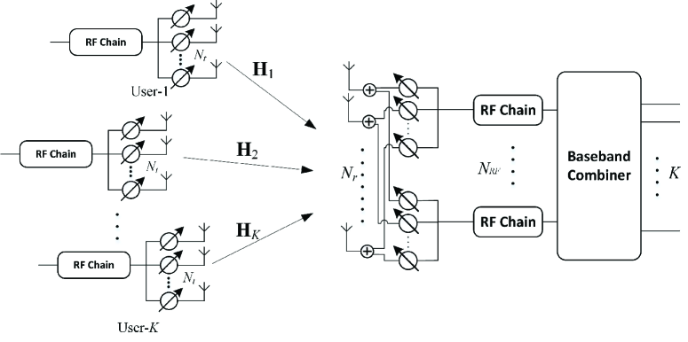
We consider a multiuser mmWave MIMO uplink system as presented in Fig. 2, where a base-station (BS) is equipped with Nrsubscript𝑁𝑟N_{r} antennas and NRFsubscript𝑁𝑅𝐹N_{RF} RF chains and simultaneously serves K𝐾K mobile users. Due to power consumption and hardware limitations, each mobile user has Ntsubscript𝑁𝑡N_{t} antennas and a single RF chain to transmit only one data stream to the BS. We further assume the number of RF chains at the BS is equal to the number of users, i.e. NRF=Ksubscript𝑁𝑅𝐹𝐾N_{RF}=K.

Refer to caption
Figure 2: The multiuser mmWave MIMO system using hybrid precoder and combiner.

Let 𝐟RF,ksubscript𝐟𝑅𝐹𝑘\mathbf{f}_{RF,k} be the analog precoder of the k𝑘k-th user, where each element of 𝐟RF,ksubscript𝐟𝑅𝐹𝑘\mathbf{f}_{RF,k} has a constant magnitude 1Nt1subscript𝑁𝑡\frac{1}{\sqrt{N_{t}}} and low-resolution discrete phases, i.e. 𝐟RF,k(i)subscript𝐟𝑅𝐹𝑘𝑖\mathbf{f}_{RF,k}(i)\in\mathcal{F}, i=1,,Ntfor-all𝑖1subscript𝑁𝑡\forall i=1,\ldots,N_{t}. The transmitted signal of the k𝑘k-th user after precoding can be formulated as

𝐱k=Pk𝐟RF,ksksubscript𝐱𝑘subscript𝑃𝑘subscript𝐟𝑅𝐹𝑘subscript𝑠𝑘\mathbf{x}_{k}=\sqrt{P_{k}}\mathbf{f}_{RF,k}s_{k} (45)

where sksubscript𝑠𝑘s_{k} is the symbol of the k𝑘k-th user, 𝔼{|sk|2}=1𝔼superscriptsubscript𝑠𝑘21\mathbb{E}\{\left|s_{k}\right|^{2}\}=1, and Pksubscript𝑃𝑘P_{k} is the k𝑘k-th user’s transmit power.

Let 𝐇kNr×Nt,k=1,,Kformulae-sequencesubscript𝐇𝑘superscriptsubscript𝑁𝑟subscript𝑁𝑡𝑘1𝐾\mathbf{H}_{k}\in\mathbb{C}^{N_{r}\times N_{t}},~{}k=1,\ldots,K, denote the uplink channel from the k𝑘k-th user to the BS. The received signal at the BS can be written as

𝐫=k=1KPk𝐇k𝐟RF,ksk+𝐧𝐫superscriptsubscript𝑘1𝐾subscript𝑃𝑘subscript𝐇𝑘subscript𝐟𝑅𝐹𝑘subscript𝑠𝑘𝐧\mathbf{r}=\sum_{k=1}^{K}\sqrt{P_{k}}\mathbf{H}_{k}\mathbf{f}_{RF,k}s_{k}+\mathbf{n} (46)

where 𝐧𝒞𝒩(𝟎,σ2𝐈Nr)𝐧𝒞𝒩0superscript𝜎2subscript𝐈subscript𝑁𝑟\mathbf{n}\thicksim\mathcal{CN}(\mathbf{0},\sigma^{2}\mathbf{I}_{N_{r}}) is complex Gaussian noise. The BS first applies an Nr×Ksubscript𝑁𝑟𝐾N_{r}\times K analog combining matrix 𝐖RF[𝐰RF,1𝐰RF,K]subscript𝐖𝑅𝐹delimited-[]subscript𝐰𝑅𝐹1subscript𝐰𝑅𝐹𝐾\mathbf{W}_{RF}\triangleq[\mathbf{w}_{{RF},1}\ldots\mathbf{w}_{{RF},K}] to process the received signal, in which the analog combiner 𝐰RF,ksubscript𝐰𝑅𝐹𝑘\mathbf{w}_{RF,k} corresponding to the k𝑘k-th user is also implemented by low-resolution PSs, i.e. 𝐰RF,k(j)𝒲subscript𝐰𝑅𝐹𝑘𝑗𝒲\mathbf{w}_{{RF},k}(j)\in\mathcal{W}, j=1,,Nr𝑗1subscript𝑁𝑟j=1,\ldots,N_{r}. Then, a baseband digital combiner 𝐰BB,kK×1subscript𝐰𝐵𝐵𝑘superscript𝐾1\mathbf{w}_{{BB},k}\in\mathbb{C}^{K\times 1} is employed to retrieve the information of the k𝑘k-th user. Let 𝐰k𝐖RF𝐰BB,ksubscript𝐰𝑘subscript𝐖𝑅𝐹subscript𝐰𝐵𝐵𝑘\mathbf{w}_{k}\triangleq\mathbf{W}_{RF}\mathbf{w}_{{BB},k} denote the hybrid combiner corresponding to the k𝑘k-th user. After the combining process at the BS, the estimated symbol of the k𝑘k-th user can be expressed as

s^k=Pk𝐰kH𝐇k𝐟RF,ksk+𝐰kHi=1ikKPi𝐇i𝐟RF,isi+𝐰kH𝐧.subscript^𝑠𝑘subscript𝑃𝑘subscriptsuperscript𝐰𝐻𝑘subscript𝐇𝑘subscript𝐟𝑅𝐹𝑘subscript𝑠𝑘subscriptsuperscript𝐰𝐻𝑘superscriptsubscript𝑖1𝑖𝑘𝐾subscript𝑃𝑖subscript𝐇𝑖subscript𝐟𝑅𝐹𝑖subscript𝑠𝑖subscriptsuperscript𝐰𝐻𝑘𝐧\hat{s}_{k}=\sqrt{P_{k}}\mathbf{w}^{H}_{k}\mathbf{H}_{k}\mathbf{f}_{RF,k}s_{k}+\mathbf{w}^{H}_{k}\sum_{\begin{subarray}{c}i=1\\ i\neq k\end{subarray}}^{K}\sqrt{P_{i}}\mathbf{H}_{i}\mathbf{f}_{RF,i}s_{i}+\mathbf{w}^{H}_{k}\mathbf{n}. (47)

Given the received signal at the BS in (47), the signal-to-interference-plus-noise ratio (SINR) of the k𝑘k-th user can be expressed as

γk=Pk𝐰kH𝐇k𝐟RF,k2i=1,ikKPi𝐰kH𝐇i𝐟RF,i2+σ2𝐰k2subscript𝛾𝑘superscriptdelimited-∣∣subscript𝑃𝑘subscriptsuperscript𝐰𝐻𝑘subscript𝐇𝑘subscript𝐟𝑅𝐹𝑘2superscriptsubscriptformulae-sequence𝑖1𝑖𝑘𝐾superscriptdelimited-∣∣subscript𝑃𝑖subscriptsuperscript𝐰𝐻𝑘subscript𝐇𝑖subscript𝐟𝑅𝐹𝑖2superscript𝜎2superscriptnormsubscript𝐰𝑘2\displaystyle\gamma_{k}=\frac{\mid\sqrt{P_{k}}\mathbf{w}^{H}_{k}\mathbf{H}_{k}\mathbf{f}_{RF,k}\mid^{2}}{\sum\limits_{\begin{subarray}{c}i=1,i\neq k\end{subarray}}^{K}\mid\sqrt{P_{i}}\mathbf{w}^{H}_{k}\mathbf{H}_{i}\mathbf{f}_{RF,i}\mid^{2}+\sigma^{2}\parallel\mathbf{w}_{k}\parallel^{2}} (48)

and the achievable sum-rate of the multiuser uplink system is

Ru=k=1Klog(1+γk).subscript𝑅𝑢superscriptsubscript𝑘1𝐾1subscript𝛾𝑘R_{u}=\sum_{k=1}^{K}\log(1+\gamma_{k}). (49)

We aim to jointly design the analog precoders and combiners implemented by low-resolution PSs as well as the digital combiners to maximize the sum-rate of the uplink multiuser system:

{{𝐰RF,k,𝐰BB,k,𝐟RF,k}k=1K}=argmaxk=1Klog(1+γk)superscriptsubscriptsuperscriptsubscript𝐰𝑅𝐹𝑘superscriptsubscript𝐰𝐵𝐵𝑘superscriptsubscript𝐟𝑅𝐹𝑘𝑘1𝐾superscriptsubscript𝑘1𝐾1subscript𝛾𝑘\displaystyle\left\{\left\{\mathbf{w}_{{RF},k}^{\star},\mathbf{w}_{{BB},k}^{\star},\mathbf{f}_{RF,k}^{\star}\right\}_{k=1}^{K}\right\}=\arg\max\sum_{k=1}^{K}\log\left(1+\gamma_{k}\right) (50)
s. t.𝐟RF,k(i),k,i,formulae-sequences. t.subscript𝐟𝑅𝐹𝑘𝑖for-all𝑘𝑖\displaystyle\hskip 28.45274pt\textrm{s. t.}~{}~{}~{}~{}\mathbf{f}_{RF,k}(i)\in\mathcal{F},~{}\forall k,i,
𝐰RF,k(j)𝒲,k,j.subscript𝐰𝑅𝐹𝑘𝑗𝒲for-all𝑘𝑗\displaystyle\hskip 56.9055pt\mathbf{w}_{{RF},k}(j)\in\mathcal{W},~{}\forall k,j.

V-B Low-Resolution Hybrid Precoder and Combiner Design

Obviously, the optimization problem (50) cannot be directly solved. Thus, we adopt an approach similar to [26] and propose to successively design the low-resolution analog beamformer pair for each user, aiming at enhancing the channel gain as well as suppressing the inter-user interference. Then, the baseband combiner at the BS is calculated to further mitigate the interference and maximize the sum-rate.

In particular, for the first user, the analog precoder and combiner pair is designed to maximize the corresponding channel gain, which can be formulated as follows:

{𝐰RF,1,𝐟RF,1}=argmax|𝐰RF,1H𝐇1𝐟RF,1|subscriptsuperscript𝐰𝑅𝐹1subscriptsuperscript𝐟𝑅𝐹1argmaxsubscriptsuperscript𝐰𝐻𝑅𝐹1subscript𝐇1subscript𝐟𝑅𝐹1\displaystyle\hskip 11.38092pt\left\{\mathbf{w}^{\star}_{{RF},1},\mathbf{f}^{\star}_{{RF},1}\right\}=\textrm{arg}\;{\textrm{max}}\left|\mathbf{w}^{H}_{{RF},1}\mathbf{{H}}_{1}\mathbf{f}_{{RF},1}\right| (51)
s. t.𝐟RF,1(i),i=1,,Nt,formulae-sequences. t.subscript𝐟𝑅𝐹1𝑖𝑖1subscript𝑁𝑡\displaystyle\hskip 48.36958pt\textrm{s. t.}~{}~{}~{}\mathbf{f}_{{RF},1}(i)\in\mathcal{F},~{}i=1,\ldots,N_{t},
𝐰RF,1(j)𝒲,j=1,,Nr.formulae-sequencesubscript𝐰𝑅𝐹1𝑗𝒲𝑗1subscript𝑁𝑟\displaystyle\hskip 73.97733pt\mathbf{w}_{{RF},1}(j)\in\mathcal{W},~{}j=1,\ldots,N_{r}.

This analog precoder and combiner design problem can be efficiently solved by the algorithm presented in Sec. III-A when low-resolution PSs are utilized, or the algorithm proposed in Sec. IV if only one-bit resolution PSs are available. Then, the analog precoders 𝐟RF,ksubscript𝐟𝑅𝐹𝑘\mathbf{f}_{RF,k} and combiners 𝐰RF,ksubscript𝐰𝑅𝐹𝑘\mathbf{w}_{{RF},k}, k=2,3,,K𝑘23𝐾k=2,3,\ldots,K, for the remaining K1𝐾1K-1 users are successively designed by an iterative procedure. In each iteration, we attempt to find the analog beamformer pair that suppresses the interference from the users whose analog beamformers have already been determined. To achieve this goal, the channel of the user whose combiner is to be calculated is projected onto the space orthogonal to the collection of previously designed analog combiners. This approach leads to orthogonal analog combiners that suppress the inter-user interference.

Specifically, to design the k𝑘k-th user’s analog beamformer pair, we first extract the orthonormal components 𝐝isubscript𝐝𝑖\mathbf{d}_{i} of the previously determined analog combiners 𝐰RF,isubscriptsuperscript𝐰𝑅𝐹𝑖\mathbf{w}^{\star}_{{RF},i}, i=1,,k1𝑖1𝑘1i=1,\ldots,k-1 by the Gram-Schmidt procedure:

𝐪i=𝐰RF,ij=1i1𝐝jH𝐰RF,i𝐝j,subscript𝐪𝑖subscriptsuperscript𝐰𝑅𝐹𝑖superscriptsubscript𝑗1𝑖1subscriptsuperscript𝐝𝐻𝑗subscriptsuperscript𝐰𝑅𝐹𝑖subscript𝐝𝑗\mathbf{q}_{i}=\mathbf{w}^{\star}_{{RF},i}-\sum\limits_{j=1}^{i-1}\mathbf{d}^{H}_{j}\mathbf{w}^{\star}_{{RF},i}\mathbf{d}_{j}, (52)
𝐝i=𝐪i/𝐪i.subscript𝐝𝑖subscript𝐪𝑖normsubscript𝐪𝑖\mathbf{d}_{i}=\mathbf{q}_{i}/\|\mathbf{q}_{i}\|. (53)

Note that 𝐝1=𝐰RF,1subscript𝐝1subscriptsuperscript𝐰𝑅𝐹1\mathbf{d}_{1}=\mathbf{w}^{\star}_{{RF},1} and 𝐰RF,1subscriptsuperscript𝐰𝑅𝐹1\mathbf{w}^{\star}_{{RF},1} is the analog combiner calculated for the first user. Then, the combiner components are removed from the k𝑘k-th user’s channel to obtain the modified channel 𝐇^ksubscript^𝐇𝑘\mathbf{\widehat{H}}_{k} as

𝐇^k=(𝐈Nri=1k1𝐝i𝐝iH)𝐇k.subscript^𝐇𝑘subscript𝐈subscript𝑁𝑟superscriptsubscript𝑖1𝑘1subscript𝐝𝑖superscriptsubscript𝐝𝑖𝐻subscript𝐇𝑘\mathbf{\widehat{H}}_{k}=\left(\mathbf{I}_{N_{r}}-\sum_{i=1}^{k-1}\mathbf{d}_{i}\mathbf{d}_{i}^{H}\right)\mathbf{H}_{k}. (54)

Finally, based on the modified channel 𝐇^ksubscript^𝐇𝑘\mathbf{\widehat{H}}_{k}, the analog beamformer pair for the k𝑘k-th user is found by solving the following optimization using the algorithms proposed in the previous sections:

{𝐰RF,k,𝐟RF,k}=argmax|𝐰RF,kH𝐇^k𝐟RF,k|subscriptsuperscript𝐰𝑅𝐹𝑘subscriptsuperscript𝐟𝑅𝐹𝑘argmaxsubscriptsuperscript𝐰𝐻𝑅𝐹𝑘subscript^𝐇𝑘subscript𝐟𝑅𝐹𝑘\displaystyle\hskip 11.38092pt\left\{\mathbf{w}^{\star}_{{RF},k},\mathbf{f}^{\star}_{{RF},k}\right\}=\textrm{arg}\;{\textrm{max}}\left|\mathbf{w}^{H}_{{RF},k}\mathbf{\widehat{H}}_{k}\mathbf{f}_{RF,k}\right| (55)
s. t.𝐟RF,k(i),i=1,,Nt,formulae-sequences. t.subscript𝐟𝑅𝐹𝑘𝑖𝑖1subscript𝑁𝑡\displaystyle\hskip 48.36958pt\textrm{s. t.}~{}~{}~{}\mathbf{f}_{RF,k}(i)\in\mathcal{F},~{}i=1,\ldots,N_{t},
𝐰RF,k(j)𝒲,j=1,,Nr.formulae-sequencesubscript𝐰𝑅𝐹𝑘𝑗𝒲𝑗1subscript𝑁𝑟\displaystyle\hskip 73.97733pt\mathbf{w}_{{RF},k}(j)\in\mathcal{W},~{}j=1,\ldots,N_{r}.

After finding the analog beamformers for all users, the effective baseband channel for each user can be obtained as 𝐡kePk(𝐖RF)H𝐇k𝐟RF,ksubscriptsuperscript𝐡𝑒𝑘subscript𝑃𝑘superscriptsubscriptsuperscript𝐖𝑅𝐹𝐻subscript𝐇𝑘subscriptsuperscript𝐟𝑅𝐹𝑘\mathbf{h}^{e}_{k}\triangleq\sqrt{P_{k}}\left(\mathbf{W}^{\star}_{RF}\right)^{H}\mathbf{H}_{k}\mathbf{f}^{\star}_{{RF},k}. Then, a minimum mean square error (MMSE) baseband digital combiner for the k𝑘k-th user is employed to further suppress the interference:

𝐰BB,k=[𝐇e(𝐇e)H+σ2(𝐖RF)H𝐖RF]1𝐡ke,subscriptsuperscript𝐰𝐵𝐵𝑘superscriptdelimited-[]superscript𝐇𝑒superscriptsuperscript𝐇𝑒𝐻superscript𝜎2superscriptsubscriptsuperscript𝐖𝑅𝐹𝐻subscriptsuperscript𝐖𝑅𝐹1subscriptsuperscript𝐡𝑒𝑘\displaystyle\mathbf{w}^{\star}_{{BB},k}=\left[\mathbf{{H}}^{e}(\mathbf{{H}}^{e})^{H}+\sigma^{2}\left(\mathbf{W}^{\star}_{RF}\right)^{H}\mathbf{W}^{\star}_{RF}\right]^{-1}\mathbf{h}^{e}_{k}, (56)

where 𝐇e[𝐡1e,,𝐡Ke]superscript𝐇𝑒subscriptsuperscript𝐡𝑒1subscriptsuperscript𝐡𝑒𝐾\mathbf{H}^{e}\triangleq[\mathbf{h}^{e}_{1},\ldots,\mathbf{h}^{e}_{K}]. The proposed low-resolution hybrid precoder and combiner design for multiuser mmWave systems is summarized in Algorithm 3.

Algorithm 3 Low-Resolution Hybrid Precoder and Combiner Design for Multiuser mmWave Systems
0:  \mathcal{F}, 𝒲𝒲\mathcal{W}, 𝐇ksubscript𝐇𝑘\mathbf{H}_{k}, k=1,,K𝑘1𝐾k=1,\ldots,K.
0:  𝐟RF,ksuperscriptsubscript𝐟𝑅𝐹𝑘\mathbf{f}_{RF,k}^{\star}, 𝐰RF,ksubscriptsuperscript𝐰𝑅𝐹𝑘\mathbf{w}^{\star}_{{RF},k}, 𝐰BB,ksubscriptsuperscript𝐰𝐵𝐵𝑘\mathbf{w}^{\star}_{BB,k}, k=1,,K𝑘1𝐾k=1,\ldots,K.
1:  Obtain 𝐰RF,1subscriptsuperscript𝐰𝑅𝐹1\mathbf{w}^{\star}_{{RF},1} and 𝐟RF,1subscriptsuperscript𝐟𝑅𝐹1\mathbf{f}^{\star}_{{RF},1} for user-1 by solving
{𝐰RF,1,𝐟RF,1}=argmax𝐰RF,1(i)𝒲𝐟RF,1(j)|𝐰RF,1H𝐇1𝐟RF,1|.subscriptsuperscript𝐰𝑅𝐹1superscriptsubscript𝐟𝑅𝐹1argsubscript𝐰𝑅𝐹1𝑖𝒲subscript𝐟𝑅𝐹1𝑗maxsubscriptsuperscript𝐰𝐻𝑅𝐹1subscript𝐇1subscript𝐟𝑅𝐹1\left\{\mathbf{w}^{\star}_{{RF},1},\mathbf{f}_{RF,1}^{\star}\right\}=\textrm{arg}\underset{\begin{subarray}{c}\mathbf{w}_{{RF},1}(i)\in\mathcal{W}\\ \mathbf{f}_{RF,1}(j)\in\mathcal{F}\end{subarray}}{\textrm{max}}|\mathbf{w}^{H}_{{RF},1}\mathbf{H}_{1}\mathbf{f}_{RF,1}|.
2:  𝐝1=𝐰RF,1subscript𝐝1subscriptsuperscript𝐰𝑅𝐹1\mathbf{d}_{1}=\mathbf{w}^{\star}_{{RF},1}.
3:  for k=2:K:𝑘2𝐾k=2:K do
4:     𝐇^k=(𝐈Nri=1k1𝐝i𝐝iH)𝐇ksubscript^𝐇𝑘subscript𝐈subscript𝑁𝑟superscriptsubscript𝑖1𝑘1subscript𝐝𝑖superscriptsubscript𝐝𝑖𝐻subscript𝐇𝑘\mathbf{\widehat{H}}_{k}=\left(\mathbf{I}_{N_{r}}-\sum\limits_{i=1}^{k-1}\mathbf{d}_{i}\mathbf{d}_{i}^{H}\right)\mathbf{H}_{k}.
5:     Obtain 𝐰RF,ksubscriptsuperscript𝐰𝑅𝐹𝑘\mathbf{w}^{\star}_{{RF},k} and 𝐟RF,ksubscriptsuperscript𝐟𝑅𝐹𝑘\mathbf{f}^{\star}_{{RF},k} for user-k𝑘k by solving
{𝐰RF,k,𝐟RF,k}=argmax𝐰RF,k(i)𝒲𝐟RF,k(j)|𝐰RF,kH𝐇^k𝐟RF,k|.subscriptsuperscript𝐰𝑅𝐹𝑘subscriptsuperscript𝐟𝑅𝐹𝑘argsubscript𝐰𝑅𝐹𝑘𝑖𝒲subscript𝐟𝑅𝐹𝑘𝑗maxsubscriptsuperscript𝐰𝐻𝑅𝐹𝑘subscript^𝐇𝑘subscript𝐟𝑅𝐹𝑘\left\{\mathbf{w}^{\star}_{{RF},k},\mathbf{f}^{\star}_{{RF},k}\right\}=\textrm{arg}\underset{\begin{subarray}{c}\mathbf{w}_{{RF},k}(i)\in\mathcal{W}\\ \mathbf{f}_{RF,k}(j)\in\mathcal{F}\end{subarray}}{\textrm{max}}|\mathbf{w}^{H}_{{RF},k}\mathbf{\widehat{H}}_{k}\mathbf{f}_{RF,k}|.
6:     𝐪k=𝐰RF,ki=1k1𝐝iH𝐰RF,k𝐝isubscript𝐪𝑘subscriptsuperscript𝐰𝑅𝐹𝑘superscriptsubscript𝑖1𝑘1subscriptsuperscript𝐝𝐻𝑖subscriptsuperscript𝐰𝑅𝐹𝑘subscript𝐝𝑖\mathbf{q}_{k}=\mathbf{w}^{\star}_{{RF},k}-\sum\limits_{i=1}^{k-1}\mathbf{d}^{H}_{i}\mathbf{w}^{\star}_{{RF},k}\mathbf{d}_{i};
7:     𝐝k=𝐪k/𝐪ksubscript𝐝𝑘subscript𝐪𝑘normsubscript𝐪𝑘\mathbf{d}_{k}=\mathbf{q}_{k}/\|\mathbf{q}_{k}\|.
8:  end for
9:  Obtain digital combiners 𝐰BB,ksubscriptsuperscript𝐰𝐵𝐵𝑘\mathbf{w}^{\star}_{{BB},k}, k=1,,K𝑘1𝐾k=1,\ldots,K, by
𝐰BB,k=[𝐇e(𝐇e)H+σ2(𝐖RF)H𝐖RF]1𝐡ke.subscriptsuperscript𝐰𝐵𝐵𝑘superscriptdelimited-[]superscript𝐇𝑒superscriptsuperscript𝐇𝑒𝐻superscript𝜎2superscriptsubscriptsuperscript𝐖𝑅𝐹𝐻subscriptsuperscript𝐖𝑅𝐹1subscriptsuperscript𝐡𝑒𝑘\mathbf{w}^{\star}_{{BB},k}=\left[\mathbf{H}^{e}(\mathbf{H}^{e})^{H}+\sigma^{2}\left(\mathbf{W}^{\star}_{RF}\right)^{H}\mathbf{W}^{\star}_{RF}\right]^{-1}\mathbf{h}^{e}_{k}.

VI Simulation Results

Refer to caption
Figure 3: Spectral efficiency versus SNR (Nt=64subscript𝑁𝑡64N_{t}=64, Nr=64subscript𝑁𝑟64N_{r}=64, NtRF=NrRF=6superscriptsubscript𝑁𝑡𝑅𝐹superscriptsubscript𝑁𝑟𝑅𝐹6N_{t}^{RF}=N_{r}^{RF}=6, Ns=6subscript𝑁𝑠6N_{s}=6).
Refer to caption
Figure 4: Spectral efficiency versus number of antenna (NtRF=NrRF=4superscriptsubscript𝑁𝑡𝑅𝐹superscriptsubscript𝑁𝑟𝑅𝐹4N_{t}^{RF}=N_{r}^{RF}=4, Ns=4subscript𝑁𝑠4N_{s}=4, SNR = 202020dB).
Refer to caption
Figure 5: Spectral efficiency versus number of iteration (Nt=64,Nr=64formulae-sequencesubscript𝑁𝑡64subscript𝑁𝑟64N_{t}=64,N_{r}=64, NtRF=NrRF=4superscriptsubscript𝑁𝑡𝑅𝐹superscriptsubscript𝑁𝑟𝑅𝐹4N_{t}^{RF}=N_{r}^{RF}=4, Ns=4subscript𝑁𝑠4N_{s}=4, SNR = 202020dB).
Refer to caption
Figure 6: Spectral efficiency versus resolution of PSs (Nt=64subscript𝑁𝑡64N_{t}=64, Nr=64subscript𝑁𝑟64N_{r}=64, NtRF=NrRF=4superscriptsubscript𝑁𝑡𝑅𝐹superscriptsubscript𝑁𝑟𝑅𝐹4N_{t}^{RF}=N_{r}^{RF}=4, Ns=4subscript𝑁𝑠4N_{s}=4, SNR=20SNR20\mathrm{SNR}=20dB).
Refer to caption
Figure 7: Spectral efficiency versus SNR (Nt=8subscript𝑁𝑡8N_{t}=8, Nr=8subscript𝑁𝑟8N_{r}=8, Ns=1subscript𝑁𝑠1N_{s}=1, B=1𝐵1B=1).

In this section, we provide simulation results for the proposed joint hybrid precoder and combiner designs with low-resolution PSs for point-to-point mmWave systems as well as multiuser mmWave systems. MmWave channels are expected to be sparse and have a limited number of propagation paths. In the simulations, we adopt a geometric channel model with L𝐿L paths [32]. In particular, the discrete-time narrow-band mmWave channel 𝐇𝐇\mathbf{H} is formulated as

𝐇=NtNrLi=1Lαi𝐚r(θir)𝐚t(θit)H𝐇subscript𝑁𝑡subscript𝑁𝑟𝐿superscriptsubscript𝑖1𝐿subscript𝛼𝑖subscript𝐚𝑟superscriptsubscript𝜃𝑖𝑟subscript𝐚𝑡superscriptsuperscriptsubscript𝜃𝑖𝑡𝐻\mathbf{H}=\sqrt{\frac{N_{t}N_{r}}{L}}\sum_{i=1}^{L}\alpha_{i}\mathbf{a}_{r}(\theta_{i}^{r})\mathbf{a}_{t}(\theta_{i}^{t})^{H} (57)

where αi𝒞𝒩(0,1L)subscript𝛼𝑖𝒞𝒩01𝐿\alpha_{i}\thicksim\mathcal{CN}(0,\frac{1}{L}) are the independent and identically distributed complex gains of the i𝑖i-th propagation path (ray) θitsuperscriptsubscript𝜃𝑖𝑡\theta_{i}^{t} and θirsuperscriptsubscript𝜃𝑖𝑟\theta_{i}^{r} [π2,π2]absent𝜋2𝜋2\in[-\frac{\pi}{2},\frac{\pi}{2}] are the angles of departure (AoD) and the angles of arrival (AoA), respectively. Finally, the array response vectors 𝐚t(θt)subscript𝐚𝑡superscript𝜃𝑡\mathbf{a}_{t}(\theta^{t}) and 𝐚r(θr)subscript𝐚𝑟superscript𝜃𝑟\mathbf{a}_{r}(\theta^{r}) depend on the antenna array geometry. We assume that the commonly used uniform linear arrays (ULAs) are employed, and the transmit antenna array response vector 𝐚t(θt)subscript𝐚𝑡superscript𝜃𝑡\mathbf{a}_{t}(\theta^{t}) and the receive antenna array response vector 𝐚r(θr)subscript𝐚𝑟superscript𝜃𝑟\mathbf{a}_{r}(\theta^{r}) can be written as

𝐚t(θt)=1Nt[1,ej2πλdsin(θt),,ej(Nt1)2πλdsin(θt)]T,subscript𝐚𝑡superscript𝜃𝑡1subscript𝑁𝑡superscript1superscript𝑒𝑗2𝜋𝜆𝑑superscript𝜃𝑡superscript𝑒𝑗subscript𝑁𝑡12𝜋𝜆𝑑superscript𝜃𝑡𝑇\mathbf{a}_{t}(\theta^{t})=\frac{1}{\sqrt{N_{t}}}[1,{e}^{j\frac{2\pi}{\lambda}d\sin(\theta^{t})},\ldots,{e}^{j(N_{t}-1)\frac{2\pi}{\lambda}d\sin(\theta^{t})}]^{T}, (58)
𝐚r(θr)=1Nr[1,ej2πλdsin(θr),,ej(Nr1)2πλdsin(θr)]T,subscript𝐚𝑟superscript𝜃𝑟1subscript𝑁𝑟superscript1superscript𝑒𝑗2𝜋𝜆𝑑superscript𝜃𝑟superscript𝑒𝑗subscript𝑁𝑟12𝜋𝜆𝑑superscript𝜃𝑟𝑇\mathbf{a}_{r}(\theta^{r})=\frac{1}{\sqrt{N_{r}}}[1,{e}^{j\frac{2\pi}{\lambda}d\sin(\theta^{r})},\ldots,{e}^{j(N_{r}-1)\frac{2\pi}{\lambda}d\sin(\theta^{r})}]^{T}, (59)

respectively, where λ𝜆\lambda is the signal wavelength, and d𝑑d is the distance between antenna elements. In the following simulations, we consider an environment with L=6𝐿6L=6 scatterers between the transmitter and the receiver. The antenna spacing is d=λ2𝑑𝜆2d=\frac{\lambda}{2}.

VI-A Simulation Results of a Point-to-Point mmWave System

We first consider a point-to-point mmWave communication system, in which the transmitter and receiver are both equipped with 646464-antenna ULAs. The number of RF chains at the transmitter and receiver are NtRF=NrRF=6superscriptsubscript𝑁𝑡𝑅𝐹superscriptsubscript𝑁𝑟𝑅𝐹6N_{t}^{RF}=N_{r}^{RF}=6, so the number of data streams is also assumed to be Ns=6subscript𝑁𝑠6N_{s}=6.

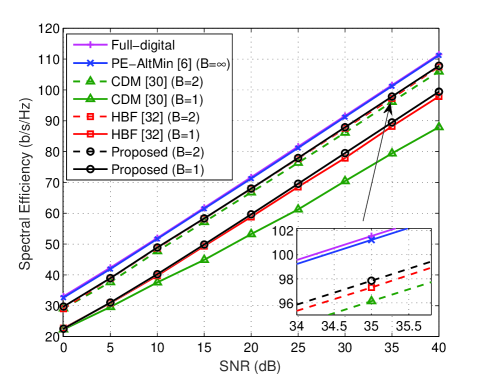
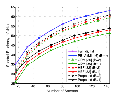
Fig. 4 shows the average spectral efficiency versus SNR over 106superscript10610^{6} channel realizations. We evaluate the spectral efficiency of the algorithm proposed in Sec. III for the case of 2-bit (B=2𝐵2B=2) resolution PSs and the algorithm proposed in Sec. IV for the case of 1-bit (B=1𝐵1B=1) resolution PSs. For comparison purposes, we also plot the spectral efficiency of two state-of-the-art low-resolution hybrid beamformer designs: the coordinate descent method (CDM) algorithm in [30] and the hybrid beamforming (HBF) algorithm in [32]. To the best of our knowledge, the algorithm in [32] achieves the best performance with low-resolution PSs in the existing literature. The performance of a fully digital approach using SVD-based beamforming and the hybrid beamforming scheme with infinite-resolution (B=𝐵B=\infty) PSs using the phase extraction (PE-AltMin) algorithm in [6] are also included as performance benchmarks. Fig. 4 illustrates that the proposed algorithm outperforms the competitors, particularly for the case of 1-bit resolution PSs. Moreover, it can be observed that the proposed algorithm with B=2𝐵2B=2 achieves performance close to optimal full-digital beamforming and hybrid beamforming with infinite-resolution PSs. For additional simulation validation, Fig. 4 illustrates the spectral efficiency versus the number of antennas and similar conclusions can be drawn.

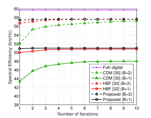
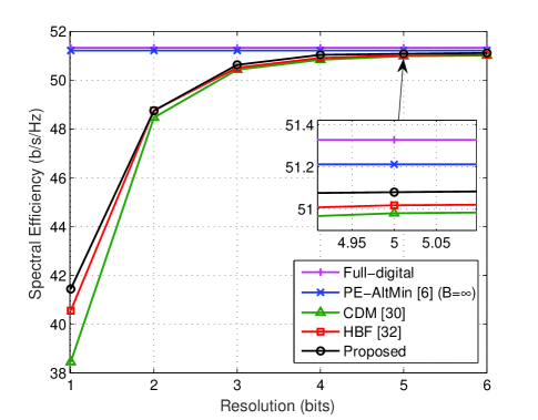
In order to illustrate the convergence of the proposed algorithm, we show the spectral efficiency versus the number of iterations in Fig. 6, which also includes other algorithms for comparison. It is observed that our proposed algorithms converge faster than the other two iterative schemes, which is a highly favorable property. In Fig. 6, we show the spectral efficiency as a function of B𝐵B to illustrate the impact of the resolution of PSs on the spectral efficiency. As expected, increasing the PS resolution will improve the system performance, but using only B=3𝐵3B=3 bits is sufficient to closely approach the performance of the ideal unquantized case. Beyond B=3𝐵3B=3, the additional cost and complexity associated with using higher-resolution PSs is not warranted given the very marginal increase in spectral efficiency. Moreover, our proposed algorithms outperform the other two low-resolution beamforming methods for all PS resolutions.

Refer to caption
Figure 8: Spectral efficiency versus SNR (Nt=64subscript𝑁𝑡64N_{t}=64, Nr=16subscript𝑁𝑟16N_{r}=16, NtRF=4superscriptsubscript𝑁𝑡𝑅𝐹4N_{t}^{RF}=4, K=4𝐾4K=4).
Refer to caption
Figure 9: Spectral efficiency versus K𝐾K (Nt=64,Nr=16formulae-sequencesubscript𝑁𝑡64subscript𝑁𝑟16N_{t}=64,N_{r}=16, NtRF=Ksuperscriptsubscript𝑁𝑡𝑅𝐹𝐾N_{t}^{RF}=K, SNR = 202020dB).

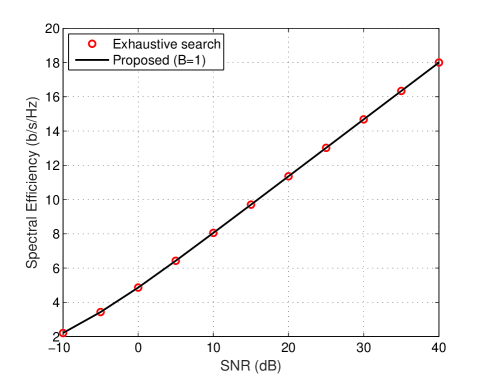
To examine the impact of the approximations used in deriving the proposed one-bit resolution hybrid beamformer scheme, in Fig. 7 we compare it with the optimal exhaustive search approach. The number of antennas at both transmitter and receiver is chosen to be 8 and the number of data streams is Ns=1subscript𝑁𝑠1N_{s}=1. A relatively simple case is examined here due to the exponential complexity of the exhaustive search method. We see from Fig. 7 that the spectral efficiency achieved by the proposed algorithm is the same as that of the optimal exhaustive search method, suggesting that the proposed hybrid beamforming algorithm with one-bit resolution PSs can provide optimal or near-optimal performance.

VI-B Simulation Results of a Multiuser mmWave System

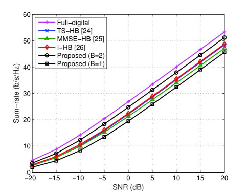
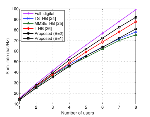
Next, we evaluate the performance of the proposed low-resolution beamformer algorithm in a multiuser uplink system. We assume there are K=4𝐾4K=4 users, each of which is equipped with Nt=16subscript𝑁𝑡16N_{t}=16 antennas and only one RF chain to transmit a single data stream. The BS has Nr=64subscript𝑁𝑟64N_{r}=64 antennas and NrRF=4superscriptsubscript𝑁𝑟𝑅𝐹4N_{r}^{RF}=4 RF chains. Fig. 9 illustrates the sum-rate versus SNR for various hybrid beamformer designs. In particular, we include three state-of-the-art multiuser hybrid beamforming approaches for comparison: i) two-stage hybrid beamforming (TS-HB) in [24], ii) MMSE-based hybrid beamforming (MMSE-HB) in [25], and iii) iterative hybrid beamforming (I-HB) in [26]. All three algorithms are codebook-based approaches and the size of the beamsteering codebook is set at 323232 (i.e. B=5𝐵5B=5 quantization bits) for fairness of the comparison. It can be observed from Fig. 9 that our proposed low-resolution hybrid beamforming design outperforms the other three algorithms using only 2-bit resolution PSs. Moreover, the performance with 1-bit resolution PSs is also comparable. Fig. 9 further shows the sum-rate versus the number of users K𝐾K. From Fig. 9, we see that our proposed algorithm with 2-bit resolution PSs always outperforms the other codebook-based algorithms. Furthermore, even with 1-bit resolution PSs, the proposed algorithm can still achieve competitive performance compared with the TS-HB and MMSE-HB approaches when K>5𝐾5K>5.

VII Conclusions

This paper considered the problem of hybrid precoder and combiner design for mmWave MIMO systems with low-resolution quantized PSs. We proposed an efficient iterative algorithm which successively designs the low-resolution analog precoder and combiner pair for each data stream. Then, the digital precoder and combiner were computed based on the obtained effective baseband channel to further enhance the spectral efficiency. The design of low-resolution hybrid beamformers for multiuser MIMO communication systems was also investigated. Simulation results verified the effectiveness of the proposed algorithms, particularly for scenarios in which one-bit resolution phase shifters are used.

Appendix A Proof of Proposition 1

The optimization problem (19) can be equivalently formulated as

max|1NtNrj=1Nrejφjli=1Ntejϑil𝐐l(j,i)|.max1subscript𝑁𝑡subscript𝑁𝑟superscriptsubscript𝑗1subscript𝑁𝑟superscript𝑒𝑗superscriptsubscript𝜑𝑗𝑙superscriptsubscript𝑖1subscript𝑁𝑡superscript𝑒𝑗superscriptsubscriptitalic-ϑ𝑖𝑙subscript𝐐𝑙𝑗𝑖{\textrm{max}}\left|\frac{1}{\sqrt{N_{t}N_{r}}}\sum_{j=1}^{N_{r}}e^{j\varphi_{j}^{l}}\sum_{i=1}^{N_{t}}e^{j\vartheta_{i}^{l}}\mathbf{Q}_{l}(j,i)\right|. (60)

By discarding the constant coefficient 1/NtNr1subscript𝑁𝑡subscript𝑁𝑟1/\sqrt{N_{t}N_{r}}, (60) can be further transformed as

max|j=1Nrejφjl{ejϑil𝐐l(j,i)+uiNtejϑul𝐐l(j,u)}|.maxsuperscriptsubscript𝑗1subscript𝑁𝑟superscript𝑒𝑗superscriptsubscript𝜑𝑗𝑙superscript𝑒𝑗superscriptsubscriptitalic-ϑ𝑖𝑙subscript𝐐𝑙𝑗𝑖superscriptsubscript𝑢𝑖subscript𝑁𝑡superscript𝑒𝑗superscriptsubscriptitalic-ϑ𝑢𝑙subscript𝐐𝑙𝑗𝑢{\textrm{max}}\left|\sum_{j=1}^{N_{r}}e^{j\varphi_{j}^{l}}\left\{e^{j\vartheta_{i}^{l}}\mathbf{Q}_{l}(j,i)+\sum_{u\neq i}^{N_{t}}e^{j\vartheta_{u}^{l}}\mathbf{Q}_{l}(j,u)\right\}\right|. (61)

Since the term ejϑilsuperscript𝑒𝑗superscriptsubscriptitalic-ϑ𝑖𝑙e^{j\vartheta_{i}^{l}} does not involve the summation index j𝑗j, it can be put outside the first summation, resulting in

max|ejϑilj=1Nrejφjl𝐐l(j,i)+j=1NrejφjluiNtejϑul𝐐l(j,u)|.maxsuperscript𝑒𝑗superscriptsubscriptitalic-ϑ𝑖𝑙superscriptsubscript𝑗1subscript𝑁𝑟superscript𝑒𝑗superscriptsubscript𝜑𝑗𝑙subscript𝐐𝑙𝑗𝑖superscriptsubscript𝑗1subscript𝑁𝑟superscript𝑒𝑗superscriptsubscript𝜑𝑗𝑙superscriptsubscript𝑢𝑖subscript𝑁𝑡superscript𝑒𝑗superscriptsubscriptitalic-ϑ𝑢𝑙subscript𝐐𝑙𝑗𝑢{\textrm{max}}\left|e^{j\vartheta_{i}^{l}}\sum_{j=1}^{N_{r}}e^{j\varphi_{j}^{l}}\mathbf{Q}_{l}(j,i)+\sum_{j=1}^{N_{r}}e^{j\varphi_{j}^{l}}\sum_{u\neq i}^{N_{t}}e^{j\vartheta_{u}^{l}}\mathbf{Q}_{l}(j,u)\right|. (62)

Obviously, the optimal value of ϑilsuperscriptsubscriptitalic-ϑ𝑖𝑙\vartheta_{i}^{l} makes the phases of the first and second term equal to obtain the largest amplitude, and (20) is proved. \blacksquare

References

  • [1] Z. Pi and F. Khan, “An introduction to millimeter-wave mobile broadband systems,” IEEE Commun. Mag., vol. 49, no. 6, pp. 101-107, June 2011.
  • [2] T. Rappaport, S. Sun, R. Mayzus, H. Zhao, Y. Azar, K. Wang, G. N. Wong, J. K. Schulz, M. Samimi, and F. Gutierrez “Millimeter wave mobile communications for 5G cellular: It will work!” IEEE Access, vol. 1, pp. 335-349, 2013.
  • [3] A. Lee Swindlehurst, E. Ayanoglu, P. Heydari, and F. Capolino, “Millimeter-wave massive MIMO: The next wireless revolution?” IEEE Commun. Mag., vol. 52, no. 9, pp. 56-62, Sept. 2014.
  • [4] T. S. Rappapport, G. R. MacCartney, M. K. Samimi, and S. Sun, “Wideband millimeter-wave propagation measurements and channel models for future wireless communication system design”, IEEE Trans. Commun., vol. 63, no. 9, pp. 3029-3056, Sept. 2015.
  • [5] R. W. Heath Jr., N. González-Prelcic, S. Rangan, W. Roh, and A. M. Sayeed, “An overview of signal processing techniques for millimeter wave MIMO systems,” IEEE J. Sel. Topics Signal Process., vol. 10, no. 3, pp. 436-453, April 2016.
  • [6] X. Yu, J.-C. Shen, J. Zhang, and K. B. Letaief, “Alternating minimization algorithms for hybrid precoding in millimeter wave MIMO systems,” IEEE J. Sel. Topics Signal Process., vol. 10, no. 3, pp. 485-500, April 2016.
  • [7] C. Rusu, R. Méndez-Rial, N. González-Prelcic, and R. W. Heath Jr., “Low complexity hybrid precoding strategies for millimeter wave communication systems,” IEEE Trans. Wireless Commun., vol. 15, no. 12, pp. 8380-8393, Sept. 2016.
  • [8] R. López-Valcarce, N. González-Prelcic, C. Rusu, and R. W. Heath Jr., “Hybrid precoders and combiners for mmWave MIMO systems with per-antenna power constraints.” in Proc. IEEE Global Communication Conference (GLOBECOM), Washington, DC, Dec. 2016, pp. 1-6.
  • [9] C.-E. Chen, “An iterative hybrid transceiver design algorithm for millimeter wave MIMO systems,” IEEE Wireless Commun. Lett., vol. 4, no. 3, pp. 285-288, June 2015.
  • [10] W. Ni, X. Dong, and W.-S. Lu, “Near-optimal hybrid processing for massive MIMO systems via matrix decomposition,” IEEE Trans. Signal Process., vol. 65, no. 15, pp. 3922-3933, Aug. 2017.
  • [11] X. Gao, L. Dai, S. Han, C.-L. I, and R. W. Heath Jr., “Energy-efficient hybrid analog and digital precoding for mmWave MIMO systems with large antenna arrays,” IEEE J. Sel. Areas Commun., vol. 34, no. 4, pp. 998-1009, April 2016.
  • [12] L. Dai, X. Gao, J. Quan, S. Han, and C.-L. I, “Near-optimal hybrid analog and digital precoding for downlink mmWave massive MIMO systems”, in Proc. IEEE Int. Conf. Commun. (ICC), London, UK, June 2015, pp. 1334-1339.
  • [13] S. He, C. Qi, Y. Wu, and Y. Huang, “Energy-efficient transceiver design for hybrid sub-array architecture MIMO systems,” IEEE Access, vol. 4, pp. 9895-9905, 2016.
  • [14] O. E. Ayach, S. Rajagopal, S. Abu-Surra, Z. Pi, and R. W. Heath Jr., “Spatially sparse precoding in millimeter wave MIMO systems,” IEEE Trans. Wireless Commun., vol. 13, no. 3, pp. 1499-1513, Mar. 2014.
  • [15] A. Alkhateeb, O. El Ayach, G. Leus, and R. W. Heath Jr., “Channel estimation and hybrid precoding for millimeter wave cellular systems,” IEEE J. Sel. Topics Signal Process., vol. 8, no. 5, pp. 831-846, Oct. 2014.
  • [16] C. Rusu, R. Méndez-Rial, N. González-Prelcic, and R. W. Heath Jr., “Low complexity hybrid sparse precoding and combining in millimeter wave MIMO systems,” IEEE Int. Conf. on Commun. (ICC), London, UK, June 2015, pp. 1340-1345.
  • [17] J.-C. Chen, “Efficient codebook-based beamforming algorithm for millimeter-wave massive MIMO systems,” IEEE Trans. Veh. Technol., to Appear.
  • [18] X. Gao, L. Dai, C. Yuen, and Z. Wang, “Turbo-like beamforming based on Tabu search algorithm for millimeter-wave massive MIMO systems,” IEEE Trans. Veh. Technol., vol. 65, no. 7, pp. 5731-5737, July 2016.
  • [19] S. Han, C.-L. I, Z. Xu, and C. Rowell, “Large-scale antenna systems with hybrid analog and digital beamforming for millimeter wave 5G,” IEEE Commun. Mag., vol. 53, no. 1, pp. 186-194, Jan. 2015.
  • [20] A. Li and C. Masouros, “Hybrid analog-digital millimeter-wave MU-MIMO transmission with virtual path selection,” IEEE Commun. Lett., vol. 21, no. 2, pp. 438-441, Feb. 2017.
  • [21] L. Liang, W. Xu, and X. Dong, “Low-complexity hybrid precoding in massive multiuser MIMO systems,” IEEE Wireless Commun. Lett., vol. 3, no. 6, pp. 653-656, Dec. 2014.
  • [22] A. Li and C. Masouros, “Hybrid precoding and combining design for millimeter-wave multi-user MIMO based on SVD,” IEEE Int. Conf. on Commun. (ICC), Paris, France, May 2017, pp. 1-6.
  • [23] M. Kim and Y. H. Lee, “MSE-based hybrid RF/baseband processing for millimeter-wave communication systems in MIMO interference channels,” IEEE Trans. Veh. Technol., vol. 64, no. 6, pp. 2714-2720, June 2015.
  • [24] A. Alkhateeb, G. Leus, and R. W. Heath Jr., “Limited feedback hybrid precoding for multi-user millimeter wave systems,” IEEE Trans. Wireless Commun., vol. 14, no. 11, pp. 6481-6494, Nov. 2015.
  • [25] D. H. N. Nguyen, L. B. Le, and T. Le-Ngoc, “Hybrid MMSE precoding for mmWave multiuser MIMO systems,” IEEE Int. Conf. on Commun. (ICC), Kuala Lumpur, Malaysia, May 2016.
  • [26] Z. Wang, M. Li, X. Tian, and Q. Liu, “Iterative hybrid precoder and combiner design for mmWave multiuser MIMO systems,” IEEE Commun. Lett., vol. 21, no. 7, pp. 1581-1584, July 2017.
  • [27] T. E. Bogale, L. B. Le, A. Haghighat, and L. Vandendorpe, “On the number of RF chains and phase shifters, and scheduling design with hybrid analog-digital beamforming,” IEEE Trans. Wireless Commun., vol. 15, no. 5, pp. 3311-3326, May 2016.
  • [28] A. S. Y. Poon and M. Taghivand, “Supporting and enabling circuits for antenna arrays in wireless communications,” Proc. IEEE, vol. 100, no. 7, pp. 2207-2218, July 2012.
  • [29] R. Méndez-Rial, C. Rusu, N. González-Prelcic, and A. Alkhateeb, “Hybrid MIMO architectures for millimeter wave communications: Phase shifters or switches?”, IEEE Access, vol. 4, pp. 247-267, March 2016.
  • [30] J.-C. Chen, “Hyrbrid beamforming with discrete phase shifters for millimeter-wave massive MIMO systems,” IEEE Trans. Veh. Technol., to Appear.
  • [31] F. Sohrabi and W. Yu, “Hybrid beamforming with finite-resolution phase shifters for large-scale MIMO systems,” in Proc. IEEE Workshop Signal Process. Adv. Wireless Commun. (SPAWC), Stockholm, Sweden, June 2015, pp. 136-140.
  • [32] F. Sohrabi and W. Yu, “Hybrid digital and analog beamforming design for large-scale antenna arrays,” IEEE J. Sel. Topics Signal Process., vol. 10, no. 3, pp. 501-513, April 2016.
  • [33] G. N. Karystinos and D. A. Pados, “Rank-2-optimal adaptive design of binary spreading codes,” IEEE Trans. Inf. Theory, vol. 53, no. 9, pp. 3075-3080, Sept. 2007.
  • [34] G. H. Golub and C. F. Van Loan, Matrix Computations. Baltimore, USA: JHU Press, 2012.