Continuum Deformation of a Multiple Quadcopter Payload Delivery Team without Inter-Agent Communication
Abstract
This paper proposes continuum deformation as a strategy for controlling the collective motion of a multiple quadcopter system (MQS) carrying a common payload. Continuum deformation allows expansion and contraction of inter-agent distances in a motion plane to follow desired motions of three team leaders. The remaining quadcopter followers establish the desired continuum deformation only by knowing leaders’ positions at desired sample time waypoints without the need for inter-agent communication over the intermediate intervals. Each quadcopter applies a linear-quadratic Gaussian (LQG) controller to track the desired trajectory given by the continuum deformation in the presence of disturbance and measurement noise. Results of simulated cooperative aerial payload transport in the presence of uncertainty illustrate application of continuum deformation for coordinated transport through a narrow channel.
I Introduction
Cooperative control of multiple unmanned aerial vehicles (UAVs) has been an active area of research over the past two decades. Formation flightproud1999close ; fax2004information , air traffic control paterno1998formal , transportation engineering michael2011cooperative , aerobiological sampling over agricultural lands schmale2008development , cooperative manipulation michael2009kinematics and general team-based surveillance are some applications of cooperative control. A UAV team can improve mission efficiency, reduce cost, and offer increased resilience to failures including individual UAV loss. Group cooperation also improves fault detection and ability for the team to recover from anomaly conditions bahceci2003review ; bazoula2008formation ; murray2007recent . Consensus olfati2007consensus ; ren2009distributed , containment control cao2011distributed ; li2012distributed and partial differential equation (PDE) methods frihauf2011leader offer schemes to coordinate large-scale multi-UAV teams.
Cooperative payload transport, grasping and manipulation using multiple UAVs are applications that require UAVs to manage total forces and moments applied to external object(s) along with their collective motions. Manipulation can be used to achieve perching or deploy/pickup payloads, or the cooperative team can carry slung loads bernard2011autonomous ; bernard2008slung . Swing-free trajectory tracking is demonstrated by a single quadcopter carrying a payload in palunko2012trajectory . Aerial manipulation using a single quadcopter is studied in kim2013aerial . Modeling and control of multiple UAVs deployed for cooperative manipulation are investigated in michael2011cooperative ; mellinger2011design ; kim2013aerial ; michael2009kinematics ; sreenath2013dynamics , while cooperative grasping of a payload using multiple UAVs is studied in mellinger2013cooperative ; mellinger2011design . Adaptive control for a slung load transport mission using a single rotorcraft is studied in bisgaard2010adaptive ; potter2011reducing ; dai2014adaptive . Stability of slung load transport carrying by a multiple single-rotor helicopters is investigated in pounds2011grasping , while an inverse kinematics formulation for aerial payload transport is presented in jiang2013inverse .
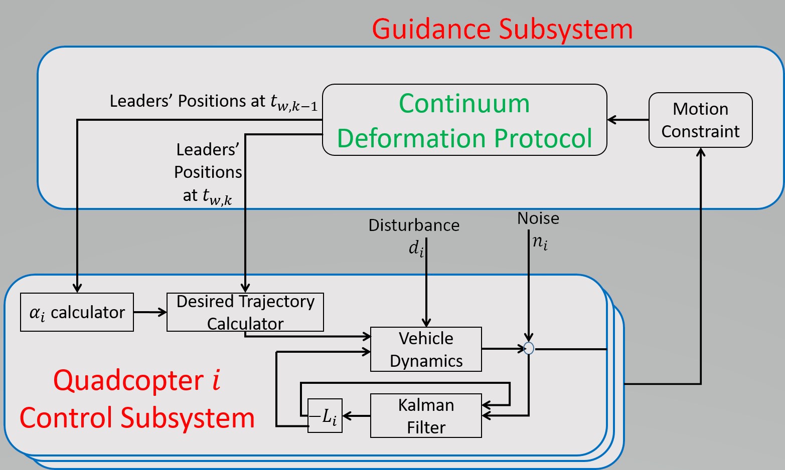
This paper proposes a novel control strategy (Fig. 1) for cooperative aerial payload transport in the presence of uncertainty. A central guidance and control module manages leader UAV motions while follower UAV motions are efficiently regulated through continuum deformation. A linear quadratic Gaussian (LQG) controller boyd1991linear combining a linear quadratic controller and a Kalman estimator kalman1960new ; brown1997introduction offers robust trajectory tracking by each quadcopter. The guidance subsystem applies the recently proposed continuum deformation algorithm to achieve robust collective motion of quadcopter team during payload transport rastgoftar2016continuum ; rastgoftarasymptotic . This protocol treats quadcopters as particles of a continuum and allows expansion and contraction of inter-agent distances. For continuum deformation in a plane, i.e., constant-altitude quadcopter motion, a leader-follower model designates three quadcopter leaders at the vertices of a triangle, called the leading triangle. The remaining quadcopters fly inside the leading triangle and are modeled as followers.
Application of continuum deformation to payload transport offers the following advantages:
-
1.
Scalability: The total number of quadcopters participating in a payload delivery mission can be chosen sufficiently high that each quadcopter in a multi-quadcopter system (MQS) can carry a modest payload weight.
-
2.
Minimal Inter-Agent Communication: Section V will describe how a desired MQS formation can be achieved without regular inter-agent communication. A follower quadcopter does not require position information of other follow quadcopters to learn the desired continuum deformation. Only leaders’ positions at waypoint arrival times must communicated across the team, minimizing communication costs and bandwidth requirements.
-
3.
Negotiating obstacle-laden environments: Because quadcopters are treated as particles of a continuum and inter-agent distances can be expanded or contracted via the continuum deformation strategy, the team can navigate constrained environments including passing through a narrow channel. This capability will be demonstrated in simulation below.
-
4.
Collision Avoidance: Because the proposed continuum deformation protocol is guided by leaders at the vertices of a triangle and followers are all inside the leading triangle, collisions with obstacles can be avoided by choosing appropriate trajectories for leaders’ motions. Due to the nonsingularity of continuum deformation, inter-agent collision can be avoided throughout the mission.
This article is organized as follows. First, multi-agent system continuum deformation is summarized in Section II. Application to MQS continuum deformation for a cooperative payload delivery mission is described in Section III. The dynamics model of a single quadcopter as well as LQG controller design is described in Section IV, while Section V describes the guidance subsystem and formulates follower quadcopter desired trajectories learned without inter-agent communication. An aerial MQS payload transport case study in which the MQS negotiates a narrow channel is provided in Section VI followed by concluding remarks in Section VII.
II Continuum Deformation of Multi-Agent Systems
Let a continuum deformation in a motion space be defined by
| (1) |
where is the Jacobian matrix, is a rigid-body displacement vector, and
| (2) |
is called the desired position of agent given by a homogeneous deformation. Without loss of generality, a continuum deformation in the plane is considered in this article, therefore,
For continuum deformation in a motion space, three leaders are placed at the vertices of a leading triangle and defines leader index numbers. Additionally, followers are located inside the leading triangle and defines follower index numbers. Elements of the Jacobian matrix and rigid-body displacement vector can be uniquely related to leaders’ positions by rastgoftar2016continuum ; rastgoftarasymptotic ; rastgoftar2017continuum
| (3) |
where "" is the Kronecker product symbol, is the identity matrix, and is the one-entry vector,
| (4) |
| (5) |
and
| (6) |
Note that the matrix is nonsingular if leader positions satisfy the following rank condition rastgoftar2016continuum ; rastgoftarasymptotic ; rastgoftar2017continuum :
| (7) |
The continuum deformation defined in Eq. (2) is called homogeneous deformation because the Jacobian matrix is only time-varying but is not spatially-varying.
Invariant Parameters of a Homogeneous Deformation: Under a homogeneous deformation, the position of an agent can be expressed as the linear combination of leaders’ positions,
| (8) |
where is unique and obtained from
| (9) |
Parameters , , remain unchanged at any time , if satisfies Eq. (2) (). Note that
| (10) |
and when agent is inside the leading triangle.
III Problem Statement
Consider an MQS consisting of vehicles moving collectively in a motion space. The MQS is deployed for payload aerial transport and it offers the ability of negotiating a narrow channel or other spatially-constrained environment. This paper proposes the architecture shown in Fig. 1 for guidance and control of the cooperative MQS.
The guidance system applies principles of continuum mechanics lai2009introduction to assign desired waypoints at certain sampling times given constraints of the mission. Note that desired waypoints provided by the guidance system are defined by a homogeneous deformation. The desired homogeneous deformation is formulated based on positions of three leader quadcopters at the vertices of the leading triangle as described above. The remaining quadcopters are followers acquiring the desired homogeneous deformation only by knowing leader waypoints at known sample times , , , , . Section V describes how the MQS desired formation given by a homogeneous deformation can be learned by followers without communication during intermediate time intervals , , , , .
The control system of an individual quadcopter uses a degree of freedom (DOF) motion model. For control of each quadcopter, the order quadcopter dynamics model is linearized around the desired state. Given the desired trajectory of quadcopter and the tension force exerted by a connecting cable, the desired state of quadcopter , , is specified as described in Section IV.3.1. An LQG controller offers robust tracking of the desired state given disturbances and measurement noise. The subsequent case study shows how an MQS consisting of quadcopters can cooperatively carrying a payload from an open area through a narrow channel.
IV Quadcopter Dynamics Model
IV.1 Kinematics
IV.1.1 Quadcopter Centroid Velocity and Acceleration
The centroid position of quadcopter is expressed with respect to an inertial frame attached to the ground (Earth):
| (11) |
Therefore, velocity and acceleration of quadcopter is given by
| (12) |
| (13) |
IV.1.2 Quadcopter Centroid Angular Velocity and Acceleration
Let , , be the "roll", "pitch", and "yaw" angles of quadcopter , then angular velocity of quadcopter is assigned by using the "3-2-1" standard Quadcopter angular velocity is given by
| (14) |
where
Quadcopter angular velocity given in Eq. (14) can be rewritten in the following component-wise form:
| (15) |
where
| (16) |
The angular acceleration of quadcopter is given by
| (17) |
IV.2 Quadcopter Equations of Motion
By applying Newton’s second law, the quadcopter equations of motion become
| (18) |
where is the mass of quadcopter , is the gravitational acceleration, is the tension force in the cord connecting quadcopter to the payload, and is the total thrust generated by quadcopter ’s rotors,
, , represent aerodynamics parameters. Expressing with respect to , , and ,
| (19) |
equations of motion of quadcopter can be rewritten in the following form:
| (20) |
where
IV.3 Quadcopter LQG Control Law
An LQG controller offers robust tracking of the desired state for each quadcopter in the presence of uncertainty. Section IV.3.1 formulates the desired state and input given a desired trajectory assigned by continuum deformation. An LQG controller is then designed in Section IV.3.2 to track the desired position defined by the continuum deformation in the presence of uncertainty.
IV.3.1 Assigning Desired State and Desired Input
The , , , , , and of desired state,
are obtained from the guidance system by applying the proposed continuum deformation protocol as described below in Section V.
The following procedure is used ito assign and :
-
1.
Assigning : Given the desired trajectory , , and the desired yaw angle is obtained.
-
2.
Assigning , and : Substituting , , , in Eq. (19) by , , , , (desired tension in the connecting rope) and (desired orientation of ), are obtained as follows:
(21) (22) -
3.
Assigning , , and : Given , , and at discrete times and , , , and are numerically assigned:
(24) , , and are then related to , , and by applying the relation (15), where , , and in are replaced by , , and , respectively.
-
4.
Assigning , and : By knowing , , and at discrete times and , , , and are numerically obtained from
(25) Then, , , and are assigned from Eq. (18).
IV.3.2 LQG Controller
To find control at , we use a linearized model of the quadcopter dynamics,
| (26) |
where is the identity matrix, is a zero-mean distarbance, is a zero-mean noise, and
| (27) |
Note that
| (28) |
are the actual control state and input of the quadcopter dynamics (20). Given ,
| (29) |
is considered as the initial state of the quadcopter at the time
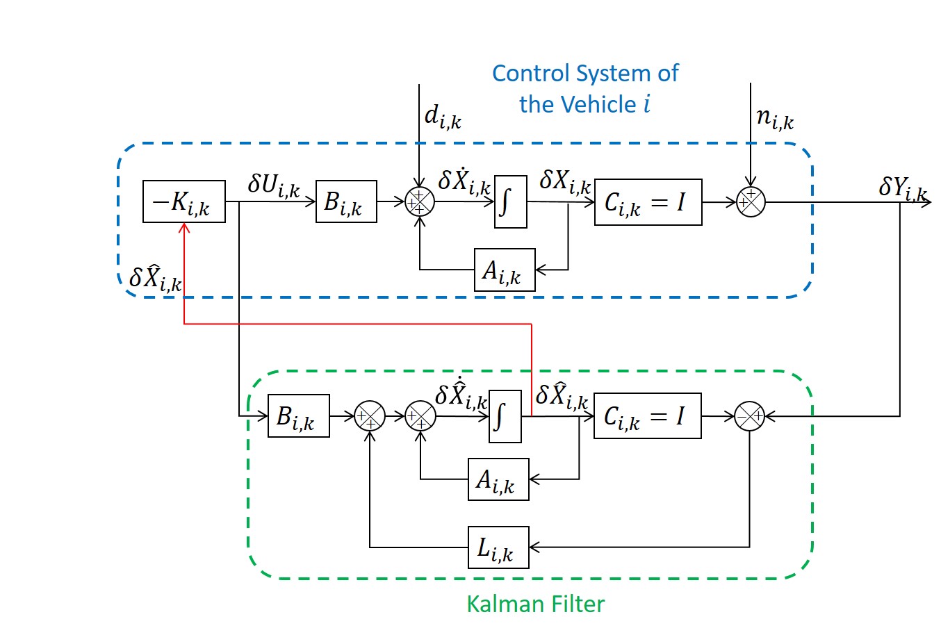
LQG Controller: As shown in Fig. 2, LQG design integrates a linear quadratic (LQ) controller and a Kalman estimator to the control system of the the quadcopter .
The Kalman filter dynamics
| (30) |
where
| (31) |
is called a Kalman gain and obtained from the Riccati equation bittanti2012riccati ,
| (32) |
Also, the control is chosen as
| (33) |
where
| (34) |
is obtained by solving algebraic Riccati equation:
| (35) |
Note that and where an denotes the expected value.
V Desired Trajectories of Quadcopters in a Continuum Deformation
Suppose every follower quadcopter () knows its own position and leaders’ positions at known sampling time and . Then, every follower quadcopter can set up its own desired trajectory without communication with other followers by applying the following steps:
- 1.
-
2.
Desired Trajectory Calculation: Set the desired trajectory of the follower at given leaders’ initial and final positions:
(36) .
Note that the desired velocity of the follower is constant:
| (37) |
VI Case Study: Cooperative Payload Delivery through a Narrow Channel
This section considers an MQS consisting of quadcopters, three leaders and seventeen followers. The MQS negotiates a narrow channel while it carries a payload. Leader and follower quadcopters all have the same properties as listed in Table 1 luukkonen2011modelling .
VI.1 Desired Continuum Deformation
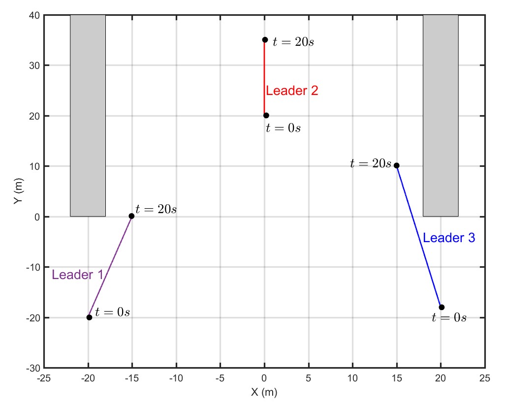
Leaders are located at , , and at . Leaders choose , , and as their desired positions at . The desired trajectories of the leaders are defined by
| (38) |
| (39) |
| (40) |
| Parameter | Value |
|---|---|
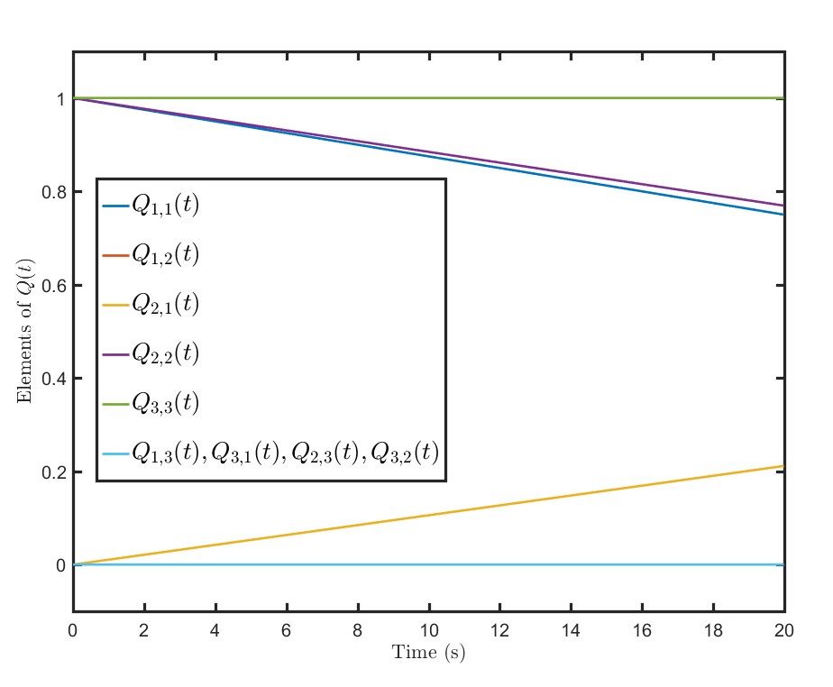
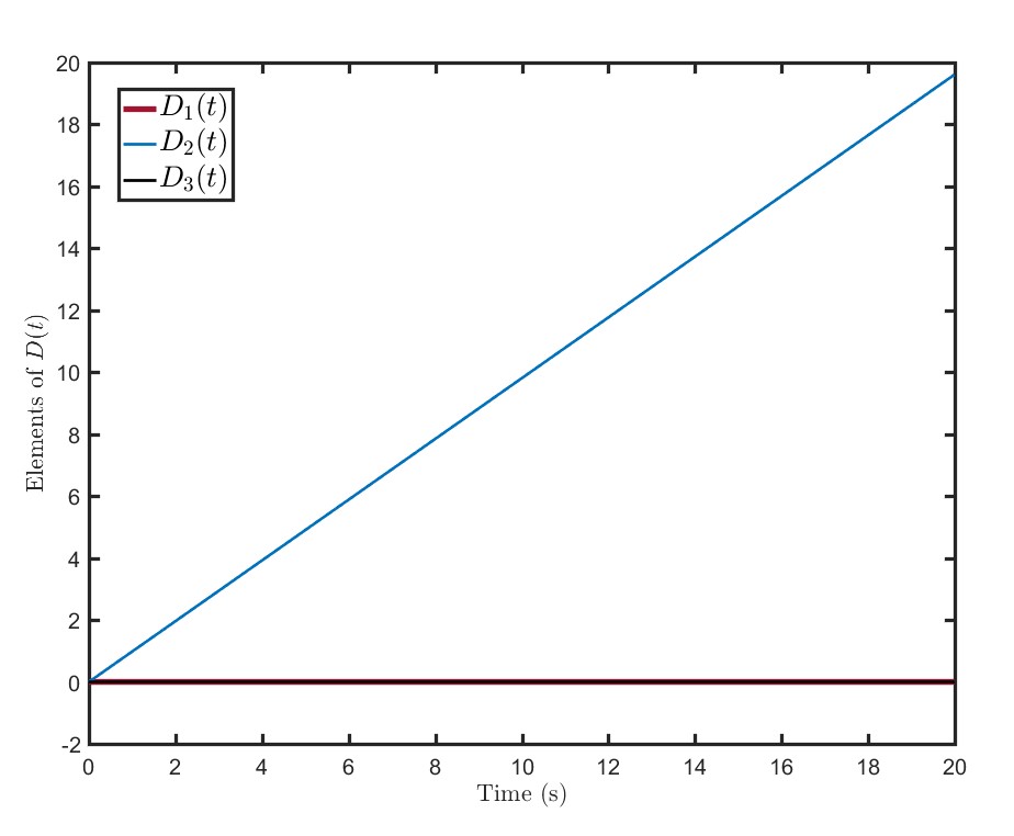
Fig. 3 (a) shows a top view of leaders’ paths in the plane . Given leaders’ positions at , elements of the Jacobian and rigid-body translation vector of the desired continuum deformation are obtained from Eq. (3) as depicted in Fig. 11 versus time. As shown, and () imply continuum deformation of the MQS in a plane normal to the axis. Additionally, and .
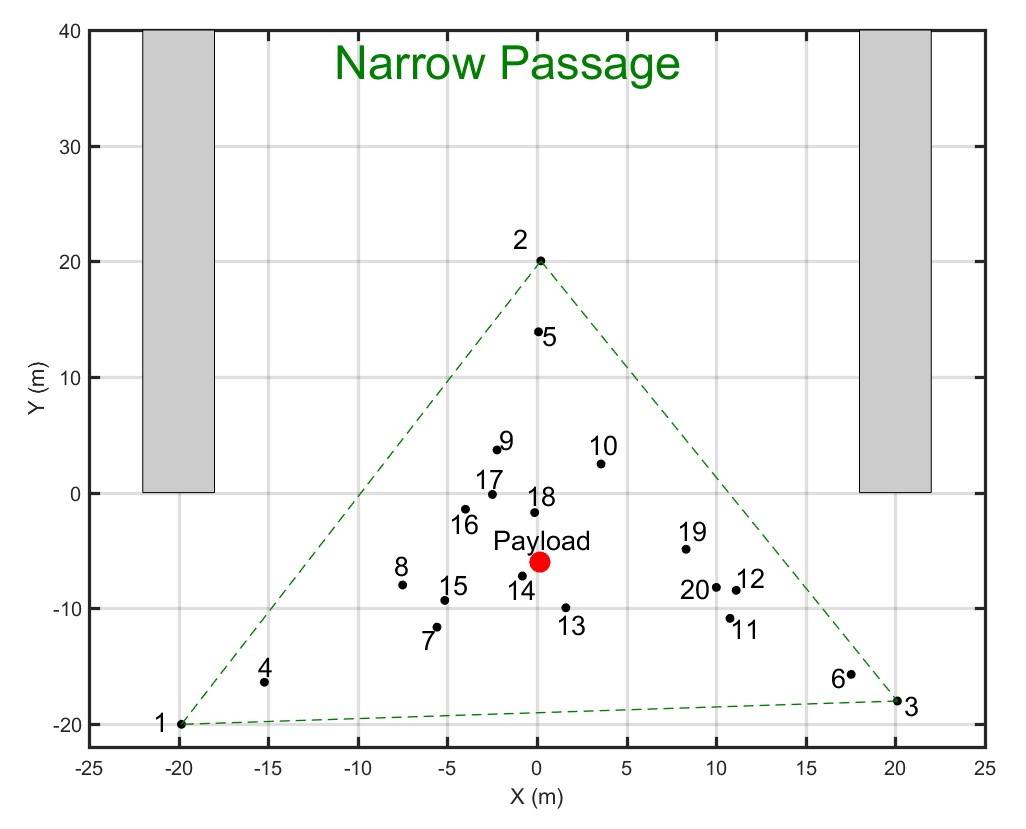
Each quadcopter learns the desired continuum deformation without communicating during . Each follower only needs to know the leaders’ initial and final positions as well as its own initial positions. Given initial position of follower as well as leaders’ initial positions (See Fig. 11 (b).), parameter () is assigned from Eq. (9). Parameters as well as quadcopter initial positions are listed in Table 2. Knowing parameters , , , as well as leaders’ initial and final desired positions, follower can assign its own desired trajectory according to Eq. (37).
| i | ||||||
|---|---|---|---|---|---|---|
| 1 | -20 | -20 | 50 | - | - | - |
| 2 | 0 | 20 | 50 | - | - | - |
| 3 | 20 | -18 | 50 | - | - | - |
| 4 | 18.5553 | -16.4474 | 50 | 0.8411 | 0.0838 | 0.0751 |
| 5 | 2.9446 | 14.0859 | 50 | 0.0774 | 0.8497 | 0.0730 |
| 6 | 18.7505 | -15.5800 | 50 | 0.0334 | 0.0625 | 0.9040 |
| 7 | 15.8793 | -11.5596 | 50 | 0.5457 | 0.1989 | 0.2554 |
| 8 | 14.2071 | -7.9219 | 50 | 0.5462 | 0.2937 | 0.1600 |
| 9 | 8.1559 | 3.7254 | 50 | 0.2730 | 0.5857 | 0.1413 |
| 10 | 9.0793 | 2.5421 | 50 | 0.1431 | 0.5475 | 0.3094 |
| 11 | 16.1245 | -10.9749 | 50 | 0.1365 | 0.1936 | 0.6699 |
| 12 | 14.7419 | -8.5407 | 50 | 0.0996 | 0.2578 | 0.6426 |
| 13 | 15.3257 | -9.5906 | 50 | 0.3499 | 0.2343 | 0.4158 |
| 14 | 13.8798 | -7.1498 | 50 | 0.3720 | 0.3052 | 0.3228 |
| 15 | 14.9875 | -9.0965 | 50 | 0.5025 | 0.2577 | 0.2398 |
| 16 | 10.9917 | -1.7927 | 50 | 0.3838 | 0.4547 | 0.1615 |
| 17 | 10.4800 | -0.2296 | 50 | 0.3252 | 0.4864 | 0.1884 |
| 18 | 10.9509 | -1.7695 | 50 | 0.2883 | 0.4425 | 0.2692 |
| 19 | 12.8728 | -4.8958 | 50 | 0.1183 | 0.3532 | 0.5285 |
| 20 | 14.5688 | -7.9380 | 50 | 0.1182 | 0.2682 | 0.6137 |
VI.2 Desired Quadcopter States
Dynamics of the Payload: By applying Newton’s second law the payload dynamics is given by
| (41) |
where is the total number of cables (quadcopters), is the payload mass, is the payload acceleration, and is the force in cable connecting the payload to quadcopter . It is assumed that cable acts as a spring, therefore,
| (42) |
where is the current length of cable , is the stiffness of cable , and is the free length of cable . Notice that the force in cable () is in the direction of the line segment connecting the payload to quadcopter .
Aerodynamic force exerted on the payload is given by
| (43) |
where is a zero-mean random vector with covariance matrix
Because leaders’ trajectories are linear with respect to time, follower quadcopter desired trajectories given by the homogeneous deformation are also linear with respect to time (see Eq. (8).). To specify the payload acceleration used in Eq. (IV.3.2), , , and in Eqs. (41) and (42) are substituted by
| (44) |
where , , and are obtained from Eq. (8) and is a zero-mean random vector with covariance
Desired Tension Force : To assign matrices and (see Eq. (IV.3.2)), one must determine tension force exerted on quadcopter . Given the th quadcopter position and payload position ,
| (45) |
assigns the direction of cable . By applying Newton’s second law, we can write
| (46) |
Note that is obtained from Eq. (41), therefore, the right hand side of Eq. (46) as well as the unit vector
| (47) |
are known. By writing Eq. (46) component wise, we obtain three equations with twenty unknowns . This is an over-determined problem that can be solved by modeling cables as parallel springs. We assume all cables have the same stiffness , thus,
| (48) |
where is the axial displacement of the cable . Payload is displaced in the direction of the vector . Define as the payload displacement,
| (49) |
is substituted in Eq. (50). Thus, Eq. (50) can be rewritten as follows:
| (50) |
Eq. (46) can be converted to the following with a dot product operation:
| (51) |
Eqs. (50) and (51) assigning can then be written as follows:
| (52) |
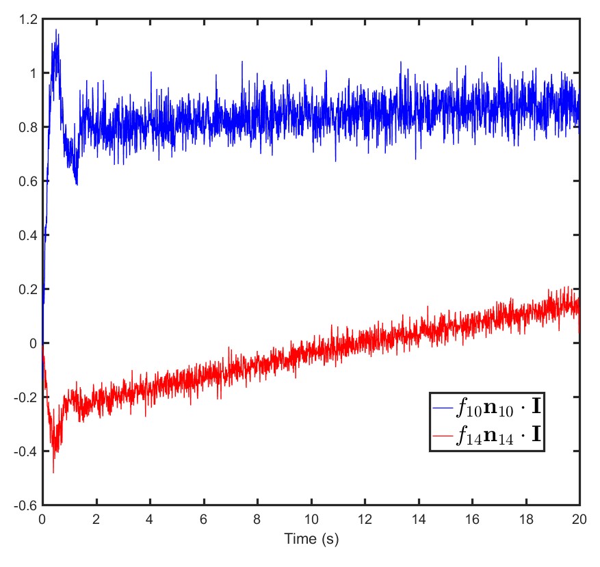
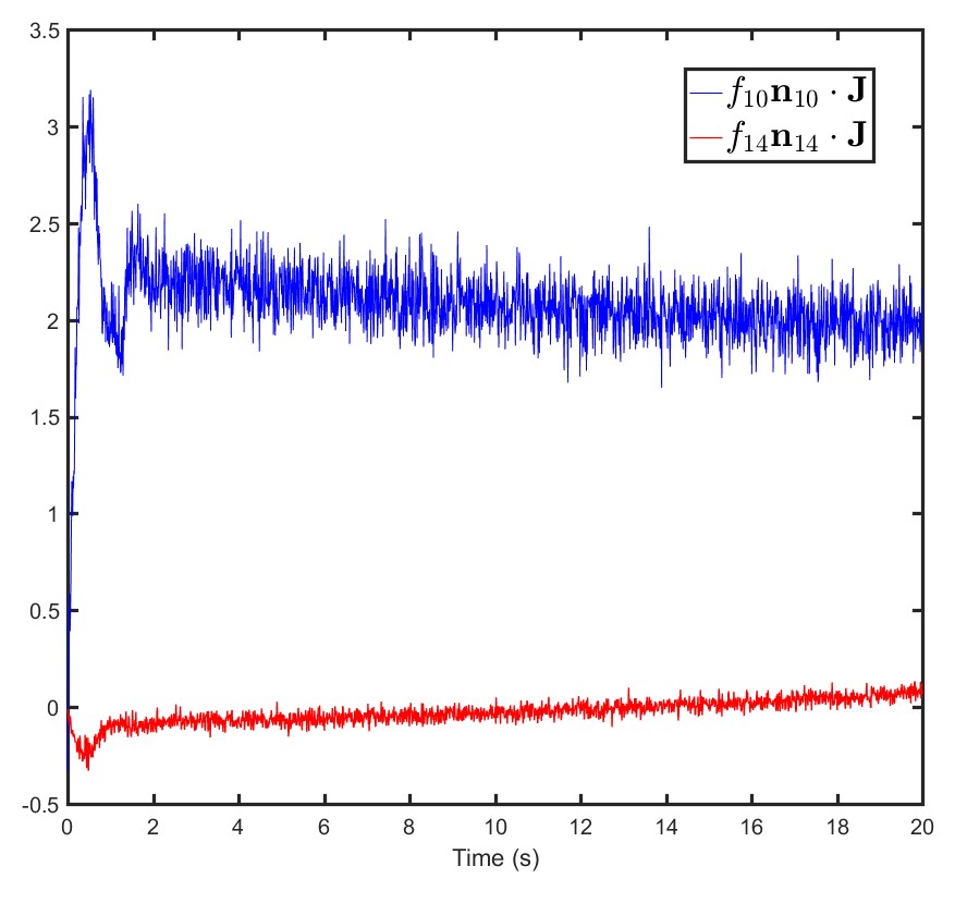
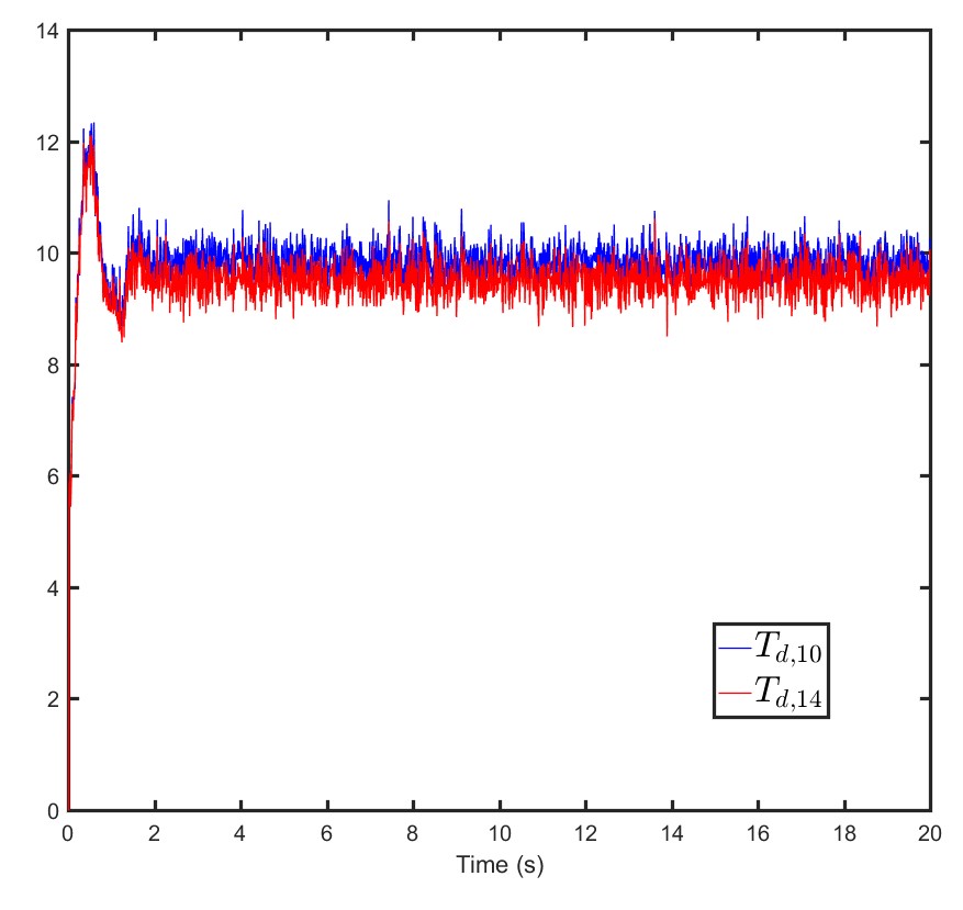
Payload motion simulation parameters are given in Table 3. In Fig. 5 components of the tension force in cables and are shown versus time.
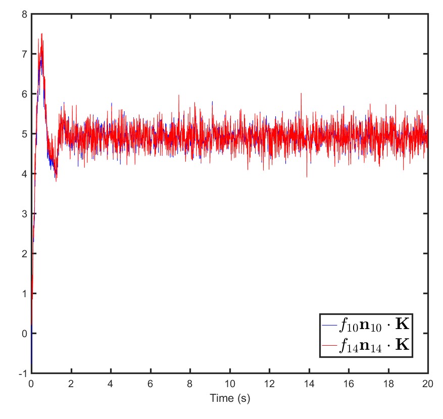
Desired Thrust : Desired thrusts of the quadcopters are computed by using Eq. (21). Fig. 6(a) depicts desired thrusts and versus time.
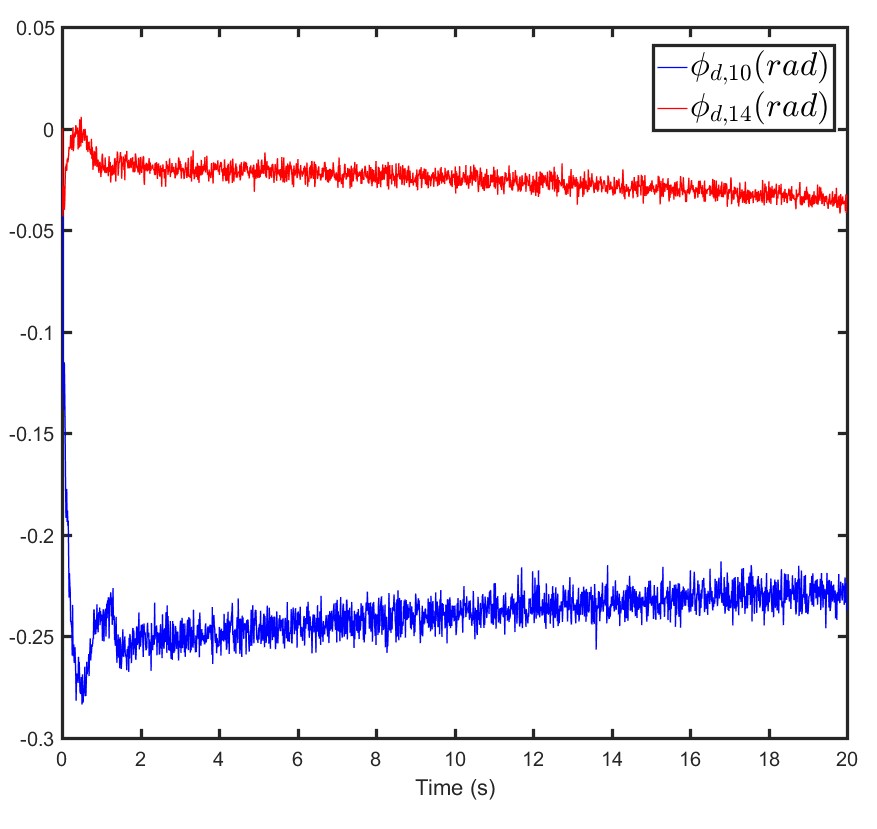
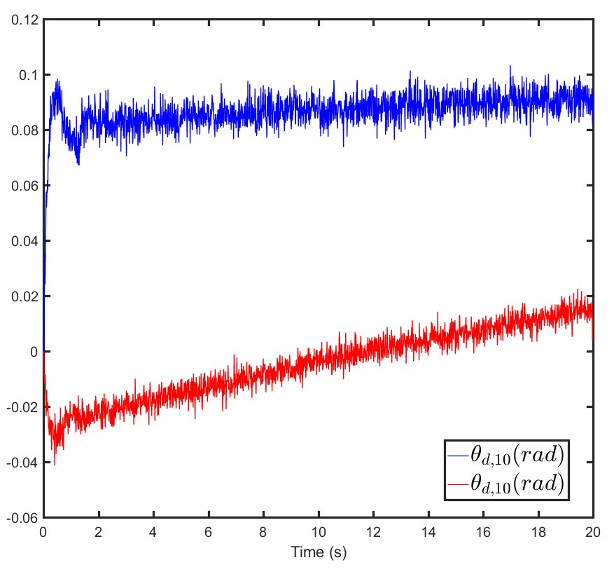
Desired Euler Angles : The desired path of quadcopter is a straight line, so (). Desired Euler angles of quadcopters and are calculated from Eq. (23) and shown versus time in Fig. 6(b) and (c).
| Parameter | Value |
|---|---|
VI.3 LQG Controller
Because desired velocities are constant, Euler angles and their derivatives are small, and dynamics of quadcopter can be approximated by linear time invariant (LTI) dynamics with and . Given the desired quadcopter states at , matrices and are computed from Eq. (27).
We consider , therefore, the initial state defined by Eq. (29) is updated at from
to simulate quadcopter collective motion.


VI.4 Results
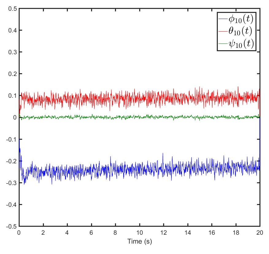
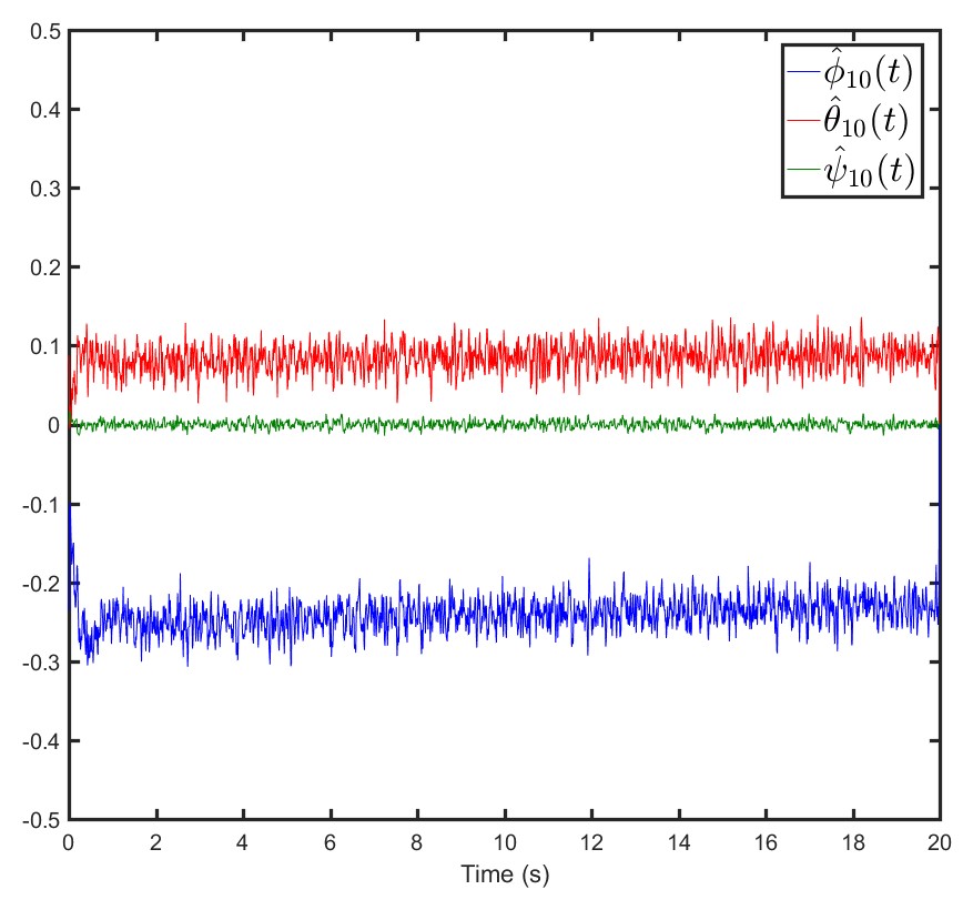
Fig. 7 shows , , and (components of actual position of the quadcopter ), , , and (Kalman filter estimation), and , , and versus time. Actual and estimated Euler angles of quadcopter are shown versus time in Fig. 8.
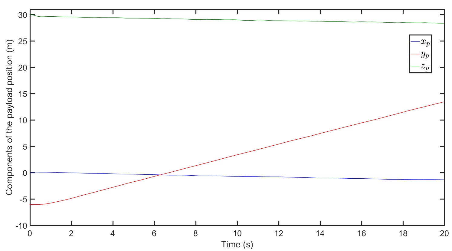

Fig. 9 shows payload position components (, , and ) versus time. Tensions in the connecting cables are also plotted versus time in Fig. 10. The MQS formation and the payload at different sample times are shown in Fig. 11.
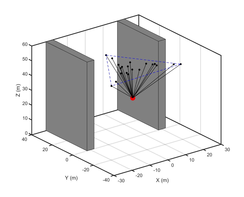
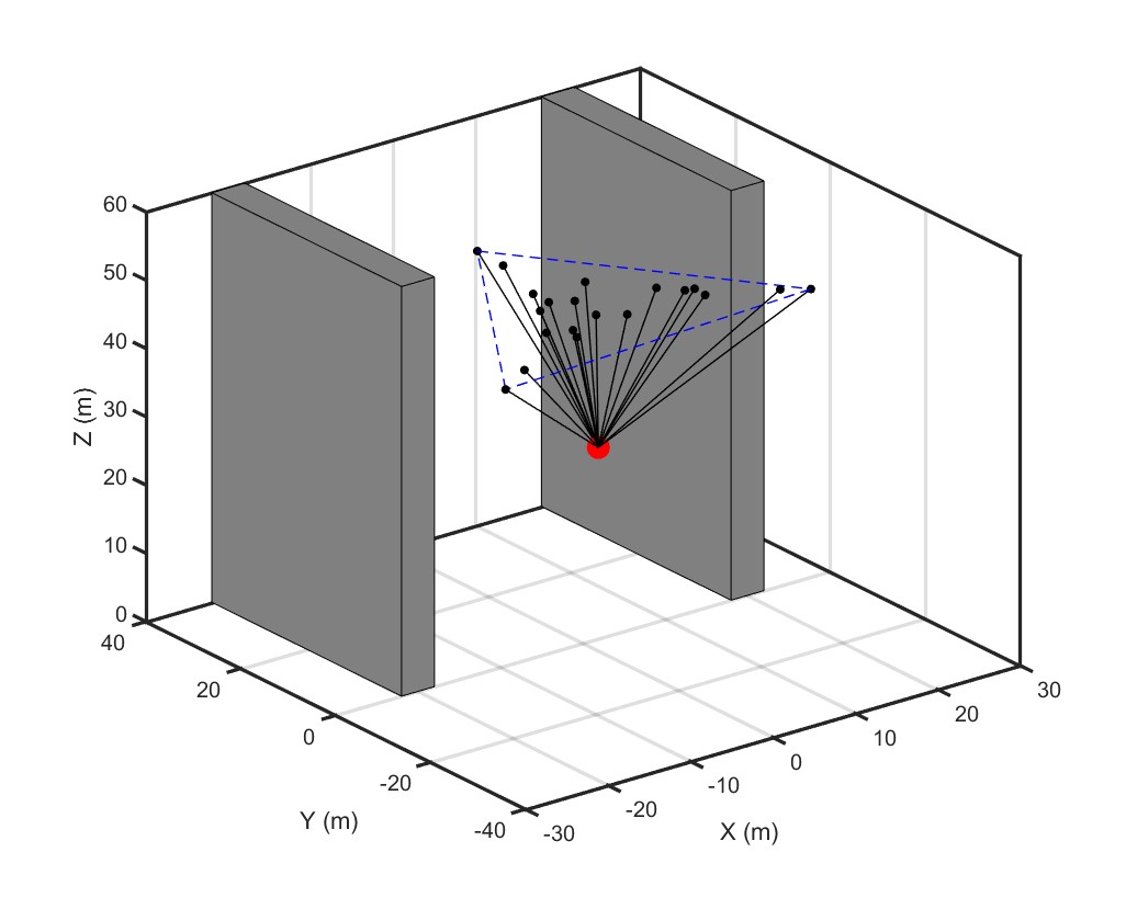
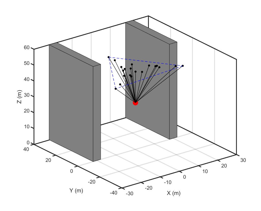
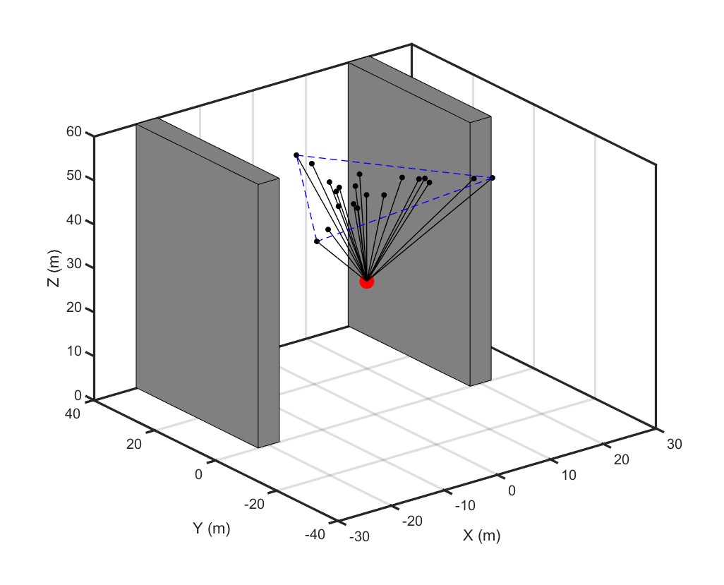

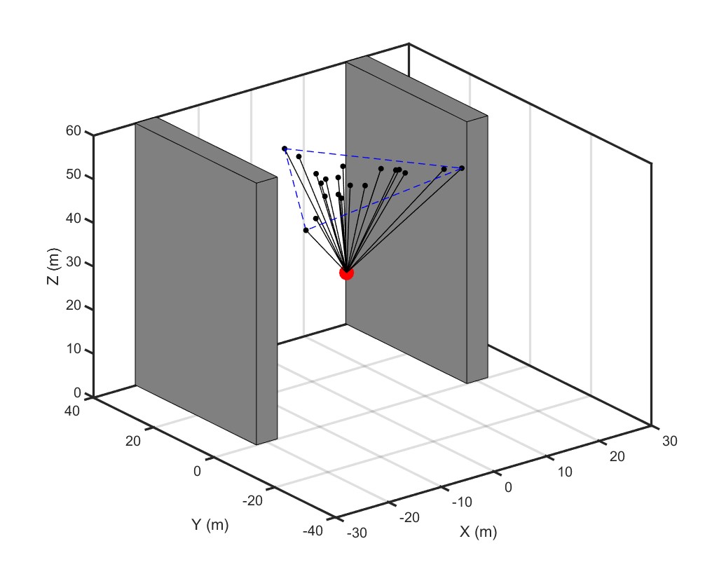
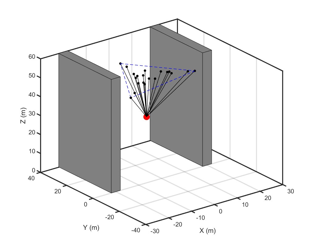
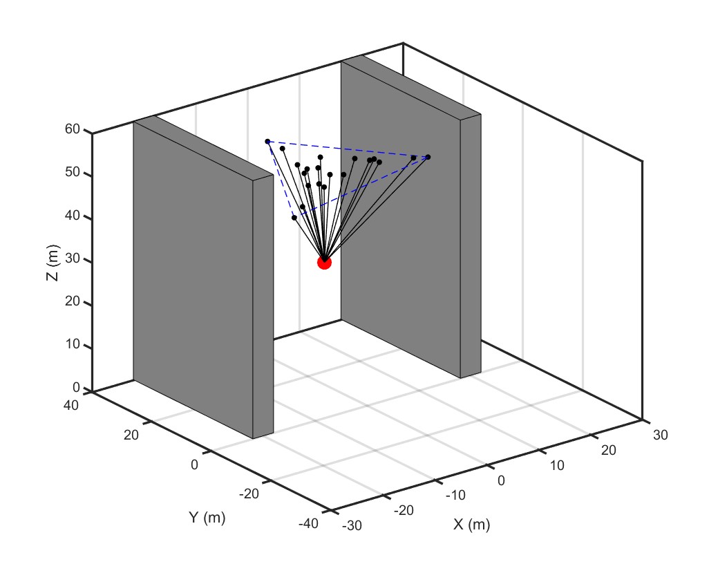
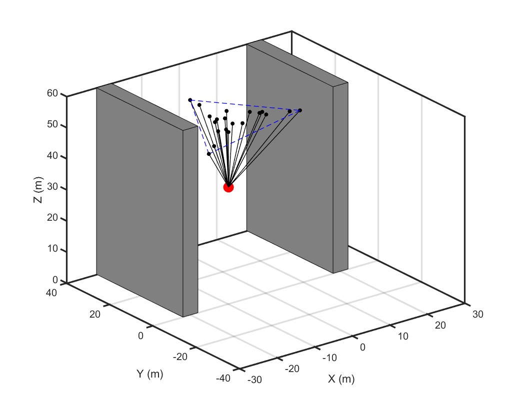
Fig. 7(b) shows that the Kalman filter of quadcopter successfully estimates the actual position of quadcopter 10. Fig. 7(c) shows that the controller is also able to accurately track the desired quadcopter trajectory. This situation is similar for all other quadcopters.
The covariance matrix is defined as
| (53) |
It is observed that eigenvalues of the symmetric matrix are all positive or zero. Additionally, deviation of the quadcopter from the desired position is characterized by
| (54) |
The simulation results show that
| (55) |
Expressing in its spectural decomposition form,
| (56) |
it is concluded that the variance of the greatest deviation from the desired position is pointed to the direction . Note that is along an axis that is almost parallel to the unit vector . Also, variances of the greatest deviation in the deformation plane are not large.
Furthermore, deviation of actual Euler angles () from the desired Euler angles () is obtained from
| (57) |
where
| (58) |
Notice that , , and , thus, deviations of the actual Euler angles from their desired values are negligible. Considering the results of Eigen-analysis, it is concluded that the LQG controller can be successfully applied in a payload delivery mission when the payload is carried by large number of UAVs.
VII Conclusion
The paper applies the recently-developed continuum deformation algorithm to an application in which multiple quadcopters carry a single parcel cooperatively. Path planning and motion control algorithms are proposed and validated in simulation. This paper described how a desired continuum deformation can be acquired by follower quadcopters only by knowing leaders’ positions at certain sample times without any further communication, minimizing communication costs. Because continuum deformation of an MQS is scalable, a large MQS team can cooperatively carry a heavy payload without the need for a heavy-lift quadcopter design. Because continuum deformation allows expansion and contraction of inter-agent distances, it also provides the ability for the team to pass through a narrow channel without collision as demonstrated in a twenty-quadcopter case study. The quadcopter LQG controller provides robust tracking of the desired trajectory assigned by continuum deformation despite disturbance inputs.
Acknowledgement
This work was supported in part under Office of Naval Research (ONR) grant N000141410596.
References
References
- (1) Proud, A. W., Pachter, M., and D’Azzo, J. J., “Close formation flight control,” in “Proceedings of the AIAA Guidance, Navigation and Control Conference,” , 1999, pp. 1231–1246.
- (2) Fax, J. A. and Murray, R. M., “Information flow and cooperative control of vehicle formations,” IEEE transactions on automatic control, Vol. 49, No. 9, 2004, pp. 1465–1476.
- (3) Paterno, F., Santoro, C., and Tahmassebi, S., “Formal models for cooperative tasks: concepts and an application for en-route air traffic control,” in “Design, Specification and Verification of Interactive Systems’ 98,” Springer, pp. 71–86, 1998.
- (4) Michael, N., Fink, J., and Kumar, V., “Cooperative manipulation and transportation with aerial robots,” Autonomous Robots, Vol. 30, No. 1, 2011, pp. 73–86.
- (5) Schmale Iii, D. G., Dingus, B. R., and Reinholtz, C., “Development and application of an autonomous unmanned aerial vehicle for precise aerobiological sampling above agricultural fields,” Journal of Field Robotics, Vol. 25, No. 3, 2008, pp. 133–147.
- (6) Michael, N., Kim, S., Fink, J., and Kumar, V., “Kinematics and statics of cooperative multi-robot aerial manipulation with cables,” in “ASME 2009 International Design Engineering Technical Conferences and Computers and Information in Engineering Conference,” American Society of Mechanical Engineers, 2009, pp. 83–91.
- (7) Bahceci, E., Soysal, O., and Sahin, E., “A review: Pattern formation and adaptation in multi-robot systems,” Robotics Institute, Carnegie Mellon University, Pittsburgh, PA, Tech. Rep. CMU-RI-TR-03-43.
- (8) Bazoula, A., Djouadi, M., and Maaref, H., “Formation control of multi-robots via fuzzy logic technique,” International Journal of Computers, Communications & Control, Vol. 3, No. 3.
- (9) Murray, R. M., “Recent research in cooperative control of multivehicle systems,” Journal of Dynamic Systems, Measurement, and Control, Vol. 129, No. 5, 2007, pp. 571–583.
- (10) Olfati-Saber, R., Fax, J. A., and Murray, R. M., “Consensus and cooperation in networked multi-agent systems,” Proceedings of the IEEE, Vol. 95, No. 1, 2007, pp. 215–233.
- (11) Ren, W., “Distributed leaderless consensus algorithms for networked Euler–Lagrange systems,” International Journal of Control, Vol. 82, No. 11, 2009, pp. 2137–2149.
- (12) Cao, Y., Stuart, D., Ren, W., and Meng, Z., “Distributed containment control for multiple autonomous vehicles with double-integrator dynamics: algorithms and experiments,” IEEE Transactions on Control Systems Technology, Vol. 19, No. 4, 2011, pp. 929–938.
- (13) Li, J., Ren, W., and Xu, S., “Distributed containment control with multiple dynamic leaders for double-integrator dynamics using only position measurements,” IEEE Transactions on Automatic Control, Vol. 57, No. 6, 2012, pp. 1553–1559.
- (14) Frihauf, P. and Krstic, M., “Leader-enabled deployment onto planar curves: A PDE-based approach,” IEEE Transactions on Automatic Control, Vol. 56, No. 8, 2011, pp. 1791–1806.
- (15) Bernard, M., Kondak, K., Maza, I., and Ollero, A., “Autonomous transportation and deployment with aerial robots for search and rescue missions,” Journal of Field Robotics, Vol. 28, No. 6, 2011, pp. 914–931.
- (16) Bernard, M., Kondak, K., and Hommel, G., “A slung load transportation system based on small size helicopters,” in “Autonomous Systems–Self-Organization, Management, and Control,” Springer, pp. 49–61, 2008.
- (17) Palunko, I., Fierro, R., and Cruz, P., “Trajectory generation for swing-free maneuvers of a quadrotor with suspended payload: A dynamic programming approach,” in “Robotics and Automation (ICRA), 2012 IEEE International Conference on,” IEEE, 2012, pp. 2691–2697.
- (18) Kim, S., Choi, S., and Kim, H. J., “Aerial manipulation using a quadrotor with a two dof robotic arm,” in “2013 IEEE/RSJ International Conference on Intelligent Robots and Systems,” IEEE, 2013, pp. 4990–4995.
- (19) Mellinger, D., Lindsey, Q., Shomin, M., and Kumar, V., “Design, modeling, estimation and control for aerial grasping and manipulation,” in “2011 IEEE/RSJ International Conference on Intelligent Robots and Systems,” IEEE, 2011, pp. 2668–2673.
- (20) Sreenath, K. and Kumar, V., “Dynamics, control and planning for cooperative manipulation of payloads suspended by cables from multiple quadrotor robots,” rn, Vol. 1, No. r2, 2013, p. r3.
- (21) Mellinger, D., Shomin, M., Michael, N., and Kumar, V., “Cooperative grasping and transport using multiple quadrotors,” in “Distributed autonomous robotic systems,” Springer, pp. 545–558, 2013.
- (22) Bisgaard, M., la Cour-Harbo, A., and Bendtsen, J. D., “Adaptive control system for autonomous helicopter slung load operations,” Control Engineering Practice, Vol. 18, No. 7, 2010, pp. 800–811.
- (23) Potter, J., Singhose, W., and Costelloy, M., “Reducing swing of model helicopter sling load using input shaping,” in “2011 9th IEEE International Conference on Control and Automation (ICCA),” IEEE, 2011, pp. 348–353.
- (24) Dai, S., Lee, T., and Bernstein, D. S., “Adaptive control of a quadrotor UAV transporting a cable-suspended load with unknown mass,” in “53rd IEEE Conference on Decision and Control,” IEEE, 2014, pp. 6149–6154.
- (25) Pounds, P. E., Bersak, D. R., and Dollar, A. M., “Grasping from the air: Hovering capture and load stability,” in “Robotics and Automation (ICRA), 2011 IEEE International Conference on,” IEEE, 2011, pp. 2491–2498.
- (26) Jiang, Q. and Kumar, V., “The inverse kinematics of cooperative transport with multiple aerial robots,” IEEE Transactions on Robotics, Vol. 29, No. 1, 2013, pp. 136–145.
- (27) Boyd, S. P. and Barratt, C. H., Linear controller design: limits of performance, Prentice Hall Englewood Cliffs, NJ, 1991.
- (28) Kalman, R. E., “A new approach to linear filtering and prediction problems,” Journal of basic Engineering, Vol. 82, No. 1, 1960, pp. 35–45.
- (29) Brown, R. G. and Hwang, P. Y., “Introduction to random signals and applied Kalman filtering: with MATLAB exercises and solutions,” Introduction to random signals and applied Kalman filtering: with MATLAB exercises and solutions, by Brown, Robert Grover.; Hwang, Patrick YC New York: Wiley, c1997., Vol. 1.
- (30) Rastgoftar, H., Continuum Deformation of Multi-Agent Systems, Birkhäuser, 2016.
- (31) Rastgoftar, H., Kwatny, H. G., and Atkins, E. M., “Asymptotic Tracking and Robustness of MAS Transitions Under a New Communication Topology,” .
- (32) Rastgoftar, H. and Atkins, E. M., “Continuum Deformation of Multi-Agent Systems Under Directed Communication Topologies,” Journal of Dynamic Systems, Measurement, and Control, Vol. 139, No. 1, 2017, p. 011002.
- (33) Lai, W. M., Rubin, D. H., Rubin, D., and Krempl, E., Introduction to continuum mechanics, Butterworth-Heinemann, 2009.
- (34) Bittanti, S., Laub, A. J., and Willems, J. C., The Riccati Equation, Springer Science & Business Media, 2012.
- (35) Luukkonen, T., “Modelling and control of quadcopter,” Independent research project in applied mathematics, Espoo.