Blood crystal: emergent order of red blood cells under wall-confined shear flow
Abstract
Driven or active suspensions can display fascinating collective behavior, where coherent motions or structures arise on a scale much larger than that of the constituent particles. Here, we report experiments and numerical simulations revealing that red blood cells (RBCs) assemble into regular patterns in a confined shear flow. The order is of pure hydrodynamic and inertialess origin, and emerges from a subtle interplay between (i) hydrodynamic repulsion by the bounding walls which drives deformable cells towards the channel mid-plane and (ii) intercellular hydrodynamic interactions which can be attractive or repulsive depending on cell-cell separation. Various crystal-like structures arise depending on RBC concentration and confinement. Hardened RBCs in experiments and rigid particles in simulations remain disordered under the same conditions where deformable RBCs form regular patterns, highlighting the intimate link between particle deformability and the emergence of order. The difference in structuring ability of healthy (deformable) and diseased (stiff) RBCs creates a flow signature potentially exploitable for diagnosis of blood pathologies.
pacs:
47.57.E-, 47.57.Qk, 87.16.D-, 87.19.U-Introduction.—
Blood is a dense suspension of red blood cells (RBCs) of about 45% volume fraction. Blood microstructure (RBC shapes and spatio-temporal distribution) strongly depends on flow conditions (local shear, flow curvature, vessel-cell size ratio) Popel and Johnson (2005); Suresh (2006); Abkarian et al. (2008); Abkarian and Viallat (2008); Vlahovska et al. (2009a); Fedosov et al. (2011); Li et al. (2012); Dupire et al. (2012). For example, in capillary flows the RBC can adopt variety of morphologies, distinctly different than its biconcave equilibrium shape Lanotte et al. (2016). Parachute-shaped RBCs can arrange in a single file of regularly spaced cells McWhirter et al. (2009a, 2012); Tomaiuolo et al. (2012), a pattern also observed with droplets in microfluidic inertialess flows Beatus et al. (2006, 2007, 2012); Uspal and Doyle (2012); Janssen et al. (2012); Shani et al. (2014a); Uspal and Doyle (2014). Confinement is one factor promoting the order in these systems. If the bounding walls are removed then the particles can pass over each other and experience hydrodynamical diffusion (a cross-flow displacement after collision) da Cunha and Hinch (1996); Zhao et al. (2012); Grandchamp et al. (2013); Henríquez Rivera et al. (2015) that, very much like classical diffusion, favors homogenization (intermixing of suspended entities) and tends to destroy any order. Another factor that gives rise to complex collective dynamics and order is the long-range hydrodynamic interactions between the fluid-embedded particles. These interactions, i.e., correlations in the motions of particles mediated by flows in the suspending liquid, underly many self-organizing phenomena, from the microfluidic crystals Beatus et al. (2007); Baron et al. (2008); Lee et al. (2010); Humphry et al. (2010); Shani et al. (2014b) to directed macroscopic motion in self-rotating particles Bricard et al. (2013, 2015); Yeo et al. (2015); Goto and Tanaka (2015).
Unlike for pressure-driven flows, structuring of RBCs (or drops and capsules) under confined shear flows has not been studied even though there are experiments showing formation of trains in RBC suspensions Fischer and Richardson (1980); Bull et al. (1983) and emulsions Pathak et al. (2002). To fill this void, we carried out experiments and 3D numerical simulations to study the formation of two-dimensional arrays (crystals) by RBCs sheared between two parallel plates. We observe ordering of RBCs. Intriguingly the order persists even when the size of the gap allows cells to pass over each other, i.e., the emergence of order does not require strong confinement. We develop an analytical model that provides a physical insight into the phenomena. The pattern wavelength (cell-cell separation) predicted by the model is in excellent agreement with simulations and experiments.
The model.—
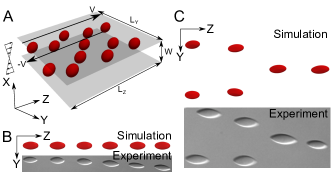
The lattice Boltzmann method (LBM) Krüger et al. (2013, 2014) was used to solve the quasi-incompressible Navier-Stokes equations for fluid flow. The membrane energy consists of a contribution due to resistance to bending , with the mean curvature and the bending rigidity modulus, and resistance to in-plane shearing and stretching , where is the shear elastic modulus, is the area dilation modulus, and and are the in-plane strain invariants (see Krüger et al. (2013)). is chosen large enough to preserve local area conservation. The RBC size is taken to be m. The reduced volume is defined as , with the particle surface area and its volume. was used for RBC model when compared with experiments, otherwise was used (in this case we refer to the cell as a capsule model). This allowed computational efficiency without affecting the main results (see below). is the capillary number. is set to 0.05. The viscosity contrast is fixed to one. The reference shape is taken to be to the equilibrium one in the absence of shear elasticity. The suspension is sheared between two parallel planes at a constant shear rate , where is the relative velocity of the planes and the channel width (Fig. 1A).
The experimental set-up.—
The experiments were performed in a home-made rheoscope with cone-plate geometry. Microscopic images were taken with a CCD camera (DMK 41BF02.H, The Imaging Source Europe GmbH, Bremen, Germany). Normal blood samples were obtained from the EFS (Etablissement Français du Sang) and kept refrigerated until use. Solid spherical particles were produced by suspending RBCs in an isotonic solution of sodium salicylate (Sigma-Aldrich) thus converting the biconcave RBCs into spheroechinocytes. This shape was then conserved by fixation with 0.25% glutaraldehyde (Alfa Aesar, Karlsruhe, Germany). RBCs and rigid spheres were washed three times with isotonic PBS (Dulbecco, biowest, Nuaille, France). RBCs or spheres were suspended in an isotonic solution of dextran (MW 500000 D, Sigma-Aldrich, Saint-Quentin Fallavier, France) plus PBS. The viscosity at room temperature (25∘C) was 50mPas (Anton Paar, Rheoplus, Graz, Austria), and for some experiments (as shown in SM ), unless otherwise indicated. Suspensions of RBCs or spheres were prepared with volume fractions between 0.002 and 0.01 and were loaded into the cone-plate chamber. The shear rate was varied from 15 to 94 . The viscosity of the hemoglobin solution of healthy RBCs is around 10 mPa.s at room temperature (25∘C). The experimental capillary number is in the range .
Flow-aligned chains.
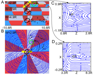
— RBCs in shear flow display two main types of dynamics depending on the applied shear stress: Tank-treading (TT) at large shear stress, where the cell assumes stable orientation relative to applied shear direction, and tumbling at low enough shear stress, where the cell executes periodic flipping motion Fischer et al. (1978). In both simulations and experiments the parameters are chosen such that cells are in the TT regime. Experiments and simulations show the formation of regularly spaced chains of RBCs aligned with the flow direction, see Fig. 1B and Movie 1 and 2 in SM .
Starting from a random initial cell distribution, we observe a transient regime during which cells mix (hydrodynamical diffusion) due to cell-cell hydrodynamic interactions and migrate towards the midplane due to the hydrodynamic repulsion by the wall. Once all cells have reached the channel midplane, the degree of disorder decreases continuously until the cells reach an ultimate stable configuration of ordered chains (Fig. 1B). Both experiments and simulations show that chains can merge into a stable Y-configuration (Fig. 1C).
The finite ratio between channel width and cell size is a crucial factor in the cell structuring. We find that stable order is impossible if the cells were considered as points. An intriguing observation (analyzed in detail below) is that order persists even for weakly confined suspensions (with the gap between planes about ten times the cell radius ), where one would have expected that cell-cell hydrodynamic interactions (responsible for hydrodynamic diffusion) pushing the cells out of the channel center would allow the imposed shear flow to advect the cells further apart, thereby favoring disorder.
Crystals.—
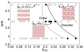
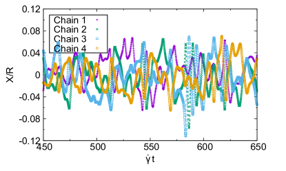
Numerical simulations show that at low particle volume fraction, capsules form flow-aligned chains. The spacing between the chains in the vorticity direction also shows periodicity. The chains slide relative to each other due to a slight displacement in (velocity gradient)-direction and advection by the imposed shear flow (see Movie 3 in SM ). Interestingly, the chain offset along fluctuates in time but despite these fluctuations the order in the (flow) direction persists (see also Fig. 1 in SM ). The chaining occurs when starting from a random RBC/capsule distribution in 3D. Two closely located parallel chains repel each other but still preserve their structure (see Movie 4 in SM ). Increasing the volume fraction results in formation of infinite 2D lattices. The crystal configuration assembles from random initial conditions (Movie 5 in SM ). At high volume fraction disorder prevails. Fig. 2 summarizes the phase behavior of the 2D crystals.
In addition to linear chains we discovered numerically other configurations. We explored the stability of other possible configurations of three, four and five capsules, as shown in Fig. 3, in order to probe the existence of crystalline structures other than 1D chains.
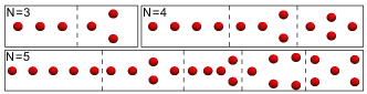
The simulations show that the final stable configurations are all symmetric about the flow direction. These elementary crystal configurations serve as building blocks to larger crystals and imply the existence of two types of crystals (a) a 1D crystal corresponding to an infinite chain and (b) a 2D crystal based on the triangular arrangements in Fig. 3. This triangular arrangement is also observed in experiments (Fig. 1C and Fig. 1 in SM for the whole image).
Effect of cell deformability.—
An important ingredient for the emergence of order to be discussed below is the wall-induced migration which requires cell deformation Cantat and Misbah (1999); Seifert (1999); Sukumaran and Seifert (2001). For a spherical particle, there is no cross-streamline migration in the Stokes regime, owing to the linearity of the Stokes equations. We analyzed the impact of cell deformability on the emergence of order (Fig.4). Our simulations show that rigid particles never settle in the midplane (due to the absence of wall-induced migration), and disorder prevails; solid spheres even if initially placed on the midplane, drift apart. This is illustrated by the simulation in Fig.4 where disordered pattern is obtained. Moreover, Fig. 4B shows that the distance between two given rigid particles increases with time without saturation (solid line), whereas the same quantity shows saturation (indicating stable pairing) when deformable cells are considered (dashed line).
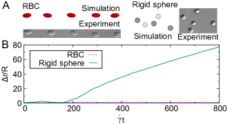
Experiments on hardened RBCs also confirm the lack of order (Fig.4 A). These results support the idea that the wall-induced migration due to particle deformability plays a crucial role in the ordering process. Note that in the presence of inertia, even a spherical particle will undergo a wall-induced migration allowing ordered patterns of rigid particles to be stabilizedHumphry et al. (2010). Inertia is also responsible for hydrodynamic ordering of rotating disks Goto and Tanaka (2015) and strong focalization of capsule suspensions Krüger et al. (2014) in a pressure-driven flow. Inertia, however, is negligible in our study.
Flow structure around a single cell and around a pair.—
Let us now focus on the basic understanding of the crystal formation. We first analyze the flow field around a single cell. Fig. 5B shows that in the Y-Z-plane this flow field is quadrupolar in nature. Fig. 5A shows the same flow in the -(shear)-plane. Fig. 5D zooms into the flow and shows the existence of recirculation zones, nonexistent in unconfined shear flow Zurita-Gotor et al. (2007); McWhirter et al. (2009b); Janssen et al. (2012). Their centers are designated as elliptic points (EPs) hereafter. The center of a TT cell also constitutes an EP. Between two EPs there is a point where the flow locally is hyperbolic (Fig. 5C). This point is referred to as hyperbolic point (HP). In Fig. 5A, these points are located where four colors meet. Movie 6 in SM illustrates experimentally the existence of an HP close to a single TT RBC. The EPs are essential for the formation of RBC chains as suggested earlier Fischer and Richardson (1980).
Fig.6 shows an example of the trajectory of pairing cells (B inset) and the flow field after a stable pair is formed (A left panel, see also Movie 7 in SM ). Comparison with Fig. 5A shows (i) that in pair formation the second cell settles close to the EPs created by the first cell (see also analytical theory below) and (ii) that between a cell pair there are two HPs and one EP.
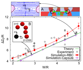
If pair formation is studied at different confinements an almost linear dependence of the equilibrium pair-distance with channel width is observed, Fig. 6. The experimental data is in good agreement with RBC simulations, and slightly above the capsule simulations and theory (see below). This indicates that the small reduced volume of RBCs causing their elongation also contributes to the equilibrium distance.
Analytical theory for pair formation.—
Here we provide a theoretical explanation for the pair formation. A detailed analysis of this phenomenon (see theory in SM ) shows that the pairing results from an intricate interplay between (i) a long-range hydrodynamic attraction of two cells along the flow direction, (ii) the wall-induced migration across the streamlines, (iii) a short range hydrodynamic repulsion between the cells due to the imposed shear flow (since the cell mass centers are not exactly on the midplane, their relative translational velocity is nonzero; thus the shear flow is acting to separate the pair). As dictated by translational invariance along , the coordinates of the cells in the pair can be written as and The question amounts to determining the steady state and stable positions and .
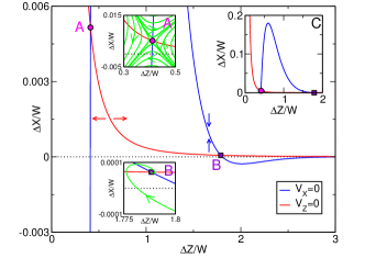
A steady-state solution corresponds to the velocity of both cells being zero (the pair of cells is at rest in the laboratory frame). The (flow-direction)-component of the velocity of a cell in a pair has two contributions: (i) the velocity field induced by the first cell and (ii) the unperturbed shear flow. The first effect can be well approximated by the quadrupolar flow field shown in Fig. 5B. This flow field has a monotonic algebraic decay (see SM ) as the distance between the two cells increases. The red curve in Fig. 7 shows the location where the total (quadrupolar + imposed shear) contribution to the -component of the velocity vanishes in the (, ) plane.
The (velocity-gradient direction)-component of the velocity of a cell in the pair has two contributions: (i) the flow induced by the other cell and (ii) the wall-induced migration across the streamlines. The first contribution has a complicated form Liron and Mochon (1976), which can be well approximated by a rapidly decaying attenuated sine wave (Theory in SM ). The second contribution is proportional to the cell displacement from the midplane (Theory in SM ). Equating the sum of these contributions to zero gives a second relation between and shown by the blue curve in Fig. 7.
The intersections of the blue and the red curves in Fig. 7 correspond to stationary separations of the two cells. Two such intersections can be identified: The separation corresponding to the point in Fig. 7 is unstable, as suggested by the orbits in Fig. 7A. The separation corresponding to the point is stable as suggested by the orbit in Fig. 7B.
For weak confinement (channel gap large compared to the cell size), we deduce an asymptotic scaling law (see SM )
| (1) |
This scaling is universal as it is independent of the details of the cell structural parameters. Details of the physical nature of the cell (e.g. reduced volume, elastic properties, etc..), or its precise shape shows up only in the correction terms SM to the main scaling given above. Equation (1) provides a very good agreement with the full numerical simulation (Fig.6).
We have analyzed the linear stability of the stationary-pair solution and found one real negative eigenvalue (by looking for perturbations in the form , with the eigenvalue), corresponding to the attraction along the direction and two complex eigenvalues with negative real parts corresponding to the stability in the --plane, shown schematically in Fig. 7B. The complex nature of the eigenvalues leads to spiraling of the trajectory towards to the stable fixed point (Fig. 7B).
Conclusions and outlook.—
We have studied the structures formed by RBC and capsule suspensions in weakly confined shear flow using experiments and numerical simulations with LBM. Most of the presented simulations are performed for quasi-spherical capsules (for numerical efficiency). However, we have checked that the main features are captured for a reduced volume equal to that of a RBC (see Movies 2 and 3 in SM ). Our work highlights the key roles of cell deformability and shape in the emergence of order. The analytical theory points to cross-stream migration of the cells as the driving force of cell-cell pairing and eventual multi-cell ordering. Our study suggests that the structures formed by RBCs with different pathologies could be different; this could serve as a diagnostic tool since several blood diseases are accompanied by decreased deformability (sickle cell anemia) or shape change (elliptocytosis). To explore this idea, more detailed, pathology-specific models of the RBC would be needed for the simulations. Cell-cell separation in a stable pair is found to be linearly dependent on the gap width and, for nearly spherical capsules, insensitive to the interfacial mechanics. This suggests that this result should apply to any other system of soft particles experiencing a wall-induced migration, such as drops and vesicles.
I Supplementary Material
Here we show that particle positions fluctuate (FIG. 8), yet the crystal is stable (See Movie 2) in simulations.
In experiment, stable Y-bifurcations form (FIG. 9).
I.1 Theory
We start with an analytical model of the quadrupolar flow field of a single cell. Along the flow direction, this field provides an attractive tendency for a second cell. To explain the establishment of an equilibrium distance of the two cells, we invoke two additional mechanisms: (i) the displacement of the second cell from the midplane due to the short-range flow disturbance by the first cell and (ii) the wall-induced migration due to the finite size of both cells.
Consider a single cell in a shear flow placed in the midplane at . The cell has a fixed orientation, while its membrane undergoes a TT motion. Shear flow contains a straining component that stretches the cell (see Vlahovska et al. (2009b)). The cell reacts by opposing this stretching (Fig. 6 of the main text, yellow arrows). This effect is characterized by a stresslet, which is a rank-2 tensor. For analytical simplicity we represent it by a force dipole . As will be seen later, this difference results only in different numerical prefactors of order unity, which do not affect the final answer.
From dimensional analysis (see Pozrikidis (1992)), the value of is defined by the geometry of the cell and the shear stress of the applied flow: Here is the viscosity of the suspending fluid. Far from the cell, the flow in the midplane has the structure of a 2D potential flow (Hele-Shaw flow) Liron and Mochon (1976). Hence, a force would create a flow equivalent to a 2D source dipole. Due to the superposition principle, a force dipole creates a flow corresponding to a 2D source quadrupole, described by:
| (2) |
where is the flow velocity, and are the respective unit vectors and superscript stands for quadrupolar. For this equation well approximates the flow field of the numerical calculations in the --plane (Fig. 2B of the main text). As shown in Fig. 2B of the main text, the second cell is attracted to a position . To assess the establishment of the equilibrium in and directions, we use Eq. 2 assuming .
The velocity of a second cell placed at reads Because is negative, this equation explains cell attraction, but a short-range repulsive interaction is also needed for a stable configuration to exist. The answer arises from a subtle combination of the hydrodynamic interaction (i) of the cell at positive with the cell at the origin and (ii) of both cells with the confining walls.
If well separated, cells stay in the midplane. However, as they approach each other due to the quadrupolar flow field, they are slightly pushed out of the midplane by short-range hydrodynamic interactions. By the symmetry of the problem, the displacement of the two cells from the midplane should be opposite. We therefore assume the first cell to be located at position and the second cell to be located at position For the -component of the velocity of the second cell has a contribution from the undisturbed shear flow For this second contribution can balance the first one, as is shown below.
The component of the cell velocity has two contributions: (i) hydrodynamic interaction with the other cell and (ii) wall-induced migration. Hydrodynamic interactions of particles in a fluid domain bounded by two parallel walls have been treated theoretically Liron and Mochon (1976). From the complicated formulae, we extracted the leading effect along the direction in a simple exploitable form. Our calculations show that the -component of the velocity induced by the first cell at the position of the second cell reads for
| (3) |
where superscript stands for short-range, , and vanishes at an infinite sequence of values of The velocity of the wall-induced migration scales as Farutin and Misbah (2013), where the superscript stands for lift.
An equilibrium state will be attained when both the and components of the test cell velocity are zero: and The former equation is represented by the red curve in Fig. 4 of the main text, while the latter corresponds to the blue curve. Solving this system yields and where and are numerical prefactors of order 1. A simple manipulation of these two equations yields the following final result
| (4) |
where is another numerical prefactor, and we have used the scaling In Fig. 4 of the main text, the two solutions of this equation are represented by a magenta circle and a purple square. For a large enough width (as compared to ) the left hand side becomes small compared to 1, so that the solutions of equation 4 are well approximated by zeros of the cosine function. This reasoning gives the scaling
| (5) |
for the stable intercellular distance, independent of details (for example there is no need to specify the values of the prefactors and ). The scaling (5) defines the position of the point in Fig. 4 of the main text. The point in Fig. 4 of the main text, corresponding to scaling proves to define an unstable stationary separation, as shown in Fig. 4A of the main text. During approach, the second cell essentially follows the red curve until finally spiraling into point as shown in Fig. 4B of the main text.
Reporting (4) into the -component of the equilibrium condition, yields where is a positive numerical prefactor. The sign is such that the cell with is slightly above the midplane, while the one with is slightly below. This result is in agreement with the full numerical simulation.
Acknowledgements.
We are very grateful to V. Marchenko for many stimulating discussions. We thank Q. Xie, M. Wouters and D. Hessling for the help in numerics. C.M., A.F. and Z.S. thank the CNES (Centre National d’Etudes Spatiales) for a partial financial support and the French-German University Programme ”Living Fluids” (Grant CFDA-Q1-14). T.F. thanks the LIPhy laboratory, where the experimental work was performed, for financial support. The CPU time was provided by the HLRS (High-Performance Computing Center Stuttgart).References
- Popel and Johnson (2005) A. S. Popel and P. C. Johnson, Annu Rev Fluid Mech 37, 43 (2005).
- Suresh (2006) S. Suresh, J Mater Res 21, 1871 (2006).
- Abkarian et al. (2008) M. Abkarian, M. Faivre, R. Horton, K. Smistrup, C. A. Best-Popescu, and H. A. Stone, Biomed Mater 3, 034011 (2008).
- Abkarian and Viallat (2008) M. Abkarian and A. Viallat, Soft Matter 4, 653 (2008).
- Vlahovska et al. (2009a) P. M. Vlahovska, T. Podgorski, and C. Misbah, C R Physique 10, 775 (2009a).
- Fedosov et al. (2011) D. A. Fedosov, W. X. Pan, B. Caswell, G. Gompper, and G. E. Karniadakis, Proc Nat Acad Sci 108, 11772 (2011).
- Li et al. (2012) X. Li, P. M. Vlahovska, and G. E. Karniadakis, Soft Matter 9, 28 (2012).
- Dupire et al. (2012) J. Dupire, M. Socol, and A. Viallat, Proc Nat Acad Sci 109, 20808 (2012).
- Lanotte et al. (2016) L. Lanotte, J. Mauer, S. Mendez, D. A. Fedosov, J.-M. Fromental, V. Claveria, F. Nicoud, G. Gompper, and M. Abkarian, Proc Nat Acad Sci 113, 13289 (2016).
- McWhirter et al. (2009a) J. L. McWhirter, H. Noguchi, and G. Gompper, Proc Nat Acad Sci 106, 6039 (2009a).
- McWhirter et al. (2012) J. L. McWhirter, H. Noguchi, and G. Gompper, New J Phys 14, 085026 (2012).
- Tomaiuolo et al. (2012) G. Tomaiuolo, L. Lanotte, G. Ghigliotti, C. Misbah, and S. Guido, Phys Fluids 24, 051903 (2012).
- Beatus et al. (2006) T. Beatus, T. Tlusty, and R. Bar-Ziv, Nat Phys 2, 743 (2006).
- Beatus et al. (2007) T. Beatus, R. Bar-Ziv, and T. Tlusty, Phys Rev Lett 99, 124502 (2007).
- Beatus et al. (2012) T. Beatus, R. H. Bar-Ziv, and T. Tlusty, Phys Rep 516, 103 (2012).
- Uspal and Doyle (2012) W. E. Uspal and P. S. Doyle, Soft Matter 8, 10676 (2012).
- Janssen et al. (2012) P. Janssen, M. Baron, P. Anderson, J. Blawzdziewicz, M. Loewenberg, and E. Wajnryb, Soft Matter 8, 7495 (2012).
- Shani et al. (2014a) I. Shani, T. Beatus, R. H. Bar-Ziv, and T. Tlusty, Nat Phys 10, 140 (2014a).
- Uspal and Doyle (2014) W. E. Uspal and P. S. Doyle, Soft matter 10, 5177 (2014).
- da Cunha and Hinch (1996) F. da Cunha and E. Hinch, J Fluid Mech 309, 211 (1996).
- Zhao et al. (2012) H. Zhao, E. S. Shaqfeh, and V. Narsimhan, Phys Fluids 24, 011902 (2012).
- Grandchamp et al. (2013) X. Grandchamp, G. Coupier, A. Srivastav, C. Minetti, and T. Podgorski, Phys Rev Lett 110, 108101 (2013).
- Henríquez Rivera et al. (2015) R. G. Henríquez Rivera, K. Sinha, and M. D. Graham, Phys Rev Lett 114, 188101 (2015).
- Baron et al. (2008) M. Baron, J. Bławzdziewicz, and E. Wajnryb, Phys Rev Lett 100, 174502 (2008).
- Lee et al. (2010) W. Lee, H. Amini, H. A. Stone, and D. Di Carlo, Proc Nat Acad Sci 107, 22413 (2010).
- Humphry et al. (2010) K. J. Humphry, P. M. Kulkarni, D. A. Weitz, J. F. Morris, and H. A. Stone, Phys Fluids 22, 081703 (2010).
- Shani et al. (2014b) I. Shani, T. Beatus, R. H. Bar-Ziv, and T. Tlusty, Nat Phys 10, 140 (2014b).
- Bricard et al. (2013) A. Bricard, J.-B. Caussin, N. Desreumaux, O. Dauchot, and D. Bartolo, Nature 503, 95 (2013).
- Bricard et al. (2015) A. Bricard, J.-B. Caussin, D. Das, C. Savoie, V. Chikkadi, K. Shitara, O. Chepizhko, F. Peruani, D. Saintillan, and D. Bartolo, Nat Commun 6 (2015), 10.1038/ncomms8470.
- Yeo et al. (2015) K. Yeo, E. Lushi, and P. M. Vlahovska, Phys. Rev. Lett. 114, 188301 (2015).
- Goto and Tanaka (2015) Y. Goto and H. Tanaka, Nat Commun 6, 5994 (2015).
- Fischer and Richardson (1980) T. Fischer and P. Richardson, in Amer. Soc Mech. Engrs. 1980 Advances in Bioengineering, edited by V. Mow (1980) pp. 305–308.
- Bull et al. (1983) B. Bull, C. Feo, and M. Bessis, Cytometry 3, 300 (1983).
- Pathak et al. (2002) J. A. Pathak, M. C. Davis, S. D. Hudson, and K. B. Migler, J Colloid Interface Sci 255, 391 (2002).
- Krüger et al. (2013) T. Krüger, S. Frijters, F. Günther, B. Kaoui, and J. Harting, Eur Phys J Special Topics 222, 177 (2013).
- Krüger et al. (2014) T. Krüger, B. Kaoui, and J. Harting, J Fluid Mech 751, 725 (2014).
- (37) See Supplemental Material .
- Fischer et al. (1978) T. Fischer, M. Stöhr-Liesen, and H. Schmid-Schönbein, Science 202, 894 (1978).
- Cantat and Misbah (1999) I. Cantat and C. Misbah, Phys Rev Lett 83, 880 (1999).
- Seifert (1999) U. Seifert, Phys Rev Lett 83, 876 (1999).
- Sukumaran and Seifert (2001) S. Sukumaran and U. Seifert, Phys Rev E 64, 011916 (2001).
- Zurita-Gotor et al. (2007) M. Zurita-Gotor, J. Bławzdziewicz, and E. Wajnryb, J Fluid Mech 592, 447 (2007).
- McWhirter et al. (2009b) J. L. McWhirter, H. Noguchi, and G. Gompper, Proc Nat Acad Sci 106, 6039 (2009b).
- Liron and Mochon (1976) N. Liron and S. Mochon, J Eng Math 10, 287 (1976).
- Vlahovska et al. (2009b) P. M. Vlahovska, T. Podgorski, and C. Misbah, C R Phys 10, 775 (2009b).
- Pozrikidis (1992) C. Pozrikidis, Boundary integral and singularity methods for linearized viscous flow (Cambridge University Press, 1992).
- Farutin and Misbah (2013) A. Farutin and C. Misbah, Phys Rev Lett 110, 108104 (2013).