Orphan spins and bound in-gap states in the antiferromagnet CaFe2O4
Abstract
CaFe2O4 is an anisotropic antiferromagnet with two competing () and () magnetic order parameters separated by static antiphase boundaries at low temperatures. Neutron diffraction and bulk susceptibility measurements, show that the spins near these boundaries are weakly correlated and a carry an uncompensated ferromagnetic moment that can be tuned with a magnetic field. Spectroscopic measurements find these spins are bound with excitation energies less than the bulk magnetic spin-waves and resemble the spectra from isolated spin-clusters. Localized bound orphaned spins separate the two competing magnetic order parameters in CaFe2O4.
pacs:
Coupling different order parameters often results in new states near the boundary separating them. Shockley (1939); Mills and Saslow (1968); Mills (1968) This has been exploited in a variety of fields to engineer unusual properties including in the area of photonics. Li et al. (2003); Enoch et al. (2002) An example also occurs in the vortex state of superconductors where vortices host bound electronic states that differ from the bulk parent metal. Overhauser and Daemen (1989); Hess et al. (1989); Hayashi et al. (1998); Pan et al. (2000) Fermionic states that exist near boundaries can also be topologically protected Hasan and Kane (2010) resulting in low-energy modes that are robust owing to a symmetry of the underlying Hamiltonian. Examples of such states occur near solitons in polyacetylene Su and Schrieffer (1980); Heeger et al. (1988); Roth and Bleier (1987); Rothberg et al. (1986). However, analogous boundaries and states in magnets, particularly antiferromagnets, have been difficult to identify owing to the absence of a net magnetization, fast dynamics, and the different statistics obeyed by bosonic magnons.Kimel et al. (2004); Jungwirth et al. (2016); Shiino et al. (2016); Gomonay et al. (2016); Kampfrath et al. (2011); Bode et al. (2006); Meiklejohn and Bean (1956, 1957); Zhang et al. (2013) Here we investigate edge states in the classical and anisotropic antiferromagnetic CaFe2O4 near the boundary between two competing magnetic order parameters.
CaFe2O4 is a = antiferromagnet with an orthorhombic space group (#62 , =9.230 Å, =3.017 Å, =10.689 Å). Decker and Kasper (1957); Hill et al. (1956); Allain et al. (1966); Watanabe et al. (1967); Das et al. (2016) The magnetic structure consists of two competing spin arrangements, termed the and phases (denoted as () () respectively), which are distinguished by their -axis stacking of ferromagnetic -axis stripes. Obata et al. (2013) Neutron inelastic scattering has found that the magnetic exchange coupling in CaFe2O4 is predominately two dimensional with strong coupling along and compared to that along . Neutron diffraction has found that the two () and () magnetic phases both exist at low temperatures in single crystals and are separated by antiphase boundaries that are confining and result in a countable heirarchy of discrete magnetic excitations. Stock et al. (2016)
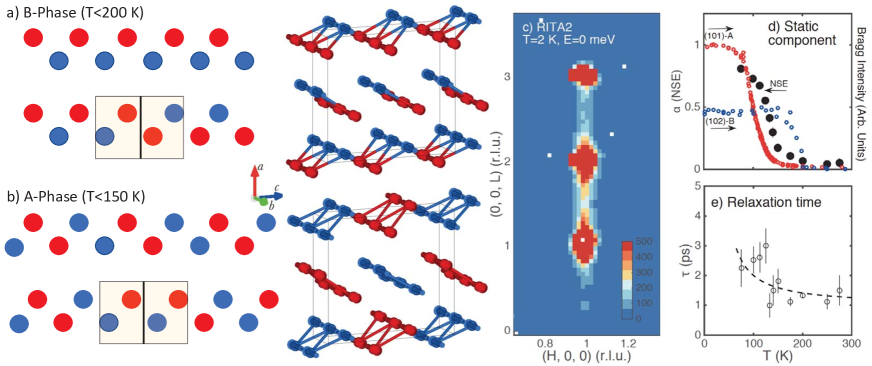
The () and () magnetic structures are illustrated in Fig. 1 and with the magnetic moments aligned along the axis (antiparallel arrangements denoted as red and blue). Two possible antiphase boundaries along the -axis are also illustrated. In panel , the boundary separates two high temperature () phase structures and locally has the magnetic structure of the low temperature phase () and also carries a net ferromagnetic moment. A similar situation is presented in panel for the low temperature phase. The momentum broadened rod of diffuse scattering characterizing these boundaries is reproduced in panel . Stock et al. (2016)
High resolution neutron spectroscopy (Fig. 1 which plots the static fraction as a function of temperature) finds these boundaries are predominately static on the GHz timescale below 100 K. The freezing of the boundaries occurs below the onset of phase () order measured by the (102) magnetic Bragg peak and also higher then the onset of phase () order probed through measurements of (101). The relaxational timescale measured with spin echo is displayed in panel where the dashed line is a plot of with fixed at the bulk magnetic anisotropy gap of 5 meV measured with neutron spectroscopy. Stock et al. (2016) The data is consistent with antiphase boundaries relaxing with an energy fixed by the bulk spin anisotropy.
The presence of static boundaries separating and order parameters brings the possibility of magnetic states that have different properties from the bulk, termed orphan spins. Moessner and Berlinsky (1999); Schiffer and Daruka (1997); Rehn et al. (2017) We apply neutron diffraction and inelastic scattering to identify and characterize these states. Further experimental details are provided in the supplementary information.
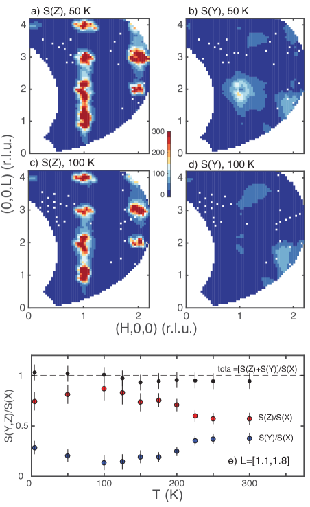
We first investigate the static structure of the antiphase boundaries using the DNS polarized diffractometer applying an polarization geometry. Fig. 2 illustrates the background corrected magnetic scattering originating from Fe3+ moments pointing along and (with vertical and parallel to the crystallographic axis and in the horizontal (H0L) scattering plane and perpendicular to ). Panels plot the magnetic intensity at 100 K and 50 K displaying two components - momentum resolution limited Bragg peaks at the integral (H,0,L) positions, corresponding to the long-range bulk structure, and a component which is broadened along the (1, 0, L) direction originating from short range spin correlations associated with the antiphase boundaries. The intensity contours illustrate that while most of the low-temperature magnetic scattering originates from spins aligned parallel to the -axis (Z direction), there is a measurable momentum broadened fraction of the intensity originating from moments perpendicular to this direction along . Panel plots the temperature evolution of the two components divided by the total magnetic intensity from the direction showing a significant fraction of spins jam perpendicular to the crystallographic -axis while the Fe3+ moments reorient from () phase to () phase order on cooling. The polarized results illustrate that there is a gradual change in the spin direction across the domain wall reminiscent of a “Bloch” wall instead of a fully discontinuous 180∘ “Neel” type boundary.
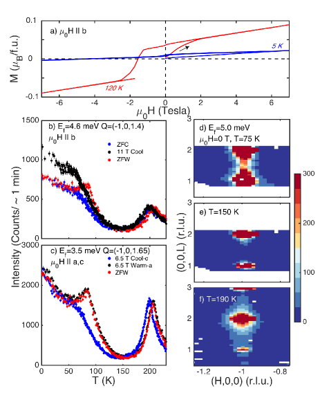
We now investigate whether these boundaries are tunable with an applied magnetic field. Papanicolaou (1998) Magnetization loops at 120 K and 5 K in Fig. 3 find an uncompensated remanent moment when the field is applied along . Panels illustrated the temperature and magnetic field dependence of the elastic diffuse scattering (RITA2 with unpolarized neutrons) at =(-1, 0, 1.4) and (-1, 0, 1.65) under different applied field conditions and representative (H0L) maps are displayed in panels . The peak in intensity at 200 K (panels ) is associated with critical scattering of the high temperature phase ordering (panels ). A minimum in the temperature dependent intensity (panels ) is seen at 150 K before rod like scattering along L characteristic of static antiphase boundaries forms (panel at 75 K). Panels show that the intensity is hysteretic in temperature with a peak forming at 100 K on warming analogous to localized structures in disordered materials (for example ferroelectric K1-xLixTaO3 Stock et al. (2014)).
Fig. 3 and also display the temperature dependence of this diffuse scattering cross section in the case of differing field conditions. When cooling takes place in a 11 T field parallel to the axis (panel ), the diffuse scattering is enhanced in comparison to the zero field cooled (ZFC) temperature sweep. No field dependence in this enhancement was observed for greater than 1 T and the effect was observed to freeze in for cooling below 150 K. Panel illustrates that this enhancement is largely reduced when the field is perpendicular to the axis as shown using a horizontal magnetic field of 6.5 T. The comparatively small changes with the field perpendicular to the axis is consistent with the relatively small number of spins jammed perpendicular to discussed above in the context of Fig. 2. Due to kinematic constraints associated with the horizontal magnet, an Ef=3.5 meV was used providing different intensity ratios for the diffuse scattering measured at 200 K in comparison to base temperature owing to differing energy resolutions and spectrometer configurations. Therefore, cooling with the field aligned along the direction of dominant bulk staggered magnetization (crystallographic axis) results in an enhancement of diffuse scattering indicative of a larger density of antiphase boundaries. Orienting the field perpendicular does not result in any such enhancement.
The response of the diffuse scattering to an applied magnetic field that tracks the dominant orientation indicates that these boundaries have a -axis uncompensated, ferromagnetic, moment. While this conclusion is drawn from the finite- response, magnetization (panel , probe) corroborates the presence of a localized ferromagnetic moment and further data presented in the supplementary information show the momentum dependence is indeed peaked at =0. One such real-space scenario for this to occur is illustrated in Fig. 1 which schematically plots an antiphase boundary in the high temperature phase. Locally, the orphaned spins in the boundary have the structure of the low temperature phase and also carry a net ferromagnetic moment which originates in the field dependence presented in Fig. 3. This local ferromagnetism occurs even though the magnetic structure is globally antiferromagnetic.
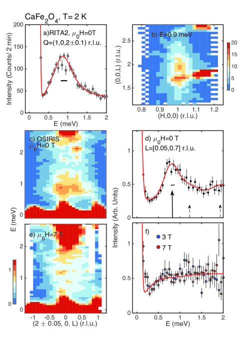
We now apply spectroscopy to study the energy spectra associated with these antiphase boundaries. Magnetic boundary, or edge, states have been predicted in low dimensional magnets Ng (1994) and superconductors Kohno et al. (1999) and experimentally observed in insulating and disordered quantum magnets Xu et al. (2007); Kenzelmann et al. (2003); Els et al. (1998); Schmidiger et al. (2016); Stock et al. (2009). Motivated by the possibility of novel states near these boundaries, we apply neutron spectroscopy in Fig. 4 by searching for bound magnetic excitations within the anisotropy induced gap of 5 meV. Fig. 4 illustrates a constant momentum scan (RITA2) showing a peak at 0.9 meV. The peak is significantly broader than resolution (solid horizontal line of 0.25 meV) with a full width in energy of =0.72 0.15 meV and approximately an order of magnitude weaker in intensity than the bulk dispersive spins waves. Panel plots a constant energy slice indicating strong correlations along the axis and weak correlations along mimicking the elastic magnetic diffuse scattering cross section (Fig. 1 ). Figure 4 panel shows an energy slice using high resolution neutron spectroscopy from the OSIRIS backscattering spectrometer. The mode at 0.9 meV, while broader than resolution, displays no momentum dispersion and hence no on-site molecular field, indicative of isolated or orphan spins states.
The energy scale of 0.9 meV can be reconciled if we consider a simple edge state consisting of isolated clusters. Such clusters consist of Fe3+ spins coupled with an exchange constant along the crystallographic axis with an interaction Hamiltonian of (where is summed over the cluster). Buyers et al. (1984); Furrer and Waldmann (2013) The simplest state would consist of an isolated dimer with a singlet =0 ground state and higher energy levels of =1,2,3,4,5. The energy scale to excite such a dimer from the ground state to an excited state is which has been estimated to be 0.94 0.19 meV based on high energy spectroscopy of the bulk magnetic dispersion discussed previously. Stock et al. (2016) This is in agreement with the peak position in Fig. 4 . However, Fig. 4 also displays a continuum of excitations that extend from E=0.9 meV to higher energies which can be understood in terms of larger clusters such as trimers which would display discrete excitations at further energies. The energy spectrum for the above Hamiltonian based on a trimer would display lowest excitation energies of 1.5, 2.5, and 3.5. Svensson et al. (1978) The solid line in panel is a fit to the OSIRIS data to a series of lifetime shortened excitations fixed at the dimer excitation level and the two lowest energy trimer levels with the intensity reflecting the probability of such states. From this fit to dimer and trimers, an estimate of =0.78 0.17 meV which is in agreement with the value obtained from fitting the dispersive band excitations.
Fig. 4 and illustrate the response of these cluster states to an applied magnetic field showing that applied fields of 3 and 7 T along the crystallographic axis are sufficient to smear the lowest energy state in energy. These results are consistent with Zeeman splitting of lifetime shortened multiplets originating from cluster excitations. The fit in panel is to a single energy broadened relaxational mode. The results of this analysis shows that the exchange constant derived from higher energy bulk spin wave measurements and the localized excitations from the “in-gap” states can be consistently understood by the presence of clusters of spins located near the antiphase boundaries. The energy scale of these cluster states is low enough to be tuned with a field.
The magnetic bound states display weak dynamic correlation lengths along , while much longer length scales along , therefore mimicking the planar antiphase boundaries found in diffraction and differing from the spin-waves onset at much higher energies. The lack of a measurable on-site molecular field evidenced from the momentum dependence indicates that these orphaned spins are decoupled from the and magnetic order parameters. These orphaned states exist at the boundary between the two order parameters allowing them to coexist in CaFe2O4 at low temperatures. Such states have been proposed as a means of stabilizing spin liquid states in honeycomb lattices Flint and Lee (2013) and may exist in triangular magnets with much smaller exchange interactions resulting in strong low-energy fluctuations. Lhotel et al. (2011); Stock et al. (2010); Nambu et al. (2015). Orphaned spins maybe a means of decoupling differing magnetic orders when a number of different order parameters exist with similar energy scales.
In summary, we have shown the presence of ferromagnetic edge states in CaFe2O4 originating from antiphase boundaries separating competing magnetic order parameters. Spectroscopic evidence points to these edge states consisting of clusters of orphaned spins.
Acknowledgements.
This work was supported by the EPSRC, the Carnegie Trust for the Universities of Scotland, the Royal Society of London, and Royal Society of Edinburgh, the STFC, EU-NMI3, NSF (No. DMR-1508249), and the Swiss spallation neutron source (SINQ) (Paul Scherrer Institute, Villigen, Switzerland). The work at Rutgers was supported by the DOE under Grant No. DE-FG02-07ER46382. The work at Postech was supported by the Max Planck POSTECH/KOREA Research Initiative Program [Grant No. 2011-0031558] through NRF of Korea funded by MSIP. We are grateful to C. Mudry for helpful discussions.References
- Shockley (1939) W. Shockley, Phys. Rev. 56, 317 (1939).
- Mills and Saslow (1968) D. L. Mills and W. M. Saslow, Phys. Rev. 171, 488 (1968).
- Mills (1968) D. L. Mills, Phys. Rev. Lett. 20, 18 (1968).
- Li et al. (2003) J. Li, L. Zhou, C. T. Chan, and P. Sheng, Phys. Rev. Lett. 90, 083901 (2003).
- Enoch et al. (2002) S. Enoch, G. Tayeb, P. Sabouroux, N. Guérin, and P. Vincent, Phys. Rev. Lett. 89, 213902 (2002).
- Overhauser and Daemen (1989) A. W. Overhauser and L. L. Daemen, Phys. Rev. Lett. 62, 1691 (1989).
- Hess et al. (1989) H. F. Hess, R. B. Robinson, R. C. Dynes, J. M. Valles, and J. V. Waszczak, Phys. Rev. Lett. 62, 214 (1989).
- Hayashi et al. (1998) N. Hayashi, T. Isoshima, M. Ichioka, and K. Machida, Phys. Rev. Lett. 80, 2921 (1998).
- Pan et al. (2000) S. H. Pan, E. W. Hudson, A. K. Gupta, K.-W. Ng, H. Eisaki, S. Uchida, and J. C. Davis, Phys. Rev. Lett. 85, 1536 (2000).
- Hasan and Kane (2010) M. Z. Hasan and C. L. Kane, Rev. Mod. Phys. 82, 3045 (2010).
- Su and Schrieffer (1980) S. P. Su and J. R. Schrieffer, PNAS 77, 5626 (1980).
- Heeger et al. (1988) A. J. Heeger, S. Kivelson, J. R. Schrieffer, and W. P. Su, Rev. Mod. Phys. 60, 781 (1988).
- Roth and Bleier (1987) S. Roth and H. Bleier, Adv. Phys. 36, 385 (1987).
- Rothberg et al. (1986) L. Rothberg, T. M. Jedju, S. Etemad, and G. L. Baker, Phys. Rev. Lett. 57, 3229 (1986).
- Kimel et al. (2004) A. V. Kimel, A. Kirilyuk, A. Tsvetkov, R. V. Pisarev, and T. Rasing, Nature 429, 850 (2004).
- Jungwirth et al. (2016) T. Jungwirth, X. Marti, P. Wadley, and J. Wunderlich, Nat. Nanotechnol. 11, 231 (2016).
- Shiino et al. (2016) T. Shiino, S. H. Oh, P. M. Haney, S. W. Lee, G. Go, B. G. Park, and K. J. Lee, Phys. Rev. Lett. 117, 087203 (2016).
- Gomonay et al. (2016) O. Gomonay, T. Jungwirth, and J. Sinova, Phys. Rev. Lett. 117, 017202 (2016).
- Kampfrath et al. (2011) T. Kampfrath, A. Sell, G. Klatt, A. Pashkin, S. Mahrlein, T. Dekorsy, M. Wolf, M. Fiebig, A. Leitenstorfer, and R. Huber, Nat. Photon. 5, 31 (2011).
- Bode et al. (2006) M. Bode, E. Y. Vedmedenko, K. von Bergmann, A. Kubetzka, P. Ferriani, S. Heinze, and R. Wiesendanger, Nat. Mater. 5, 477 (2006).
- Meiklejohn and Bean (1956) W. H. Meiklejohn and C. P. Bean, Phys. Rev. 102, 1413 (1956).
- Meiklejohn and Bean (1957) W. H. Meiklejohn and C. P. Bean, Phys. Rev. 105, 904 (1957).
- Zhang et al. (2013) L. Zhang, J. Ren, J.-S. Wang, and B. Li, Phys. Rev. B 87, 144101 (2013).
- Decker and Kasper (1957) D. F. Decker and J. S. Kasper, Acta Cryst. 10, 332 (1957).
- Hill et al. (1956) P. M. Hill, H. S. Peiser, and J. R. Rait, Acta Cryst. 9, 981 (1956).
- Allain et al. (1966) Y. Allain, B. Boucher, P. Imbert, and M. Perrin, C. R. Acad. Sc. Paris 263, 9 (1966).
- Watanabe et al. (1967) H. Watanabe, H. Yamauchi, M. Ohashi, M. Sugiomoto, and T. Okada, J. Phys. Soc. Japan 22, 939 (1967).
- Das et al. (2016) R. Das, S. Karna, Y. C. Lai, and F. C. Chou, Cryst. Growth Des. 16, 499 (2016).
- Obata et al. (2013) K. Obata, Y. Obukuro, S. Matsushima, H. Nakamura, M. Arai, and K. Kobayashi, J. Ceram. Soc. Jpn. 121, 766 (2013).
- Stock et al. (2016) C. Stock, E. E. Rodriguez, N. Lee, M. A. Green, F. Demmel, R. A. Ewings, P. Fouquet, M. Laver, C. Niedermayer, Y. Su, K. Nemkovski, J. A. Rodriguez-Rivera, and S. W. Cheong, Phys. Rev. Lett. 117, 017201 (2016).
- Moessner and Berlinsky (1999) R. Moessner and A. J. Berlinsky, Phys. Rev. Lett. 83, 3293 (1999).
- Schiffer and Daruka (1997) P. Schiffer and I. Daruka, Phys. Rev. B 56, 13712 (1997).
- Rehn et al. (2017) J. Rehn, A. Sen, and R. Moessner, Phys. Rev. Lett. 118, 047201 (2017).
- Papanicolaou (1998) N. Papanicolaou, J. Phys.: Condens. Matter 10, L131 (1998).
- Stock et al. (2014) C. Stock, P. M. Gehring, G. Xu, D. Lamago, D. Reznik, M. Russina, J. Wen, and L. A. Boatner, Phys. Rev. B 90, 224302 (2014).
- Ng (1994) T. K. Ng, Phys. Rev. B 50, 555 (1994).
- Kohno et al. (1999) H. Kohno, H. Fukuyama, and M. Sigrist, J. Phys. Soc. Jpn. 68, 1500 (1999).
- Xu et al. (2007) G. Xu, C. Broholm, Y. A. Soh, G. Aeppli, J. F. DiTusa, Y. Chen, M. Kenzelmann, C. D. Frost, T. Ito, K. Ota, and H. Takagi, Science 317, 1049 (2007).
- Kenzelmann et al. (2003) M. Kenzelmann, G. Xu, I. A. Zaliznyak, C. Broholm, J. F. DiTusa, G. Aeppli, T. Ito, K. Oka, and H. Takagi, Phys. Rev. Lett. 90, 087202 (2003).
- Els et al. (1998) G. Els, G. S. Uhrig, P. Lemmens, H. Vonberg, P. H. M. van Loosdrecht, G. Guntherodt, O. Fujita, J. Akimitsu, G. Ghalenne, and A. Revcolevschi, Europhys. Lett. 43, 463 (1998).
- Schmidiger et al. (2016) D. Schmidiger, K. Y. Povarov, S. Galeski, N. Reynolds, R. Bewley, T. Guidi, J. Ollivier, and A. Zheludev, Phys. Rev. Lett. 116, 257203 (2016).
- Stock et al. (2009) C. Stock, W. J. L. Buyers, K. C. Rule, J. H. Chung, R. Liang, D. Bonn, and W. N. Hardy, Phys. Rev. B 79, 184514 (2009).
- Buyers et al. (1984) W. J. L. Buyers, T. M. Holden, E. C. Svensson, and D. J. Lockwood, Phys. Rev. B 30, 6521 (1984).
- Furrer and Waldmann (2013) A. Furrer and O. Waldmann, Rev. Mod. Phys. 85, 367 (2013).
- Svensson et al. (1978) E. C. Svensson, M. Harvey, W. J. L. Buyers, and T. M. Holden, J. Appl. Phys. 49, 2150 (1978).
- Flint and Lee (2013) R. Flint and P. A. Lee, Phys. Rev. Lett. 111, 217201 (2013).
- Lhotel et al. (2011) E. Lhotel, V. Simonet, J. Ortloff, B. Canals, C. Paulsen, E. Suard, T. Hansen, D. J. Price, P. T. Wood, A. K. Powell, and R. Ballou, Phys. Rev. Lett. 107, 257205 (2011).
- Stock et al. (2010) C. Stock, S. Jonas, C. Broholm, S. Nakatsuji, Y. Nambu, K. Onuma, Y. Maeno, and J.-H. Chung, Phys. Rev. Lett. 105, 037402 (2010).
- Nambu et al. (2015) Y. Nambu, J. S. Gardner, D. E. MacLaughlin, C. Stock, H. Endo, S. Jonas, T. J. Sato, S. Nakatsuji, and C. Broholm, Phys. Rev. Lett. 115, 127202 (2015).