Progress on Experiments towards LWFA-driven Transverse Gradient Undulator-Based FELs
Abstract
Free Electron Lasers (FEL) are commonly regarded as the potential key application of laser wakefield accelerators (LWFA). It has been found that electron bunches exiting from state-of-the-art LWFAs exhibit a normalized 6-dimensional beam brightness comparable to those in conventional linear accelerators. Effectively exploiting this beneficial beam property for LWFA-based FELs is challenging due to the extreme initial conditions particularly in terms of beam divergence and energy spread. Several different approaches for capturing, reshaping and matching LWFA beams to suited undulators, such as bunch decompression or transverse-gradient undulator schemes, are currently being explored. In this article the transverse gradient undulator concept will be discussed with a focus on recent experimental achievements.
keywords:
Laser wakefield accelerator , transverse gradient undulator , superconducting , beam transport , FEL1 Introduction
Due to the extremely high longitudinal electric fields present in laser- or beam-driven plasma waves, plasma wakefield accelerated electron bunches can gain energies sufficient to generate synchrotron radiation in the X-ray regime within only a few millimetres to centimeters of acceleration length. It is common sense that fully exploiting the potential of laser-driven plasma accelerators could bring laboratory scale, cost efficient, highly brilliant radiation sources for the EUV and X-ray range into reach, with radiation properties which are so far only available at large-scale facilities.
Several different mechanisms of radiation generation at laser wakefield accelerators (LWFA) are being investigated and partially already used, both for diagnosis of the LWF accelerated electron bunches and for applications. The most prominent examples are the generation of betatron radiation during the acceleration process [1, 2], Thomson back scattering and inverse Compton scattering [3, 4, 5] of a laser pulse colliding with the LWF accelerated electron bunch and LWFA-driven free electron lasers (FELs) [6, 7, 8, 9]. Similar to the classical radiation sources, the radiation generated by these different mechanisms is attractive for different classes of applications, particularly for time resolved methods benefiting from the ultra-short radiation pulses which can be generated. Betatron radiation as the simplest of the above schemes is already being successfully applied in imaging and spectroscopic applications [10, 11].
For given electron source properties, particularly for given electron energy and average beam current, the free electron laser scheme is superior to all other schemes in terms of spectral radiation power, (small) radiation energy bandwidth and coherence. It is, therefore, the scheme of choice for a number of important classes of applications like EUV lithography (integrated circuit fabrication), phase contrast imaging (medical imaging) or single-molecule diffraction (life sciences). Obviously, such applications would tremendously benefit from the availability of laboratory-scale FELs which could be integrated into the respective fabrication, hospital or laboratory infrastructure.
The FEL scheme, on the other hand, places the highest demands on the beam quality provided by the accelerator. As it has been found, [12], laser wakefield accelerators can provide an initial normalized 6D beam brightness comparable to that of conventional state-of-the-art accelerators, which is a precondition for making them suited to drive an FEL. It is, however, not straightforward to derive advantage from this initial condition for FEL applications: particularly an energy spread on the percent level and an initial beam divergence in a several milliradian range pose serious challenges to the beam capture and transport and, if not counteracted, compromise the FEL amplification.
Therefore, to realize LWFA-driven FELs, an appropriate phase space manipulation preparing the plasma-accelerated electron bunches for the FEL amplification process is indispensable and a modification also of the FEL undulators might be beneficial. Two schemes for driving FELs with large-energy spread beams have been proposed: longitudinal decompression of the beam can be used to reduce the slice energy spread over the FEL cooperation length [13, 14] on the one hand and the scheme based on transverse gradient undulators (TGUs) on the other hand, which will be discussed in the following.
The idea of the TGU scheme [15, 16] is to imprint a transverse spectral dispersion on the beam, i.e. to correlate the particle energy with the particle’s transverse position. The amplitude of the magnetic flux density inside the TGU is a function of the transverse position as well. If the transverse electron beam dispersion and the transverse magnetic field distribution are properly matched the reference particles of all energies present in the beam oscillate with the same frequency and radiate at the same wavelength
| (1) |
with the undulator period length, the Lorentz factor, and the magnetic flux density amplitude of the undulator. Thinking of the electron bunch as being composed of a set of mono-energetic sub-bunches, it is now the effective energy spread introduced by the finite transverse size of these sub-bunches together with the transverse magnetic field gradient rather than the overall energy spread of the bunch which limits the FEL amplification. Huang et al. [17] have shown that this limitation is normally much less severe than that imposed by the energy spread and that with the TGU scheme — for the investigated examples — a shorter gain length and higher saturation power than without a TGU and even than with a decompression scheme can be achieved, bringing compact LWFA-driven FELs into reach.
In this contribution, we review the ongoing experimental projects towards TGU-based LWFA-driven FELs and the results achieved in these projects so far.
2 Experimental Projects towards LWFA-TGU-FELs
Two collaborations are currently carrying out experimental projects towards TGU-based LWFA-driven FELs: A consortium of the Chinese institutes SIOM (Shanghai Institute of Optics and Fine Mechanics) and SINAP (Shanghai Institute of Applied Physics) with the SLAC National Accelerator Laboratory, US, on the one hand, and a consortium of the KIT, the Helmholtz Institute Jena and the Friedrich-Schiller-University Jena in Germany, on the other hand.
The SIOM/SINAP/SLAC TGU beam line is being set up at the SIOM laser facility. In the SIOM LWFA set-up, a superposition of two supersonic gas jets is used to control the plasma density profile and thereby the internal injection and the wakefield acceleration process. In this way electron bunches with an energy tunable between 200 and , energy spreads in the order of and a shot-to-shot energy jitter of are produced, featuring bunch charges of up to and a beam divergence in the order of [18]. For the TGU experiment, a design beam energy of has been chosen [19].
For transporting the beam and matching the dispersion and beta functions to the TGU, a beam line with a single deflection is foreseen. For the beam capture, a strong quadrupole triplet, partly in vacuum, is foreseen, followed by the deflecting dipole and a matching quadrupole triplet. To mitigate the increase of the projected normalized emittance introduced by the energy spread of the beam as well as non-linear dispersion effects generated by the strong quadrupoles, a correction scheme with three sextupoles is used which requires sextupole strengths in the order of [19]. These and the in-vacuum quadrupoles are currently under technical development, whereas the deflecting dipole and the second triplet together with a set of four permanent magnet transverse gradient undulators are already in place. Each of these undulators features 40 periods with a period length of , a central deflection parameter and a relative transverse gradient
| (2) |
of [20].
The Jena-Karlsruhe experiments have so far been performed at the JETI-40 laser facility in Jena. Whereas the experimental setup at SIOM directly aims at a TGU-FEL demonstration, our experimental approach is taking the intermediate step of investigating the generation of spontaneous TGU radiation. The design energy for the Jena-Karlsruhe set-up is . A very large energy acceptance of is aimed at, covering both, the single-bunch energy spread and the shot-to-shot energy jitter. The beam transport, as discussed in more detail below, has an achromat-like dogleg lattice with two deflecting dipoles, the TGU is a superconducting undulator with a cylindrical pole shape.
3 Progress on Experiments in the Jena-Karlsruhe Project
3.1 Superconducting TGU
At KIT a 40-period superconducting transverse gradient undulator has been realized and successfully tested in the vertical bath cryostat and field measurement set-up CASPER.
The design, realisation and test of this TGU from the very beginning aimed at demonstrating the feasibility of the short period and high transverse field gradient at a still sufficiently high -parameter, which is required for a compact and bright LWFA-driven EUV or X-ray source.
| period length | |
|---|---|
| gap @ symmetry axis | |
| pole radius | |
| flux density ampl. | |
| undulator parameter | 1.1 |
| transverse gradient | |
| energy acceptance |
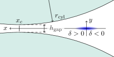
Particularly the demand for a high transverse gradient led to the choice of a cylindrical pole shape as depicted in Fig. 1. Compared to a transverse taper the cylindrical geometry has several advantages [16, 21]. The achievable transverse magnetic flux density gradient is much higher. The magnetic flux density profile exhibits a flexion point around which the field gradient is constant to a very good approximation. Lastly, this geometry is comparably simple to realize, particularly in case of superconducting undulators. The main parameters of the SCTGU resulting from the magnetic design optimization [22, 23] are summarized in Table 1.
Due to the transverse gradient in the magnetic flux density the particles traveling through the TGU experience a net kick towards the lower-field region in each period which leads to a transverse drift. This ponderomotive effect can be suppressed by superimposing a -dependent correction field constant in longitudinal direction. In case of the SCTGU, this correction field is a weak () combined dipole and shifted sextupole field which is generated by two long, narrow racetrack coils which are inserted in the coil formers. In order to avoid distortions of this correction field, the undulator is entirely iron-free.
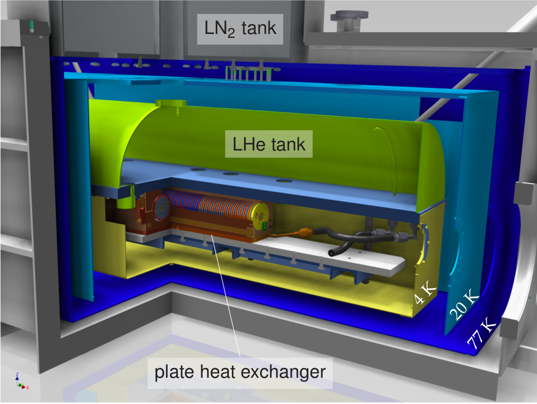
Both the undulator coils and the correction coils are wound from Nb-Ti multifilament wires. For operating the undulator at the JETI beam line a specialized cryostat was constructed. A cutaway view of the cryostat is shown in Fig. 2. The undulator is placed in the beam vacuum and indirectly cooled through plate heat exchangers with a liquid Helium flow from a reservoir placed on top of the undulator.
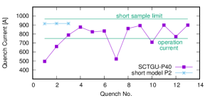
The SCTGU was realized in-house in three steps: first the general winding geometry and the quench performance of single 2-period short model test coils were tested and improved, second a complete 2-period short model was built, tested and characterized and eventually the full-scale device was realized, tested and partially characterized in the bath cryostat CASPER. Figure 3 shows the quench history of the short model P2 and the full-scale SCTGU-P40. The short model immediately reached a stable quench current close to the short sample limit of the superconducting wire. The SCTGU-P40, after 13 quenches has not yet reached entirely stable conditions. However, the quench history indicates that it will be safely operable at the design operation current of .
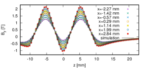
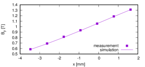
For the magnetic characterization of both devices a Hall probe array supplied by AREPOC s.r.o., Slovakia, was employed, measuring the vertical (-) component of the magnetic flux density at seven equidistant transverse (-) positions around the beam position in the TGU gap. In case of the short model, this array could be scanned through the undulator gap in longitudinal (-) direction. Due to geometrical limitations of the set-up in CASPER, a field measurement at only one fixed position was performed. The results of these measurements, shown in Fig. 4, show excellent agreement with the theoretical predictions. Free Electron Lasers (FEL) are commonly regarded as the potential key application of laser wakefield accelerators (LWFA). It has been found that electron bunches exiting from state-of-the-art LWFAs exhibit a normalized 6-dimensional beam brightness comparable to those in conventional linear accelerators. Effectively exploiting this beneficial beam property for LWFA-based FELs is challenging due to the extreme initial conditions particularly in terms of beam divergence and energy spread. Several different approaches for capturing, reshaping and matching LWFA beams to suited undulators, such as bunch decompression or transverse-gradient undulator schemes, are currently being explored. In this article the transverse gradient undulator concept will be discussed with a focus on recent experimental achievements.
3.2 Beam transport
3.2.1 Matching conditions and beam optics
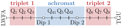
Our beam transport line design started off with the (geometrically) symmetric magnet lattice schematically shown in Fig. 5, consisting of a matching quadrupole triplet close to the LWFA, an achromat-like dogleg chicane and a second matching triplet at the entrance of the TGU [24, 25].
Approximative matching conditions for the TGU can be derived from the undulator equation as the resonance condition and a linear TGU model which yields
| (3) |
for the linear dispersion [17, 26] and
| (4) | ||||
for the beam size and divergence, respectively, inside the undulator [27]. Here, is the geometric emittance of a monochromatic slice of the electron beam, is to be understood as the relative wavelength bandwidth condition which in case of spontaneous undulator radiation scales like with the number of undulator periods, and in an idealizing case of FEL amplification like the Pierce parameter with . In our case, these estimations lead to the condition that the slice transverse beam size in the deflection direction should be clearly below inside the undulator.
It is worth noting that a TGU due to the transverse field gradient with periodically alternating field direction and therefore also alternating sign of the gradient forms a periodically focussing and defocussing (FODO) structure. Thus there exists a periodic solution for inside the undulator. For the SCTGU operated at the design field amplitude and with the design beam energy of the amplitude of the periodic betatron function turns out to be too large () to fulfill the above beam size condition. Consequently, a matching scheme with an external focusing to the undulator center was chosen for . For the vertical direction, a matching to the constant beta-function solution is favorable, which exists due to the natural focusing present in any planar insertion device.
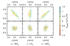
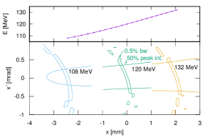
For a better understanding of the matching conditions for finite-emittance beams we investigated the spontaneous radiation fields of the particles of a finite-emittance bunch tracked through the undulator [27]. Figure 6 shows the phase space distributions in and at the entrance, center and exit of the TGU resulting from a simulation with WAVE [28] for a 100-period TGU with our design parameters. The simulation was done for a (slice) particle beam at the design beam energy with a slice geometric emittance , and focused in to the TGU center with . The color code reflects the relative deviation of the wavelength of the radiation emitted by the respective particle from the design wavelength . This result suggests that there is virtually no correlation between the wavelength detuning and the position in the phase space, whereas the strong correlation between detuning and position in phase space is dominated by the effect of the finite beam size in the beam waist, while the detuning due to the beam divergence appears much weaker: low values are favoured. Such tracking simulations performed for several beam slices at discrete beam energies may be used to establish overall matching conditions for the TGU in terms of optimized dispersion conditions and acceptance areas in phase space. Figure 7 shows the result for the Jena-Karlsruhe TGU extended to 100 periods and beam energies of .
| initial | final | |
|---|---|---|
| 0 | 2.6 | |
| 0 | 0 | |
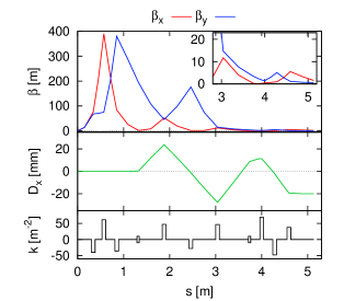
Table 2 summarizes the matching conditions at the exit of the LWFA (initial), estimated from the plasma wake structure size and the beam divergence measurements, and at the entrance of the TGU (final) as derived from the above considerations. The initial and final triplet of the beam transport lattice can be matched to the initial and final conditions, and in a second step the dispersion is matched through an adjustment of the achromat cell and the final triplet. The result of this matching is shown in Fig. 8 for the design beam energy .
Clearly, to make this matching work for a sufficiently wide band of electron energies, higher order corrections are necessary. For the final realization stage we foresee the application of combined-function quadrupole-sextupole magnets at the positions of , , , .
We note that the shown optics without being optimized for bunch length preservation leads to only a moderate bunch lengthening with the transport matrix elements , and . There is probably the potential to optimize the lattice towards a close to isochronous beam transport.
3.2.2 Experimental realization
In the experimental realization of our beam transport concept, we started with a linear beam transport line consisting of the first quadrupole triplet and the achromat-like dogleg chicane cell. The idea is to investigate the TGU radiation for a range of electron energies by consecutively adjusting the focusing for each energy while keeping the dispersion fixed. For this approach fewer degrees of freedom are required than in the fully matched and chromatically corrected case, allowing us to omit the second matching triplet.
The beam transport line was set up at the JETI-40 laser facility in Jena, at that time providing laser pulses with a pulse duration of , a pulse energy of up to before compression, and a peak intensity at the target of . For the plasma accelerator, a gas cell () with a He and N2 gas mixture was used.
To allow for maximum experimental flexibility, the complete beam line is realized with electromagnets placed in an about 3-m long vacuum box connected to the vacuum chamber of the LWFA. The chicane dipoles were supplied by GMW Associates, the in-vacuum quadrupoles and later on combined function magnets are in-house designed and manufactured. The philosophy behind that is again experimental flexibility: the magnets are comparably simple, inexpensive and thanks to a modular design easy to modify. In the current set-up, two types of quadrupoles with a gap radius , a magnetic length of and a nominal field gradient of and , respectively, were used [29].
All magnets were characterized by 3D Hall probe scans at our magnetic measurement set-up [30]. Besides a classical 3D mapping of the three Cartesian components of the magnetic flux density the method of circular Hall probe scans was applied which yields a 1D map of the multipole components of the magnetic field along the axis. This mapping can very effectively be used in tracking simulations taking into account the fringe fields and multipole errors of the real magnets to a good approximation [31]. We used this representation in comparison to a simple hard edge model in our tracking simulations in order to disentangle general properties of the beam transport optics from effects due to individual properties of the non-perfect magnets.
A LANEX screen insertable at three longitudinal positions — after the first triplet, after the central quadrupole of the achromat cell and after the final dipole — and an electron spectrometer taking the place of the undulator served as electron beam diagnostics in this experiment.
3.2.3 Experimental results
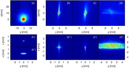
In the experiments on the beam transport were performed at electron energies in the range of due to limitations of the laser system present at that time. An image of the initial beam at the LANEX screen positioned after the gas cell, averaged over 180 consecutive shots, is shown in Fig. 9 (a). This image is resulting from the convolution of the divergence of the individual bunches — (FWHM) on average — and a pointing jitter of (rms). The asymmetry in the vertical profile originates from the latter. This rather unstable pointing implied that averaging over about 30 consecutive shots was necessary in each step of the experiment. The asymmetry of the initial averaged profile is visible also in the averaged profiles of the captured and transported beam.
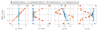
Since also the mean pointing direction of the electron bunches differed slightly from that of the laser to which the magnets were pre-aligned, the first step of the experiment was to adjust the magnet alignment with respect to the mean beam axis. The transverse position of each individual quadrupole was remotely adjustable in two (first triplet) or, respectively, one (second triplet) translational degrees of freedom. If the magnet is turned on and scanned in its focusing direction, the profile of the focused beam captured on a subsequent screen can be used for a beam-based alignment of the magnet. Tracking simulations show that the skewness of the beam profile in focused direction is particularly sensitive to quadrupole misalignments, both translational about the axis perpendicular and rotational about the transverse axis parallel to the focusing plane. The variance and kurtosis of the profile are sensitive to translational alignment errors only. These characteristics shown in Fig. 10 can in principle be utilized for a successive beam-based alignment of the magnet in the various transverse degrees of freedom. Also shown in the figure is a comparison of tracking results using the above mentioned 1D multipole representation of the magnet deduced from the circular Hall probe scans with those using an analytic hard-edge model. The influence of the fringe fields and multipole errors of the real magnets on the beam profile characteristics is visible, but small.
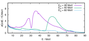
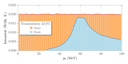
After the beam-based alignment of the first triplet it was possible to focus the electron bunches into the electron spectrometer downstream from the gas cell. The electron energy spectra measured with focusing settings for three different energies are shown in Fig. 11. For comparison, the spectral transmission function for the triplet setting for deduced from tracking simulations is shown.
Figure 9 (b)–(d) shows the averaged electron beam images at different beam screen positions taken at the further steps of setting up the beam transport to the TGU: (b) using the first triplet focusing to the screen downstream from the gas cell, (c) using the first triplet focusing to the screen downstream with the two chicane dipoles on and (d) using additionally the quadrupoles of the achromat cell and with the setting satisfying the matching conditions for the TGU (at ) — note that in this case the beam focus is about behind the beam screen.
Figure 9 (b’)–(d’) show for comparison the results of tracking simulations investigating the influence of the initial beam properties on beam profiles which observable for the respective optics settings. These simulations assume perfect magnets and magnet alignments and a Gaussian initial beam. Such simulations give an idea how the initial beam properties in terms of divergence and energy spread contribute to the features observed. In Fig.9 (b’) and (b”) the images are shown that would be expected if the beam had a negligible energy spread. The large divergence of the initial beam has mainly the effect of increasing the spot size without affecting the Gaussian spot shape (b”), as the comparison to a beam with an initial beam divergence of (b’) shows. An additional increase of the energy spread (b”’) leads to the observed cross shape. Fig. 9 (c’) and (d’) do not represent a rigorous theoretical reproduction of the experimental results. These calculations guide our general understanding of the obtained experimental results and, more important, establish a starting point for preparing the next experimental steps and related modelling.
3.3 Next steps
Obviously, the next step is to set up the complete proof-of-principle experiment encompassing beam transport, transverse gradient undulator and photon diagnostics. The work on two major preparatory tasks is in progress. Firstly, the cryostat for the SCTGU has recently successfully been commissioned; a sliding system for scanning the above mentioned Hall probe array has been built and tested and will be installed along with the TGU in the cryostat for a full 2D magnetic characterization of the TGU.
Secondly, an improved positioning system for the quadrupoles is under construction which will provide a much better control over the alignment of the magnets and add the rotational and translational degrees of freedom which were missing in the above-described experiments.
4 Conclusion
Scaling considerations and simulations suggest that transverse-gradient undulator schemes are a valid option for realizing compact, laser wakefield accelerator-driven FELs. An experimental validation of the TGU concept is still due. The two major projects towards this experimental proof of principle conducted by SIOM/SINAP/SLAC on the one hand and FSU Jena/HI Jena/KIT on the other hand, follow different conceptual, experimental and technological approaches. On the side of the Jena-Karlsruhe project, major experimental achievements were the demonstration of the technical feasibility of high-transverse-gradient superconducting TGU and the successful performance of a pioneering experiment on beam capture, transport and matching at the LWFA at the JETI-40 laser facility. The electron beam generated by the LWFA could be controlled in a quite robust manner and transported over to the later position of the TGU. The beam transport line set-up deliberately was kept simple and flexible which turned out to be very useful in the experiment. However, due to the limited diagnostics available a thorough characterization and good control of the beam line components as well as accompanying simulations are essential for this kind of experiment.
So far, the experimental results indicate that the goal of a TGU radiation source driven by a LWFA is achievable.
5 Acknowledgement
The work described in this article has partially been supported by the German Federal Ministry of Education and Research under Grant 05K10VK2 and Grant 05K10SJ2.
References
- [1] Antoine Rousse, Kim Ta Phuoc, Rahul Shah, Alexander Pukhov, Eric Lefebvre, Victor Malka, Sergey Kiselev, Fréderic Burgy, Jean-Philippe Rousseau, Donald Umstadter, and Daniéle Hulin. Production of a kev x-ray beam from synchrotron radiation in relativistic laser-plasma interaction. Phys. Rev. Lett., 93:135005, Sep 2004.
- [2] Kim Ta Phuoc, Fréderic Burgy, Jean-Philippe Rousseau, Victor Malka, Antoine Rousse, Rahul Shah, Donald Umstadter, Alexander Pukhov, and Sergei Kiselev. Laser based synchrotron radiation. Physics of Plasmas, 12(2):023101, 2005.
- [3] P Catravas, E Esarey, and W P Leemans. Femtosecond x-rays from thomson scattering using laser wakefield accelerators. Measurement Science and Technology, 12(11):1828, 2001.
- [4] H. Schwoerer, B. Liesfeld, H.-P. Schlenvoigt, K.-U. Amthor, and R. Sauerbrey. Thomson-backscattered x rays from laser-accelerated electrons. Phys. Rev. Lett., 96:014802, Jan 2006.
- [5] Phuoc K. T., S. Corde, C. Thaury, V. Malka, A. Tafzi, J.P. Goddet, R.C. Shah, S. Sebban, and A. Rousse. All-optical compton gamma-ray source. Nature Photonics, 6, 2012.
- [6] K Nakajima, M Kando, T Kawakubo, T Nakanishi, and A Ogata. A table-top x-ray fel based on the laser wakefield accelerator-undulator system. Nuclear Instruments and Methods in Physics Research Section A: Accelerators, Spectrometers, Detectors and Associated Equipment, 375(1):593 – 596, 1996. Proceedings of the 17th International Free Electron Laser Conference.
- [7] F. Grüner, S. Becker, U. Schramm, E. Eichner, M. Fuchs, R. Weingartner, D. Habs, J. Meyer-Ter-Vehn, M. Geissler, M. Ferrario, L. Serafini, B. van der Geer, H. Backe, and W. Lauth. Design considerations for table-top, laser-based VUV and X-ray free electron lasers. Applied Physics B, 86:431–435, 2007.
- [8] C. B. Schroeder, W. M. Fawley, E. Esarey, and W. P. Leemans. Design of an XUV FEL Driven by the Laser-Plasma-Accelerator at the LBNL LOASIS Facility. http://escholarship.org/uc/item/1sp9h9w2, 2006.
- [9] M. P. Anania, E. Brunetti, S. Cipccia, D. Clark, R. Issac, G.G. Manahan, T. McCanny, A. J. W. Reitsma, R. P. Shanks, G.H. Welsh, S. M. Wiggins, D. A. Jaroszynski, S.B. van der Geer, M.J. de Loos, M.W. Poole, J. Clarke, and B. Shepherd. The ALPHA-X Beam Line: Toward a Compact FEL. In Proceedings of the International Particle Accelerator Conference IPAC2010, page TUPE052, 2010.
- [10] S. Kneip, C. McGuffey, F. Dollar, M. S. Bloom, V. Chvykov, G. Kalintchenko, K. Krushelnick, A. Maksimchuk, S. P. D. Mangles, T. Matsuoka, Z. Najmudin, C. A. J. Palmer, J. Schreiber, W. Schumaker, A. G. R. Thomas, and V. Yanovsky. X-ray phase contrast imaging of biological specimens with femtosecond pulses of betatron radiation from a compact laser plasma wakefield accelerator. Applied Physics Letters, 99(9):093701, 2011.
- [11] J. Wenz, S. Schleede, K. Khrennikov, M. Bech, P. Thibault, M. Heigoldt, F. Pfeiffer, and S. Karsch. Quantitative x-ray phase-contrast microtomography from a compact laser-driven betatron source. Nature Communications, 6, 2015.
- [12] C. B. Schroeder, C. Benedetti, E. Esarey, W. P. Leemans, J. van Tilborg, Y. Ding, Z. Huang, F. Grüner, and A. Maier. Application of laser-plasma accelerator beams to free-electron lasers. In Proceedings of the FEL2012, Nara, Japan, 2012.
- [13] A. R. Maier, A. Meseck, S. Reiche, C. B. Schroeder, T. Seggebrock, and F. Grüner. Demonstration Scheme for a Laser-Plasma-Driven Free-Electron Laser. Phys. Rev. X, 2:031019, Sep 2012.
- [14] M E Couprie, A Loulergue, M Labat, R Lehe, and V Malka. Towards a free electron laser based on laser plasma accelerators. Journal of Physics B: Atomic, Molecular and Optical Physics, 47(23):234001, 2014.
- [15] T. I. Smith, J. M. J. Madey, L. R. Elias, and D. A. G. Deacon. Reducing the sensitivity of a freeelectron laser to electron energy . Journal of Applied Physics, 50:4580, 1979.
- [16] Golo Fuchert, Axel Bernhard, Sandra Ehlers, Peter Peiffer, Robert Rossmanith, and Tilo Baumbach. A novel undulator concept for electron beams with a very large energy spread. Nuclear Instruments and Methods in Physics Research A, 672:33–37, 2012.
- [17] Zhirong Huang, Yuantao Ding, and Carl B. Schroeder. Compact X-ray Free-Electron-Laser from a Laser-Plasma Accelerator Using a Transverse-Gradient Undulator. PRL, 109:204801, 2012.
- [18] W. T. Wang, W. T. Li, J. S. Liu, Z. J. Zhang, R. Qi, C. H. Yu, J. Q. Liu, M. Fang, Z. Y. Qin, C. Wang, Y. Xu, F. X. Wu, Y. X. Leng, R. X. Li, and Z. Z. Xu. High-brightness high-energy electron beams from a laser wakefield accelerator via energy chirp control. Phys. Rev. Lett., 117:124801, Sep 2016.
- [19] Tao Liu, Tong Zhang, Dong Wang, and Zhirong Huang. Compact beam transport system for free-electron lasers driven by a laser plasma accelerator. Phys. Rev. Accel. Beams, 20:020701, Feb 2017.
- [20] Tao Liu, Tong Zhang, Dong Wang, Zhirong Huang, and Jiansheng Liu. Beam transport line of the lpa-fel facility based on transverse gradient undulator. In Proceedings of IPAC 2016, Busan, Korea, 2016.
- [21] V. Afonso Rodríguez, T. Baumbach, A. Bernhard, A. Keilmann, P. Peiffer, R. Rossmanith, C. Widmann, M. Nicolai, M. Kaluza, and G. Fuchert. Design optimization for a non-planar undulator for the jeti-laser wakefield accelerator in jena. In Proceedings of the IPAC2011, San Sebastián, Spain, 2011.
- [22] V. Afonso Rodriguez, A. Bernhard, A. Keilmann, P. Peiffer, R. Rossmanith, C. Widmann, T. Baumbach, M. Nicolai, and M. C. Kaluza. Development of a Non-Planar Superconducting Undulator for the JETI-Laser-Wakefield Accelerator. IEEE Transactions on Applied Superconductivity, 23(3 Part 2):4101505, 2013.
- [23] Verónica Afonso Rodríguez. Electromagnetic Design, Implementation and Test of a Superconducting Undulator with a Transverse Gradient Field Amplitude. PhD thesis, Karlsruhe Institute of Technology, 2015.
- [24] C. Widmann, V. Afonso Rodriguez, A. Bernhard, N. Braun, A.-S. Mueller, A. Papash, R. Rossmanith, W. Werner, M. C. Kaluza, M. Reuter, M. Nicolai, and A. Sävert. Beam transport system from a Laser Wakefield Accelerator to a Transverse Gradient Undulator. In Proceedings of the International Particle Accelerator Conference IPAC2014, page THOBA03, 2014.
- [25] Christina Widmann. Simulation and first experimental tests of an electron beam transport system for a laser wakefield accelerator. PhD thesis, Karlsruhe Institute of Technology, 2016.
- [26] Panagiotis Baxevanis, Yuantao Ding, Zhirong Huang, and Ronald Ruth. 3D theroy of a high-gain free-electron laser based on a transverse gradient undulator. Phys. Rev. ST Accel. Beams, 17:020701, 2014.
- [27] Axel Bernhard, Nils Braun, Verónica Afonso Rodríguez, Peter Peiffer, Robert Rossmanith, Christina Widmann, and Michael Scheer. Radiation emitted by transverse-gradient undulators. Phys. Rev. Accel. Beams, 19:090704, Sep 2016.
- [28] Michael Scheer. WAVE - A Computer Code for the Tracking of Electrons through Magnetic Fields and the Calculation of Spontaneous Synchrotron Radiation. In Proceedings of ICAP 2012, page TUACC2, 2012.
- [29] A. Bernhard, V. Afonso Rodriguez, J. Senger, W. Werner, C. Widmann, and A.-S. Müller. Compact In-Vacuum Quadrupoles for a Beam Transport System at a Laser Wakefield Accelerator. In Proceedings of the International Particle Accelerator Conference IPAC2015, page WEPMA038, 2015.
- [30] S. Hillenbrand, A. Bernhard, A.-S. Mueller, M. J. Nasse, R. Rossmanith, R. Ruprecht, M. Sauter, M. Schuh, S. Schulz, M. Weber, P. Wesolowski, and C. Widmann. Magnet studies for the FLUTE accelerator at KIT. In Proceedings of the International Particle Accelerator Conference IPAC2015, page WEPMA040, 2015.
- [31] A. Will, A. Bernhard, M. Kaluza, A.-S. Müller, and C. Widmann. Detailed Analysis of a Linear Beam Transport Line from a Laser Wakefield Accelerator to a Transverse-Gradient Undulator. In Proc. of International Particle Accelerator Conference (IPAC’17), Copenhagen, Denmark, 2017, number 8 in International Particle Accelerator Conference, pages 1711–1714, Geneva, Switzerland, May 2017. JACoW.