Skyrmion states in thin confined polygonal nanostructures
Abstract
Recent studies have demonstrated that skyrmionic states can be the ground state in thin-film FeGe disk nanostructures in the absence of a stabilising applied magnetic field. In this work, we advance this understanding by investigating to what extent this stabilisation of skyrmionic structures through confinement exists in geometries that do not match the cylindrical symmetry of the skyrmion – such as as squares and triangles. Using simulation, we show that skyrmionic states can form the ground state for a range of system sizes in both triangular and square-shaped FeGe nanostructures of thickness in the absence of an applied field. We further provide data to assist in the experimental verification of our prediction; to imitate an experiment where the system is saturated with a strong applied field before the field is removed, we compute the time evolution and show the final equilibrium configuration of magnetization fields, starting from a uniform alignment.
I Introduction
Magnetic skyrmions have been an active research area in recent years after theoretical predictions of formation in materials with broken inversion symmetry, which host a Dzyaloshinskii-Moriya (DM) interaction. Bogdanov and Hubert (1994, 1999); Rößler, Bogdanov, and Pfleiderer (2006) These predictions have been experimentally realised in a variety of materials, such as in the bulk metallic cubic B20 materials FeGe Muhlbauer et al. (2009) and MnSi Lee et al. (2009); Pfleiderer et al. (2009); Neubauer et al. (2009); Jonietz et al. (2010), the insulating Zhang et al. (2016), and in thin film and multilayered systems. Crépieux and Lacroix (1998); Heinze et al. (2011); Moreau-Luchaire et al. (2016) Driving this research, aside from the interest in the physics of such systems, are potential engineering applications to data storage and logic devices. The application to data storage in particular is important due to current challenges in existing technology. The magnetic recording trilemma Richter (2007) is a well known problem with domain based storage, whereby the shrinking of current domain sizes competes with potential data loss from thermal fluctuations, requiring magnetically stiff materials and a correspondingly higher write field, which becomes difficult to achieve. Magnetic skyrmions, which can be of a much smaller size than the current domains, are a potential solution to this problem because the topology of the magnetization can provide a larger energy barrier to destruction. Fert, Cros, and Sampaio (2013); Bessarab, Uzdin, and Jónsson (2015); Cortés-Ortuño et al. (2017) Experiments have shown that skyrmion creation and deletion can be achieved through the injection of spin polarised currents, and that skyrmion manipulation can be achieved with low current densities relative to magnetic domain walls. Romming et al. (2013); Jonietz et al. (2010); Yu et al. (2012) Storage device proposals include racetrack based storage, where the presence or absence of a skyrmion system can represent a bit. Fert, Cros, and Sampaio (2013); Zhang et al. (2015)
Recent studies have shown nucleation of skyrmions at room temperature in bulk systems and in interfacial systems, which brings the goal of creating devices much closer. Woo et al. (2016); Krause and Wiesendanger (2016) The physics and energetics of confined geometries differ significantly from those of large bulk systems. Rohart and Thiaville (2013) This is of particular concern for magnetic systems because topological protection is not afforded to skyrmions in finite-sized systems; skyrmions can be destroyed via variation of the magnetization field at the boundary, with a significantly lower energy barrier than other skyrmion destruction mechanisms.Cortés-Ortuño et al. (2017); Uzdin et al. (2017) To this end, it is important to understand how the confined nature of the geometry can affect the energetics of the skyrmion states. In a previous study, FeGe nanodisks were studied through micromagnetic simulations, and it was found that skyrmion states could form the ground state in a narrow range of disk sizes, with no applied magnetic field. Beg et al. (2015) This demonstrates a stabilisation of the skyrmion via the sample boundary. Recently, experimentalists have createad FeGe nanodisks, and have observed skyrmion cluster and target states, Zhao et al. (2016); Zheng et al. (2017) in line with theoretical predictions Beg et al. (2015); Carey et al. (2016). However, it is not obvious that these results can be extended to other geometries, as the boundary of the system has a significant effect on the magnetization. In this paper we advance the understanding of skyrmions in confined geometries, by studying polygonal films of FeGe and investigate the ground and metastable states of these systems for a range of sizes and applied fields. We choose regular polygonal films in order to study how the shape of the systems affects the equilibrium states which form, and how this changes the lowest energy magnetization configuration at each system size.
II Method
We study, through micromagnetic simulations, film systems of FeGe of thickness using a fully three-dimensional model. This model is chosen as it has been rigorously shown both theoretically and experimentally that in films of cubic helimagnets, chiral modulations occur along all three spatial dimensions, which reduces the skyrmion state energy in 3D systems of thickness lower than the helical length. Rybakov et al. (2016); Vousden et al. (2016); Leonov et al. (2016); Schneider et al. (2017) The dynamics of the magnetization field are modelled by the Landau-Lifshitz-Gilbert (LLG) equation
| (1) |
Here, where is the gyromagnetic ratio, and . The constant is the Gilbert damping coefficient. The effective magnetic field is calculated as , where is the total energy density given as:
| (2) |
The symmetric exchange energy density is where is the magnetic exchange constant. The bulk Dzyaloshinskii-Moriya interaction (or antisymmetric exchange) in a material of crystallographic class T is given as where is the DMI energy constant. The Zeeman energy is calculated from the applied field as . The demagnetizing field is calculated using the Fredkin-Koehler hybrid FEM/BEM method.Fredkin and Koehler (1990) For the simulations of FeGe, we use the parameters Beg et al. (2015) , , . The finite-element discretisation was set such that the distance between mesh nodes was no greater than , smaller than the relevant micromagnetic length scales for the given material, which has a helical length of and exchange length
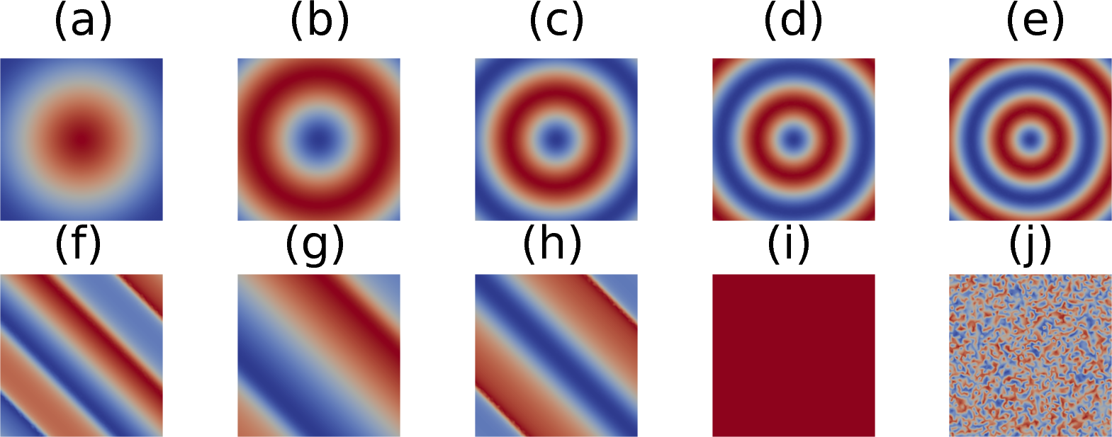
We compute the ground state phase diagram for two types of FeGe sample; square and triangular films of thickness, through dynamic simulations. Dynamic simulations are used in order that all discovered states are physically realisable. We explore the energy landscape of structures by changing the applied magnetic field, which is varied between and , and which is applied in the direction, into the plane of the system. In squares, we study films which have a side length of between and , and in triangles we use the broader range of side lengths between and . Initially, the magnetization of each point in the phase space is set to each configuration of a set of initial states; the definition of these states is the same as those used in the study of Beg et al. Beg et al. (2015) (see Supplementary Material). The set of initial states, which includes uniform magnetization, skyrmionic state profiles, helical profiles, and a random magnetization state (which is repeated three times) are shown in Fig. 1. This systematic exploration is done in order to capture as many equilibrium states as possible for each simulated system. In order to construct the ground state phase diagrams, we relax systems from these initial states under the LLG equation, until the system has settled into a local (or global) minima in the energy landscape. States are considered to be in equilibrium, and simulations are stopped, when the value of is less than a tolerance of 0.01 degrees per nanosecond, at which point the magnetization is no longer changing. We use a damping factor value of in order to achieve convergence to the final states quickly, by suppressing the precessional dynamics, which does not affect the final state. Once the dynamics have subsided according to the above criterion, we compute the total energy of these relaxed states. We identify the lowest energy state that we have found (from the set of simulations starting from different initial configurations) as the ground state for the given geometry and applied field value, which allows us to construct phase diagrams of the ground states. Higher energy states we consider to be metastable.
To perform the simulations, we use the finite-element micromagnetic simulator Finmag, developed at the University of Southampton. This uses the DOLFIN component of the finite-element solver FEniCS,Logg and Wells (2010) and integrators from the CVODE component of the SUNDIALS library.Hindmarsh et al. (2005)
III Results
III.1 Equilibrium States

A wide variety of equilibrium states (formed of both the ground and metastable states) are obtained from the simulations in the systems, and in Fig. 2, we show the regions in phase space where each state can form as an equilibrium state. The equilibrium states can be broadly classified into several groups.

- 1.
-
2.
Isolated Skyrmions These states, normally axially symmetric in disks, are distorted by the boundary of the confined geometry in both triangular and square systems. (Fig. 2 (ii))
-
3.
Helical States A large variety of rotational spin textures form metastable states in the studied systems. (Fig. 2 (iii))
-
4.
Target States Target states can be considered as an isolated skyrmion, with an additional radial half-helical rotation. (Fig. 2 (iv))
-
5.
Skyrmion Clusters Multiple clusters of skyrmions form metastable states in the geometries when strong fields are applied to the system, resulting in a smaller skyrmion radius. We find these as high-energy metastable states for larger system sizes and for high applied fields. (Fig. 3)

III.2 Ground States

The ground state phase diagrams (Figs. 4 and 5) show the lowest energy states identified for each geometry size for a given applied field. For the square systems we see a large region where isolated skyrmions form the lowest energy state for sample sizes as low as with an applied field of 350 mT. For larger sizes, the range of applied fields where skyrmions form the ground state increases, and at , we compute that the skyrmion is the ground state with no applied field. For all sample sizes studied, we see that applied fields of above result in nearly uniform magnetization. With no applied field, from to we see several types of helical states form the ground state. These results are qualitatively similar to those seen in disk systems, though in disks, skyrmions formed the ground state with no applied field for smaller systems than in squares, with observation at disks of diameter greater than . Beg et al. (2015)
In Fig. 5, the ground state phase diagram for the triangular systems is shown. In contrast to the square systems, we do not identify skyrmions as the ground state when no applied field is applied for any sized sample we investigated, which shows a strong indication that the shape of the boundary of the system plays a crucial role in the energetics of magnetic skyrmions in confined geometries. Skyrmion states do form the ground state for systems of side length when an applied field of between and is present. For systems of side length , we see a number of helical states form the ground state with no field. We note that between 40 and 50 nm, we see quasi-helical type states, though the lengths in these systems are below the helical length of FeGe.
The incomplete skyrmion states identified in the triangular geometry vary significantly depending on the size of the systems. Notably, tilting of the magnetization at the boundary of the sample due to the DM interaction causes the magnetization to point most strongly along the axis of the applied applied field, with the strongest alignment along the axes of symmetry in both the square and triangular states, which can be seen in the incomplete skyrmion images shown in Fig. 2 (i).
III.3 Proposed experimental study
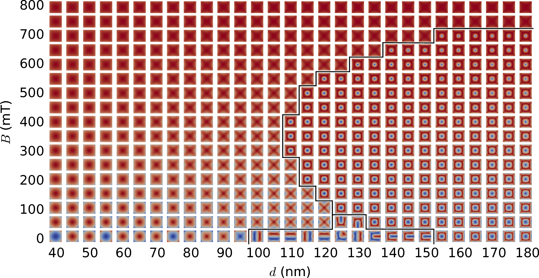
Of additional interest are states obtained from relaxing the systems from the uniform state. Experimentally, these states could be realised by initially applying a very strong applied field, to ensure that the magnetization of a sample is saturated, and then rapidly reducing the applied magnetic field. The states obtained from doing this in the square sample are shown in Fig. 6. We see four distinct bands of states, with incomplete skyrmions forming the bulk of the phase diagram. Skyrmion states are obtained in a narrow band, between and , with no applied field, and at larger sizes of system up to with an applied field of . For system sizes, from to with no applied field, we see target states, and at and above with no applied field, we identify helical states.
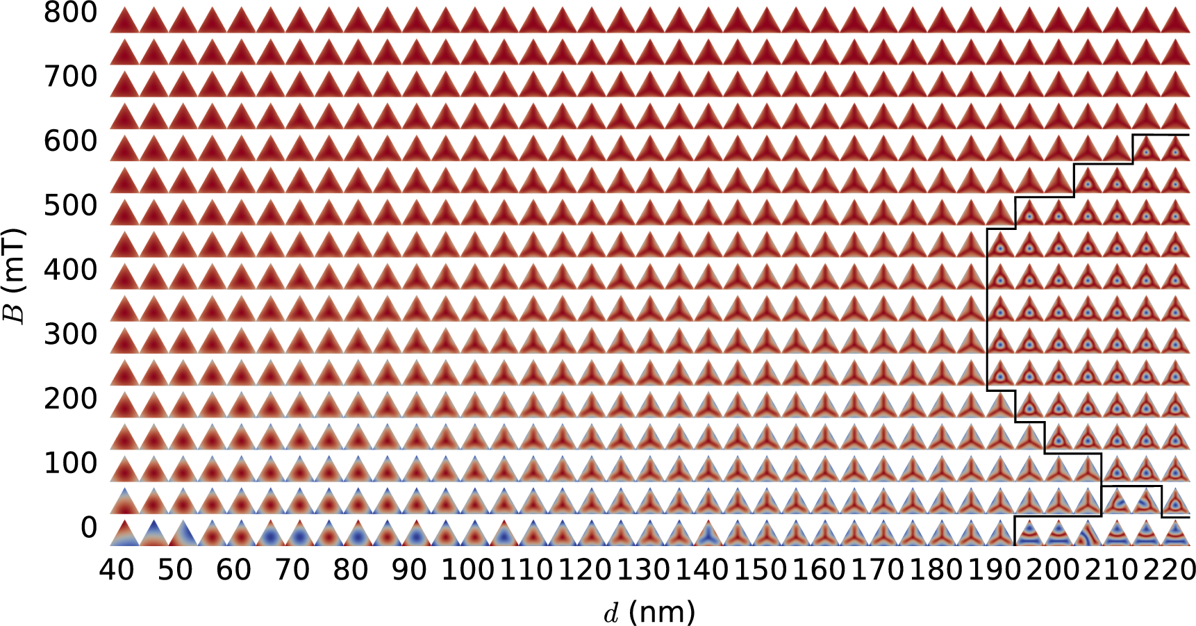
The corresponding uniform applied field results for triangular systems is shown in Fig. 7. Here, we see similar results; in the bulk of the phase diagram we see incomplete skyrmion states. For large systems of between and , when the field is reduced to a value between and , we see a small band of skyrmion states.
IV Summary
We show in this paper through micromagnetic simulations that in thick confined geometries of FeGe, skyrmions can form the lowest energy state. When there is no applied field, there exists a lower bound of side length between and , below which skyrmions do not form in square systems, and between and , a variety of helical type states form the ground state. In triangular systems, we see the incomplete skyrmion state forms the ground state in most of the phase space studied, and in large systems skyrmions form the ground state between fields of and .
We show over the same range of sizes and fields studied, a wide variety of states are in equilibrium, and we show where these states can be obtained. We present the states obtained from relaxing uniformly magnetised states from the saturated state, in both the square and triangular systems in order to motivate experimental work on FeGe confined geometries, and predict that skyrmion states should be experimentally accessible in both square and triangular systems. We also predict that in large square systems, target states should be accessible using the same procedure.
V Data Access Statement
All data supporting this study are openly available from the Zenodo repository at https://doi.org/10.5281/zenodo.1066791.
VI Acknowledgements
This work was financially supported by EPSRC Doctoral Training Centre grant (EP/L015382/1), EPSRC Doctoral Training Centre Grant EP/G03690X/1, OpenDreamKit Horizon 2020 European Research Infrastructure project (676541), and the EPSRC Programme grant on Skyrmionics (EP/N032128/1). D.C-O acknowledgees the financial support from CONICYT Chilean scholarship programme Becas Chile (72130061). We acknowledge the use of the University of Southampton IRIDIS High Performance Computing Facility. T.K. acknowledges financial support from the Gordon and Betty Moore Foundation. W.W. acknowledges the financial support of the National Natural Science Foundation of China (Grant No. 11604169).
VII References
References
- Bogdanov and Hubert (1994) A. Bogdanov and A. Hubert, Journal of Magnetism and Magnetic Materials 138, 255 (1994).
- Bogdanov and Hubert (1999) A. Bogdanov and A. Hubert, Journal of Magnetism and Magnetic Materials 195, 182 (1999).
- Rößler, Bogdanov, and Pfleiderer (2006) U. K. Rößler, A. N. Bogdanov, and C. Pfleiderer, Nature 442, 797 (2006).
- Muhlbauer et al. (2009) S. Muhlbauer, B. Binz, F. Jonietz, C. Pfleiderer, A. Rosch, A. Neubauer, R. Georgii, and P. Boni, Science 323, 915 (2009).
- Lee et al. (2009) M. Lee, W. Kang, Y. Onose, Y. Tokura, and N. P. Ong, Physical Review Letters 102, 1 (2009).
- Pfleiderer et al. (2009) C. Pfleiderer, A. Neubauer, S. Mühlbauer, F. Jonietz, M. Janoschek, S. Legl, R. Ritz, W. Münzer, C. Franz, P. G. Niklowitz, T. Keller, R. Georgii, P. Böni, B. Binz, A. Rosch, U. K. Rößler, and a. N. Bogdanov, Journal of Physics: Condensed Matter 21, 279801 (2009).
- Neubauer et al. (2009) A. Neubauer, C. Pfleiderer, B. Binz, A. Rosch, R. Ritz, P. G. Niklowitz, and P. Boni, Physical Review Letters 102, 1 (2009).
- Jonietz et al. (2010) F. Jonietz, S. Muhlbauer, C. Pfleiderer, A. Neubauer, W. Munzer, A. Bauer, T. Adams, R. Georgii, P. Boni, R. A. Duine, K. Everschor, M. Garst, and A. Rosch, Science 330, 1648 (2010).
- Zhang et al. (2016) S. L. Zhang, A. Bauer, D. M. Burn, P. Milde, E. Neuber, L. M. Eng, H. Berger, C. Pfleiderer, G. van der Laan, and T. Hesjedal, Nano Letters 16, 3285 (2016).
- Crépieux and Lacroix (1998) A. Crépieux and C. Lacroix, Journal of Magnetism and Magnetic Materials 182, 341 (1998).
- Heinze et al. (2011) S. Heinze, K. von Bergmann, M. Menzel, J. Brede, A. Kubetzka, R. Wiesendanger, G. Bihlmayer, and S. Blügel, Nature Physics 7, 713 (2011).
- Moreau-Luchaire et al. (2016) C. Moreau-Luchaire, C. Moutafis, N. Reyren, J. Sampaio, C. A. F. Vaz, N. Van Horne, K. Bouzehouane, K. Garcia, C. Deranlot, P. Warnicke, P. Wohlhüter, J.-M. George, M. Weigand, J. Raabe, V. Cros, and A. Fert, Nature Nanotechnology 11, 1 (2016).
- Richter (2007) H. J. Richter, Journal of Physics D: Applied Physics 40, R149 (2007).
- Fert, Cros, and Sampaio (2013) A. Fert, V. Cros, and J. Sampaio, Nature Nanotechnology 8, 152 (2013).
- Bessarab, Uzdin, and Jónsson (2015) P. F. Bessarab, V. M. Uzdin, and H. Jónsson, Computer Physics Communications 196, 335 (2015).
- Cortés-Ortuño et al. (2017) D. Cortés-Ortuño, W. Wang, M. Beg, R. A. Pepper, M.-A. Bisotti, R. Carey, M. Vousden, T. Kluyver, O. Hovorka, and H. Fangohr, Scientific Reports 7, 4060 (2017).
- Romming et al. (2013) N. Romming, C. Hanneken, M. Menzel, J. E. Bickel, B. Wolter, K. von Bergmann, A. Kubetzka, and R. Wiesendanger, Science 341, 636 (2013).
- Yu et al. (2012) X. Yu, N. Kanazawa, W. Zhang, T. Nagai, T. Hara, K. Kimoto, Y. Matsui, Y. Onose, and Y. Tokura, Nature Communications 3, 988 (2012).
- Zhang et al. (2015) X. Zhang, G. P. Zhao, H. Fangohr, J. P. Liu, W. X. Xia, J. Xia, and F. J. Morvan, Scientific Reports 5, 7643 (2015).
- Woo et al. (2016) S. Woo, K. Litzius, B. Krüger, M.-Y. Im, L. Caretta, K. Richter, M. Mann, A. Krone, R. M. Reeve, M. Weigand, P. Agrawal, I. Lemesh, M.-A. Mawass, P. Fischer, M. Kläui, and G. S. D. Beach, Nature Materials 15, 501 (2016).
- Krause and Wiesendanger (2016) S. Krause and R. Wiesendanger, Nature Materials 15, 493 (2016).
- Rohart and Thiaville (2013) S. Rohart and A. Thiaville, Physical Review B 88, 184422 (2013).
- Uzdin et al. (2017) V. M. Uzdin, M. N. Potkina, I. S. Lobanov, P. F. Bessarab, and H. Jónsson, Physica B: Condensed Matter (2017), 10.1016/j.physb.2017.09.040.
- Beg et al. (2015) M. Beg, R. Carey, W. Wang, D. Cortés-Ortuño, M. Vousden, M.-A. Bisotti, M. Albert, D. Chernyshenko, O. Hovorka, R. L. Stamps, and H. Fangohr, Scientific Reports 5, 17137 (2015).
- Zhao et al. (2016) X. Zhao, C. Jin, C. Wang, H. Du, J. Zang, M. Tian, R. Che, and Y. Zhang, Proceedings of the National Academy of Sciences 113, 4918 (2016).
- Zheng et al. (2017) F. Zheng, H. Li, S. Wang, D. Song, C. Jin, W. Wei, A. Kovács, J. Zang, M. Tian, Y. Zhang, H. Du, and R. E. Dunin-Borkowski, Physical Review Letters 119, 197205 (2017).
- Carey et al. (2016) R. Carey, M. Beg, M. Albert, M.-A. Bisotti, D. Cortés-Ortuño, M. Vousden, W. Wang, O. Hovorka, and H. Fangohr, Applied Physics Letters 109, 122401 (2016).
- Rybakov et al. (2016) F. N. Rybakov, A. B. Borisov, S. Blügel, and N. S. Kiselev, New Journal of Physics 18, 045002 (2016).
- Vousden et al. (2016) M. Vousden, M. Albert, M. Beg, M.-A. Bisotti, R. Carey, D. Chernyshenko, D. Cortés-Ortuño, W. Wang, O. Hovorka, C. H. Marrows, and H. Fangohr, Applied Physics Letters 108, 132406 (2016).
- Leonov et al. (2016) A. O. Leonov, Y. Togawa, T. L. Monchesky, A. N. Bogdanov, J. Kishine, Y. Kousaka, M. Miyagawa, T. Koyama, J. Akimitsu, T. Koyama, K. Harada, S. Mori, D. McGrouther, R. Lamb, M. Krajnak, S. McVitie, R. L. Stamps, and K. Inoue, Physical Review Letters 117, 1 (2016).
- Schneider et al. (2017) S. Schneider, D. Wolf, M. J. Stolt, S. Jin, D. Pohl, B. Rellinghaus, M. Schmidt, B. Büchner, S. T. B. Goennenwein, K. Nielsch, and A. Lubk, (2017), arXiv:1710.08322 .
- Fredkin and Koehler (1990) D. Fredkin and T. Koehler, IEEE Transactions on Magnetics 26, 415 (1990).
- Logg and Wells (2010) A. Logg and G. N. Wells, ACM Transactions on Mathematical Software (TOMS) 37, 2 (2010).
- Hindmarsh et al. (2005) A. C. Hindmarsh, P. N. Brown, K. E. Grant, S. L. Lee, R. Serban, D. E. Shumaker, and C. S. Woodward, ACM Transactions on Mathematical Software 31, 363 (2005).