reste-mail: oliver.rest@uni-muenster.de \thankstextalso1Also affiliated with Oak Ridge National Laboratory, Oak Ridge, TN 37831, USA
Calibration of high voltages at the ppm level by the difference of 83mKr conversion electron lines at the KATRIN experiment
Abstract
The neutrino mass experiment KATRIN requires a stability of 3 ppm for the retarding potential at -18.6 kV of the main spectrometer. To monitor the stability, two custom-made ultra-precise high-voltage dividers were developed and built in cooperation with the German national metrology institute Physikalisch-Technische Bundesanstalt (PTB). Until now, regular absolute calibration of the voltage dividers required bringing the equipment to the specialised metrology laboratory. Here we present a new method based on measuring the energy difference of two 83mKr conversion electron lines with the KATRIN setup, which was demonstrated during KATRIN’s commissioning measurements in July 2017. The measured scale factor of the high-voltage divider K35 is in agreement with the last PTB calibration four years ago. This result demonstrates the utility of the calibration method, as well as the long-term stability of the voltage divider.
Keywords:
voltage divider calibration KATRIN krypton-83m conversion electrons energy calibration1 Introduction
Precision high voltages (HV) at the ppm level are required for many applications in science, e.g. for defining the kinetic energy of electrons in an electron cooler at storage rings ullmann or for the precise determination of the energy of electrons in electrostatic retarding spectrometers or other analysers Dragoun2004 ; xpsbook ; PICARD1992345 .
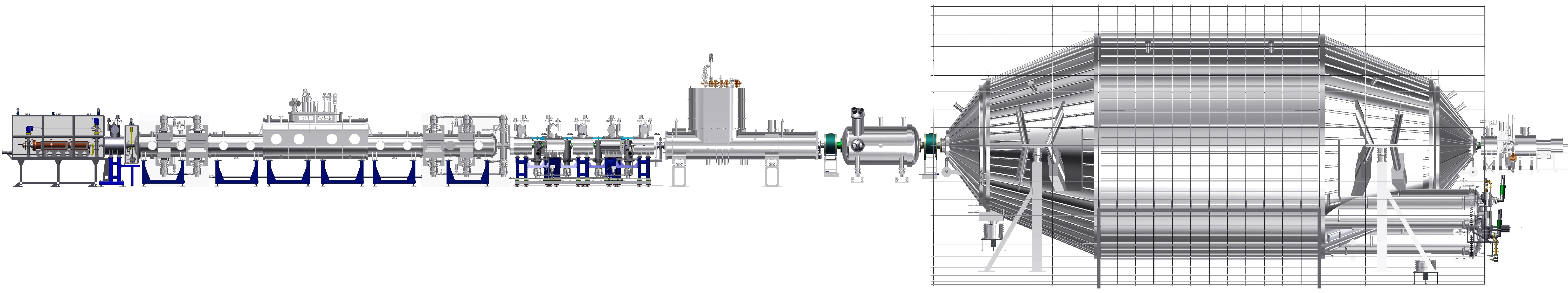
The KArlsruhe TRitium Neutrino (KATRIN) experiment designreport at the Karlsruhe Institute of Technology (KIT) (see fig.1) aims for a direct neutrino mass determination by a precise measurement of the tritium--decay spectrum near the endpoint. The expected sensitivity of the experiment is 0.2 eV/ at 90% C.L. Drexlin:2013lha . Currently the Mainz- Kraus:2004zw and Troitsk- Lobashev:2003kt ; Aseev:2011dq neutrino mass experiments set upper limits on the neutrino mass of 2 eV/c2.
In KATRIN, electrons are emitted from molecular tritium decaying in the windowless gaseous tritium source (WGTS) and are guided adiabatically by magnetic fields through the transport section. In this transport section, tritium is removed from the beamline by means of differential and cryogenic pumping. In the pre- and main spectrometers downstream from the transport section, the kinetic energy of the electrons is analysed. In order to reach the desired sensitivity, the spectrometers need to provide a large acceptance angle for the emitted -electrons and, in the case of the main spectrometer, a very good energy resolution as well. This is accomplished by operating the spectrometers as MAC-E filters PICARD1992345 , which are electrostatic retardation spectrometers (high energy filters) combined with magnetic adiabatic collimation to obtain large solid angle acceptance. Following the spectrometers, the focal-plane detector (FPD) AMSBAUGH201540 counts all electrons that have sufficient energy to pass both spectrometers. This FPD is a monolithic silicon -- diode with 148 pixels.
One key requirement of the experiment is the stability of the retarding potential (-18.6 kV) of the main spectrometer, which has to be maintained and monitored with a precision of 3 ppm (60 mV) over the measurement periods of two months. The knowledge of the absolute retarding potential would additionally allow a comparison of the tritium- endpoint with the nuclear mass difference of 3He and tritium 3H determined with Penning traps Streubel2014 ; VanDyck:1993zz ; Myers:2015lca .
Two independent approaches to monitor the high voltage are being pursued in order to ensure system redundancy. Firstly, since the HV cannot be measured directly with the required precision, a voltage divider is used to scale the retarding potential to V. The scaled retarding potential can then be determined with a commercial precision digital voltmeter (DVM). In this range, the voltage measurement can be calibrated against a 10 V reference, based on the Josephson effect, at the German national metrology institute Physikalisch-Technische Bundesanstalt (PTB). Since there is no commercial solution available with the required precision and stability, two custom-made ultra-precise high voltage dividers, named K35 Thummler:2009rz and K65 Bauer:2013pca , were developed and built in cooperation with the PTB.
An HV divider is characterised by its scale factor , which is defined as the ratio of input and output voltages. An absolute calibration with ppm-precision can usually be performed exclusively at metrology centres. The scale factor of the K35 was measured at PTB in 2013 to be
| (1) |
Secondly, the HV is compared to a natural standard given by mono-energetic conversion electrons from the decay of 83mKr. The parent isomer 83Rb is implanted into a solid-state source 1748-0221-8-03-P03009 at the BONIS facility in Bonn arenz_diss and used at the monitor spectrometer Erhard:2014ema . This third MAC-E filter is connected to the HV of the main spectrometer. Due to solid-state and surface effects, such as electron energy losses in the source material and drifts of the work function, absolute calibration of the HV at the required precision is not possible with such a source. However, relative changes over a measurement period of up to several months can be monitored slezak_diss .
In July 2017, a calibration and measurement campaign with gaseous 83mKr, injected into the WGTS from a 83mKr generating 83Rb source 1742-6596-888-1-012072 , was performed with the complete KATRIN beamline Drexlin:2013lha . With the well-known energies of mono-energetic conversion electron lines of this isotope, source properties of the WGTS and transmission properties of the spectrometers were investigated. Furthermore, the adiabatic transport of electrons from the source to the detector and the general alignment and functionalities of the complete system were tested kr_paper ; kr_paper_2 . This measurement campaign also provided the opportunity to calibrate the K35 HV divider to the ppm-level by comparing two conversion electron lines. A similar HV calibration was previously performed using a condensed 83mKr source at the former Mainz neutrino mass experiment thummler_diss . The main idea is to compare the kinetic energy of conversion electrons emitted from the same nuclear transition, but originating from different atomic shells. The systematic uncertainty of the nuclear transition energy cancels; the only remaining uncertainty, which is an order of magnitude lower, arises from the atomic binding energies. The measurements reported in thummler_diss were limited by systematic corrections of the order 100 meV. These corrections, which are not precisely known, account for the final state effects of the decaying nucleus in a submonolayer of 83mKr on a highly oriented pyrolytic graphite (HOPG) substrate. Gaseous sources overcome the disadvantages of a condensed or solid-state source.
In this work, the calibration of the HV divider K35 with gaseous 83mKr is presented. The next section gives an overview of the calibration concept and the determination of the scale factor of the divider using 83mKr conversion electron line measurements. Subsequently, the results of the calibration measurements performed at KATRIN are reported.
2 Calibration of a HV divider with 83mKr conversion electrons
83mKr decays via two cascaded transitions with gamma energies of 32151.6(5) eV and 9405.7(6) eV, respectively MCCUTCHAN2015201 . Both transitions decay dominantly by emission of conversion electrons instead of gamma radiation. In this work, only conversion electrons from the 32 keV transition are used.
The kinetic energy of a conversion electron from a 83mKr atom decaying freely in vacuum depends on the energy of the transition , the atomic binding energy , the nuclear recoil energies caused by the gamma111The nuclear recoil energy of the gamma transition enters, since the nuclear transition energy and the tabulated gamma energy differ by this nuclear recoil energy: . , and the conversion electron :
| (2) |
The binding energy depends on the atomic shell of the emitted electron. The values for used in this analysis were determined with X-ray and photoelectron spectroscopy measurements Dragoun2004 to be 14327.26(4) eV for the K- and 1679.21(3) eV for the L3-subshell. The nuclear recoil energy of the conversion electrons can be calculated to be 0.120 eV for the K- and 0.207 eV for the L3-subshell for the 32 keV transition, both with negligible uncertainty.
83mKr decays in the WGTS under ultra-high vacuum conditions. The conversion electrons are guided magnetically and adiabatically through the beamline to the main spectrometer, where an integrated spectrum is recorded by varying the retarding potential. With the HV divider K35 and a precision digital voltmeter (Fluke 8508A)222The DVM was calibrated with a PTB-calibrated 10 V reference device (Fluke 732A)., which measures the output voltage of the K35, the corresponding retarding energy for a particle of charge can be determined using
| (3) |
where e. The transmission condition for electrons to pass the main spectrometer is given by
| (4) |
Since the retarding voltage is applied between the Fermi energies of the source tube and the spectrometer electrode system, describes the correction for the difference between the work functions of the two materials. Due to the large diameter of the main spectrometer of 10 m and the wire electrode covering the inner surface Valerius:2010zz , the retarding potential across the analysing plane is not perfectly equal to the applied potential and shows a radial dependence. Therefore, a pixel-wise correction for the potential has been used. This correction amounts to about 2.25 V for the 40 innermost detector pixels with a r.m.s. value of less than 60 mV and scales nearly linearly in radial direction. The average difference of this correction over all these pixels amounts to 9 mV between the HV settings for the K-32 and the L3-32 measurement.
The so-called transmission edge is a special case where the kinetic energy of the electrons equals the right-hand side of equation 4. Using equations 2 and 4, the scale factor of the HV divider is then given as
| (5) |
with measured at the transmission edge. Following equation 5, the K35 could be calibrated by analysing just a single line position. However, the nuclear transition energy and the work function difference are not known to the desired ppm level. This limitation can be resolved using the energy difference of two conversion electron lines from the same gamma transition
| (6) |
so that and 333The work functions of the source and spectrometer should be constant on the time scale of the measurements. are eliminated from the equation444With a very different technique noertershaeuser2018 , collinear laser spectroscopy on Doppler-shifted ions, an absolute high voltage calibration has been reported recently. This novel method profits from eliminating systematics by performing two measurements at two different Doppler-shifts similarly to the method reported here.. Since K35 has a negligible voltage dependency of 0.03 ppm/kV Thummler:2009rz , we assume a constant scale factor for the HV settings of the K-32 and the L3-32 measurement. The differences of the binding and recoil energies
| (7) | |||
| (8) |
add up to
| (9) |
The potential correction has been determined for every FPD pixel by an electric field calculation with the simulation software Kassiopeia 1367-2630-19-5-053012 .
In order to determine the individual line energy positions, the observed integral spectrum was fitted with MINUIT refMINUIT . The fit function consists of a Lorentzian with free amplitude , width and the energy or , convolved with the transmission function of the main spectrometer:
| (13) |
and a constant background term Drexlin:2013lha . Here we used the abbreviation from equation 3. Relativistic corrections are included in equation 2 using the Lorentz factor of the electron. The width of the transmission function is calculated from the energy of the electrons and the ratio of the magnetic flux densities in the analysing plane ( mT) and that at the exit of the spectrometer ( T).
Equation 2 is derived assuming an isotropically emitting source. In the case that the source magnetic field ( T) is lower than the maximum magnetic field encountered by the electrons on their way to the detector, the maximum amplitude of the transmission function is limited by magnetic reflection of the electrons with emission angles that exceed a cut-off angle given by
| (14) |
The final fit function for the K-32 line is
| (15) |
where the modified transmission function contains three additional corrections: Firstly, the temperature of the 83mKr gas in the WGTS of 100 K leads to a thermal Gaussian broadening of the conversion line. Secondly, a high voltage ripple of the retarding potential was observed throughout the measurementskr_paper . The ripple had a nearly sinusoidal shape with a frequency of 50 Hz and an amplitude of 187 mV for the K-32 line and of 208 mV for the L3-32 line. The Gaussian broadening and the recorded ripple signal are convolved with the transmission function in the fit. Thirdly, the shape of the transmission function will be modified by synchrotron radiation losses555The synchrotron radiation affects the transversal energy (i.e. in the motion direction transversal of the magnetic field ) with the power loss , where is the relativistic factor and is the velocity. In the non-relativistic case, the power loss amounts to . Hence electrons emitted with high angles will be transmitted at lower retarding potentials, which results in a broadening of the transmission function., increasing its width by about 3 % (2 %) for the K-32 (L3-32) line.
3 Calibration results for the HV divider K35
During the KATRIN calibration and measurement phase in July 2017, the energy of all conversion electron lines of the gaseous 83mKr source were measured. The K-32 and L3-32 lines were used to calibrate the high-voltage divider K35 as described in section 2.
In this work, a combined analysis of the 40 innermost detector pixels (out of 148 pixels in total) was performed to obtain high statistics while avoiding increased systematic uncertainties at larger beam radii. Each detector pixel was treated with its corresponding potential correction . For illustration, the average of all K-32 and L3-32 conversion electron data of these 40 innermost detector pixels has been calculated and fitted, as shown in figure 2.
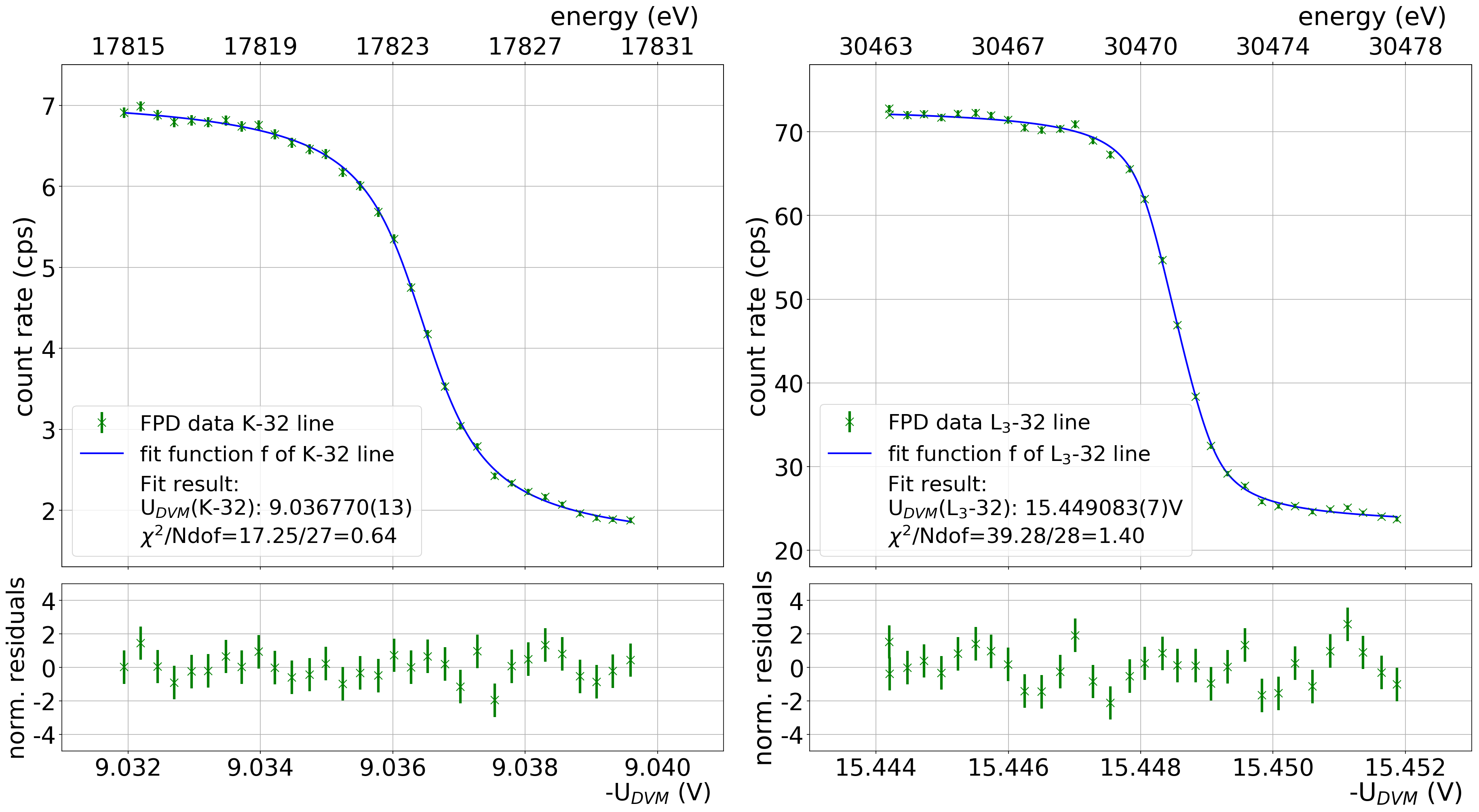
The good agreement between data and the fit model can be seen in the residuals as well as in the reduced values of the fits.
For the final result, we avoid averaging the pixel-dependent values by performing a combined 82-parameter fit666In this combined fit we used common fit parameters for line width and position (or , respectively) but with separate fit parameters for amplitude and background for each pixel (). of the data from the 40 innermost detector pixels, leading to the results shown in table 1.
| parameter | K-32 | L3-32 |
|---|---|---|
| U line position (V) | 9.036768(12) | 15.449083(9) |
| U line width (V) | 0.00135(4) | 0.00056(2) |
| /N | =0.98 | =1.05 |
The results from table 1 yield a voltage difference of
| (16) |
In the evaluation of the systematic uncertainties associated with this measurement, we considered a % variation of the high-voltage ripple amplitude and a % uncertainty of the synchrotron-radiation correction. The systematic uncertainty of the synchrotron radiation was estimated very conservatively because we did not apply a pixel-wise correction. The assumed meV uncertainty on the variation of for the different conversion electron lines results in an uncertainty of V for (equation 3).
In the voltage determination with the DVM, we applied a 0.5 ppm uncertainty on the read value and a 0.2 ppm uncertainty on the full range of the device. These effects yield uncertainties of 8.5 V (11.7 V) for the K-32 (L3-32) voltage reading, and 14.5 V for .
Since the term was already absorbed in the fitted data, the scale factor can be determined simply by dividing equation 9 by equation 16:
| (17) |
This result is in good agreement with the last calibration at PTB (eq. 1) within the uncertainties. With a four-year interval between the two calibrations, the relative deviation amounts to ppm. This means that the stability of the scale factor is on the ppm-level per year or better, assuming a constant drift. For a typical KATRIN measurement period, which is partitioned in two-month intervals, sub-ppm-stability can be assumed.
The uncertainty of 5 ppm of this new calibration method is dominated by the uncertainty of the difference of the atomic binding energies (relative uncertainty of 4 ppm). This could improve in the next years with more precise spectroscopic measurements or theoretical calculations. The combined relative statistical uncertainty of about 2 ppm can be improved by future measurements with higher statistics during calibration phases at KATRIN. The similarly large uncertainty of the voltage reading could be improved by measuring the two conversion lines in quick succession (20 min.) to mitigate the temporal drift effect of the device.
This measurement has also demonstrated that the relative stability of the HV divider is better than 3 ppm in a two-month interval, which significantly surpasses the design specifications.
4 Conclusion
In order to achieve the design sensitivity of 0.2 eV/ in the neutrino mass measurement, the retarding potential of the main spectrometer of the KATRIN experiment has to be monitored with a precision of 3 ppm over measurement intervals of two months. The retarding voltage is measured with two custom-made ultra-precise HV dividers that have to be calibrated regularly. In the past, such calibrations could only be performed at the special metrology laboratories. In this work, a new calibration method is presented, which based on the energy difference of two conversion electron lines produced by the decay of 83mKr. This method was previously applied with a condensed 83mKr source at the Mainz neutrino mass experiment, but surface and solid-state effects limited the attainable precision. Measurements with gaseous 83mKr at the KATRIN experiment are not affected by these effects, and allow the HV dividers to be calibrated with an uncertainty of 5 ppm. We have shown in this paper that such precision is achievable. The measured scale factor of the divider K35 is in agreement with earlier PTB calibrations. The results demonstrate the stability and reliability of the K35 HV divider to sub-ppm-levels over the two-month measurement intervals in KATRIN. This principle of determining the difference of two conversion electron lines with an electrostatic retardation spectrometer, e.g. of MAC-E-filter type, can be applied to other energy lines in other applications.
Acknowledgements.
We acknowledge the support of Helmholtz Association (HGF), Ministry for Education and Research BMBF (05A14VK2 and 05A17PM3), Helmholtz Alliance for Astroparticle Physics (HAP), and Helmholtz Young Investigator Group (VH-NG-1055) in Germany; Ministry of Education, Youth and Sport (CANAM-LM2011019, LTT18021), in cooperation with JINR Dubna (3+3 grants) in the Czech Republic; and the Department of Energy through grants DEFG02-97ER41020, DE-FG02-94ER40818, DE-SC0004036, DEFG02-97ER41033, DE-FG02-97ER41041, DE-AC02-05CH11231, and DE-SC0011091 in the United States.References
- (1) J. Ullmann, Z. Andelkovic, C. Brandau, A. Dax, W. Geithner, C. Geppert, C. Gorges, M. Hammen, V. Hannen, S. Kaufmann, K. König, Y.A. Litvinov, M. Lochmann, B. Maaß, J. Meisner, T. Murböck, R. Sánchez, M. Schmidt, S. Schmidt, M. Steck, T. Stöhlker, R.C. Thompson, C. Trageser, J. Vollbrecht, C. Weinheimer, W. Nörtershäuser, Nature Communications 8, 15484 EP (2017). doi:10.1038/ncomms15484
- (2) O. Dragoun, A. Špalek, F. Wuilleumier, Czechoslovak Journal of Physics 54(8), 833 (2004). doi:10.1023/B:CJOP.0000038591.13369.e1
- (3) P. van der Heide, XPS Instrumentation (John Wiley and Sons, Inc., 2011), pp. 27–60. doi:10.1002/9781118162897.ch3
- (4) A. Picard, H. Backe, H. Barth, J. Bonn, B. Degen, T. Edling, R. Haid, A. Hermanni, P. Leiderer, T. Loeken, A. Molz, R. Moore, A. Osipowicz, E. Otten, M. Przyrembel, M. Schrader, M. Steininger, C. Weinheimer, Nuclear Instruments and Methods in Physics Research Section B: Beam Interactions with Materials and Atoms 63(3), 345 (1992). doi:10.1016/0168-583X(92)95119-C
- (5) KATRIN collaboration, KATRIN design report. URL https://www.katrin.kit.edu/publikationen/DesignReport2004-12Jan2005.pdf
- (6) G. Drexlin, V. Hannen, S. Mertens, C. Weinheimer, Adv. High Energy Phys. 2013, 293986 (2013). doi:10.1155/2013/293986
- (7) C. Kraus, et al., Eur. Phys. J. C40, 447 (2005). doi:10.1140/epjc/s2005-02139-7
- (8) V.M. Lobashev, Nucl. Phys. A719, 153 (2003). doi:10.1016/S0375-9474(03)00985-0
- (9) V.N. Aseev, et al., Phys. Rev. D84, 112003 (2011). doi:10.1103/PhysRevD.84.112003
- (10) J. Amsbaugh, J. Barrett, A. Beglarian, T. Bergmann, H. Bichsel, L. Bodine, J. Bonn, N. Boyd, T. Burritt, Z. Chaoui, S. Chilingaryan, T. Corona, P. Doe, J. Dunmore, S. Enomoto, J. Formaggio, F. Fraenkle, D. Furse, H. Gemmeke, F. Glueck, F. Harms, G. Harper, J. Hartmann, M. Howe, A. Kaboth, J. Kelsey, M. Knauer, A. Kopmann, M. Leber, E. Martin, K. Middleman, A. Myers, N. Oblath, D. Parno, D. Peterson, L. Petzold, D. Phillips, P. Renschler, R. Robertson, J. Schwarz, M. Steidl, D. Tcherniakhovski, T. Thümmler, T.V. Wechel, B. VanDevender, S. Vöcking, B. Wall, K. Wierman, J. Wilkerson, S. Wuestling, Nuclear Instruments and Methods in Physics Research Section A: Accelerators, Spectrometers, Detectors and Associated Equipment 778, 40 (2015). doi:10.1016/j.nima.2014.12.116
- (11) S. Streubel, T. Eronen, H. M, J. Ketter, M. Schuh, R.S. Van Dyck Jr., K. Blaum, Appl. Phys. B114, 137 (2014). doi:10.1007/s00340-013-5669-x
- (12) R.S. Van Dyck, D.L. Farnham, P.B. Schwinberg, Phys. Rev. Lett. 70, 2888 (1993). doi:10.1103/PhysRevLett.70.2888
- (13) E.G. Myers, A. Wagner, H. Kracke, B.A. Wesson, Phys. Rev. Lett. 114(1), 013003 (2015). doi:10.1103/PhysRevLett.114.013003
- (14) T. Thümmler, R. Marx, C. Weinheimer, New J. Phys. 11, 103007 (2009). doi:10.1088/1367-2630/11/10/103007
- (15) S. Bauer, R. Berendes, F. Hochschulz, H.W. Ortjohann, S. Rosendahl, T. Thümmler, M. Schmidt, C. Weinheimer, JINST 8, P10026 (2013). doi:10.1088/1748-0221/8/10/P10026
- (16) M. Zboril, S. Bauer, M. Beck, J. Bonn, O. Dragoun, J. Jakubek, K. Johnston, A. Kovalik, E.W. Otten, K. Schloesser, M. Slezák, A. Spalek, T. Thuemmler, D. Venos, J. Zemlicka, C. Weinheimer, Journal of Instrumentation 8(03), P03009 (2013). URL http://stacks.iop.org/1748-0221/8/i=03/a=P03009
- (17) M. Arenz, doctoral thesis, University of Bonn (2017). URL http://hss.ulb.uni-bonn.de/2017/4930/4930.htm
- (18) M. Erhard, et al., JINST 9, P06022 (2014). doi:10.1088/1748-0221/9/06/P06022
- (19) M. Slezák, PhD thesis, Nuclear Physics Institute Czech Academy of Sciences (2015). URL http://www.katrin.kit.edu/publikationen/phd-Martin_Slezak.pdf
- (20) J. Sentkerestiová, D. Vénos, M. Slezák, Journal of Physics: Conference Series 888(1), 012072 (2017). URL http://stacks.iop.org/1742-6596/888/i=1/a=012072
- (21) M. Arenz, et al., (KATRIN collaboration), to be published (2018). URL https://arxiv.org/abs/1802.04167
- (22) M. Arenz, et al., (KATRIN collaboration), to be published (2018)
- (23) T. Thümmler, doctoral thesis, University of Münster (2007). URL https://miami.uni-muenster.de/Record/0e96c5e3-6f06-489e-a73f-5859fbe9cae7
- (24) E. McCutchan, Nuclear Data Sheets 125(Supplement C), 201 (2015). doi:10.1016/j.nds.2015.02.002
- (25) K. Valerius, Prog. Part. Nucl. Phys. 64, 291 (2010). doi:10.1016/j.ppnp.2009.12.032
- (26) J. Kraemer, K. Koenig, C. Geppert, P. Imgram, B. Maaß, J. Meisner, E.W. Otten, S. Passon, T. Ratajczyk, J. Ullmann, W. Noertershaeuser, Metrologia (2018). URL http://iopscience.iop.org/article/10.1088/1681-7575/aaabe0
- (27) D. Furse, S. Groh, N. Trost, M. Babutzka, J.P. Barrett, J. Behrens, N. Buzinsky, T. Corona, S. Enomoto, M. Erhard, J.A. Formaggio, F. Glueck, F. Harms, F. Heizmann, D. Hilk, W. Kaefer, M. Kleesiek, B. Leiber, S. Mertens, N.S. Oblath, P. Renschler, J. Schwarz, P.L. Slocum, N. Wandkowsky, K. Wierman, M. Zacher, New Journal of Physics 19(5), 053012 (2017). URL http://stacks.iop.org/1367-2630/19/i=5/a=053012
- (28) F. James, MINUIT - Function Minimization and Error Analysis. CERN Geneva (1994)