RHIP, a Radio-controlled High-Voltage Insulated Picoammeter and its usage in studying ion backflow in MPGD-based photon detectors
Abstract:
A picoammeter system has been developed and engineering. It consists in a current-voltage converter, based on an operational amplifier with very low input current, a high precision ADC, a radio controlled data acquisition unit and the computer-based control, visualization and storage. The precision is of the order of a tenth of picoampers and it can measure currents between electrodes at potentials up to 8 kV. The system is battery powered and a number of strategies have been implemented to limit the power consumption. The system is designed for multichannel applications, up to 256 parallel channels. The overall implementation is cost-effective to make the availability of multichannel setups easily affordable.
The design, implementation and performance of the picoammeter system are described in detail as well as a an application: the measurement of ion backflow in MPGD-based photon detectors.
1 Requirements
The project arose from the need of very low current measurements, with a precision of the order of a tenth of picoampere, between points laying at potentials of the order of a ten of kilovolts. Due to the high potentials involved, a good insulation between case and circuitry is needed, as well as an efficient insulation from noise. An automatic data read out and storage makes possible long measurement periods (hours or even days). The insulation requirements impose battery supplies and low power consumption for long measuring periods. A reasonably low cost is required in order to make multichannel systems easily affordable.
The above listed requirements implied not trivial choices during the development and prototyping of the apparatus.
2 The device and its implementation
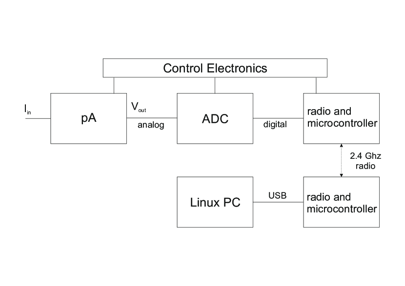
The picoammeter system can be split into five design blocks (Fig. 2): a current-voltage converter, based on an operational amplifier with very low input current; a high precision ADC; a radio controlled data acquisition unit; the control electronics; finally, the computer based overall control, visualization and storage.
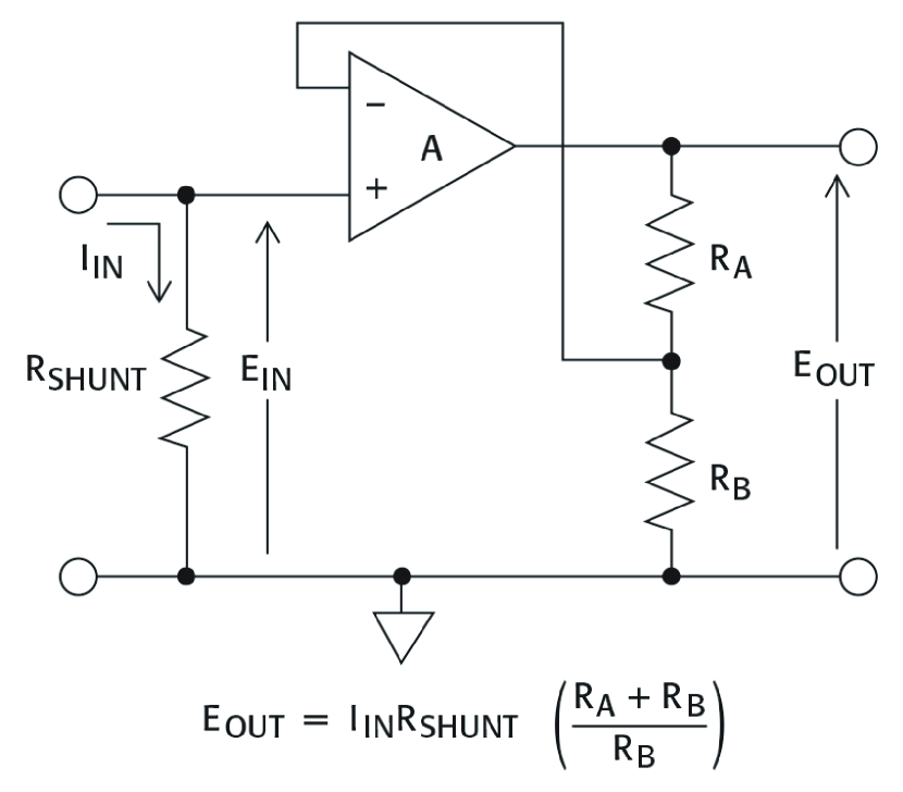
The current-voltage converter scheme is a classical one based on an OPerational Amplifier (OPA) with very low polarization current and feedback resistor (Fig. 2). The selected OPA is a monolithic one with ultra-low input bias current, realized in JFET technology with a typical input bias current of 40 fA, where the maximum value is 60 fA, at 25o C and supply voltage of 15 V. Input offset voltage and input voltage drift are 0.25 mV and 5 volt/degree respectively. The unity gain bandwidth is 1 MHz and the slew rate is 3 V/s. Great attention was payed to guarantee noise reduction, insulation of parts under high potential, separation of the analogue part (basically the converter) from the digital one (ADC, microcontroller, radio connection). This part is powered with NiMH PP3 8.2 V rechargeable batteries, compatible with more than a week continuos usage.
A digitization stage follows the current-voltage converter, based on an analog to digital converter: a 24 bits (at least 20 bits of effective resolution) ADC is used in order to obtained the required precision, equipped with SPI serial bus output. The ADC chip, after a sample conversion, goes in standby mode waiting for a serial readout request, a strategy resulting in a sensitive reduction of the power consumption.
A commercial microcontroller chip is used for the radio control: the selected one can control serial buses as well as communicate via radio with devices equipped with the same chip, in our application a computer via its USB interface. The current absorption of the chip is about 30 mA; the chip must be kept always active, because there is no option to wake it up from remote: it is the higher power consumption part of the picoammeter system. A dedicated high capacity lithium ions battery let this component work continuously for about a week.
The software to transmit and receive data via the PC USB port was elaborated from an available example, whereas, the software needed to interface the ADC via SPI is entirely original and optimized for the picoammeter needs.
The control electronics consists of two parts: monitoring the status of the batteries and switching on and off the power of the device, performed without touching the case, that lies at very high potential when connected. The battery status is controlled by low power comparators, that control low energy LED diodes. LEDs light up when battery voltages goes below a given threshold. Power is switched on/off by latching relays, that absorb energy only during status changes. The relay status change is induced by reed-relays activated by the proximity of a magnet, so there is no need of a contact with the picoammeter case [1]. Finally, a low current LED indicates the status of the device.
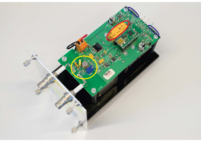
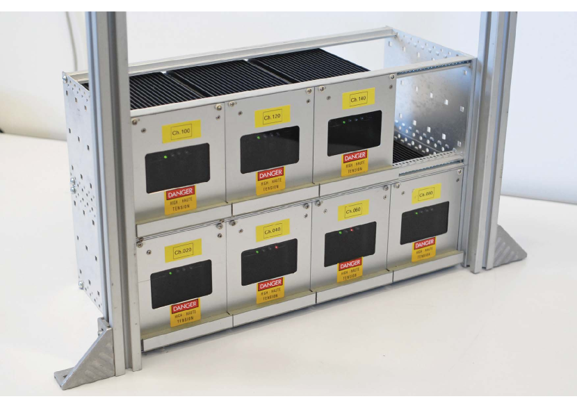
A set of seven picoammiter boards has been assembled and tested. One of the picoammiter boards is shown in Fig. 4: some relevant details described in the previous section are in evidence. A set of seven picoammiter channels have been mechanically arranged in an euro rack mini crate (Fig. 4).
The picoampermeters have been operated with different feedback resistors and the output value has been averaged over different number of samples. The typical measurement range is 2 nA and they exhibit precision of the order of 0.1 pA with a good thermal stability.
3 Data display and storage
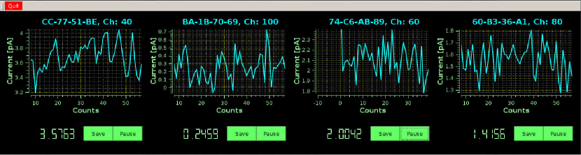
Visualization (Fig. 5) and storage of read out data is controlled by a program running on a Linux PC. The program communicates as master, via radio link, to the picoammeter ADC using one of its USB ports, acquiring converted voltage measurements. The radio controller has 256 radiofrequency channels, so theoretically a single PC can control up to 256 different picoammeters. The program is able to identify the connected devices at start up; alternatively, it is possible to specify the address of the devices to be contacted. In addition, the program can store data from one or more displayed channels to a text file, with the associated time stamp. The storage to a file can be activate/deactivate at any time. The program allows to define the time between two consecutive measurements and the number of samples to be averaged for a measurement; it also allows to set the timeout to deactivate a not responding channel or to pause/resume a picoammeter measurement.
4 Measurement of the ion backflow rate in a hybrid MPGD by the RHIP system
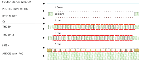
A novel single photon detector based on MPGD technologies [2] has been developed for the upgrade of the RICH-1 detector [3] of the COMPASS [4] experiment at CERN SPS. The new detector architecture consists in a hybrid MPGD combination (Fig. 6): two layers of THick GEMs (THGEM) [5], the first of which also acts as a reflective photocathode (its top face is coated with a CsI film) are coupled to a MicroMegas (MM) [6] on a pad segmented anode. The MM is resistive by an original implementation where the resistive MM is realized by discrete elements: HV is applied to the anode pads , each one protected by an individual resistor, while the signals are collected from a second set of pads, parallel to the first ones, embedded in the anode PCB where the signal is transfered by capacitively coupling. An important requirement is the limitation of the Ion BackFlow (IBF) rate to the CsI-coated photocathode: in fact, ion bombardment causes the reduction of the CsI quantum efficiency after an integrated charge of about 1 mC/cm2 [7]. The novel photon detector design takes into account this requirement and the architecture optimization has been obtained thanks to IBF measurement by the RHIP system.
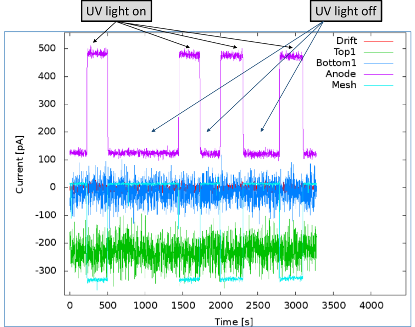
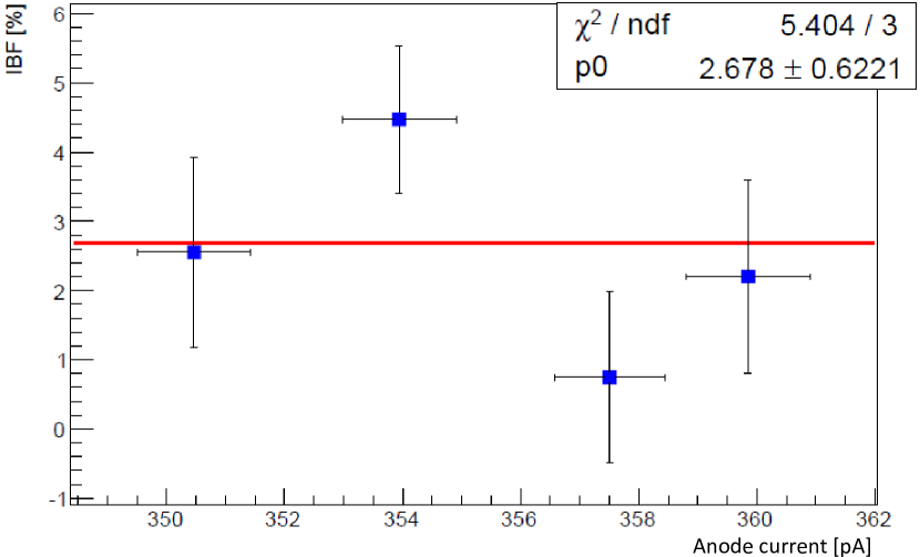
In a hybrid MPGD photon detector, IBF rate is measured by measuring the current of all the seven electrodes (drift wires, top and bottom faces of the two THGEMs, micromesh and anode pads) while illuminating the photocathode with UV light. A set of measurements performed alternating time intervals when light source is on to ones when it is off is shown in Fig. 8. The IBR rate in the optimized configuration is presented in Fig. 8 : IBR rate as low as 3% is obtained.
ACKNOWLEDGMENT
The activity is partially supported by the H2020 project AIDA2020 GA no. 654168.
References
- [1] The use of reed-relays activated by magnets was suggested by I. Konorov, private communication.
- [2] F. Tessatotto et al., ”The novel photon detectors based on MPGD technologies for the upgrade of COMPASS RICH-1”, these proceedings and references therein.
- [3] E. Albrecht et al., Nucl. Instr. and Meth. A 553 (2005) 215; P. Abbon et al. , Nucl. Instr. and Meth. A 587 (2008) 371; P. Abbon et al. , Nucl. Instr. and Meth. A 616 (2010) 21; P. Abbon et al. , Nucl. Instr. and Meth. A 631 (2011) 26.
- [4] P. Abbon et al. , Nucl. Instr. and Meth. A 577 (2007) 455; P. Abbon et al. , Nucl. Instr. and Meth. A 779 (2015) 69.
- [5] L. Periale et al., Nucl. Instr. and Meth. A 478 (2002) 377; P. Jeanneret, PhD thesis, Neuchatel University, 2001; P.S. Barbeau et al, IEEE NS-50 (2003) 1285; R. Chechik et al, Nucl. Instr. and Meth. A 535 (2004) 303.
- [6] Y. Giomataris et al., Nucl. Instr. and Meth. A 376 (1996) 29.
- [7] H. Hoedlmoser et al., Nucl. Instr. and Meth. A 574 (2007) 28.