Electrical transient laws in neuronal microdomains based on electro-diffusion
Abstract
The current-voltage (I-V) conversion characterizes the physiology of cellular microdomains and reflects cellular communication, excitability, and electrical transduction. Yet deriving such I-V laws remains a major challenge in most cellular microdomains due to their small sizes and the difficulty of accessing voltage with a high nanometer precision. We present here novel analytical relations derived for different numbers of ionic species inside a neuronal micro/nano-domains, such as dendritic spines. When a steady-state current is injected, we find a large deviation from the classical Ohm’s law, showing that the spine neck resistance is insuficent to characterize electrical properties. For a constricted spine neck, modeled by a hyperboloid, we obtain a new I-V law that illustrates the consequences of narrow passages on electrical conduction. Finally, during a fast current transient, the local voltage is modulated by the distance between activated voltage-gated channels. To conclude, electro-diffusion laws can now be used to interpret voltage distribution in neuronal microdomains.
Electro-diffusion in cellular nanodomains has recently regained interest due to the increase in fluorescent voltage dye indicators precision Hochbaum et al. (2014), development of nanopipettes Jayant et al. (2017) and in parallel the extension of the associated Poisson-Nernst-Planck theory to compute voltage. This theory was previously succesful to study ionic fluxes and gating of voltage-channels Bezanilla (2008), because at the nanometer scale, cylindrical symmetry of a channel reduces computations to a one-dimensional model for the electric field and charge densities in the channel pore Eisenberg (2007); Eisenberg et al. (1995). However, cellular microdomains involve in general two- and three-dimensional neuronal geometries Lee et al. (2013); Lopreore et al. (2008), which make the analysis of the PNP equations much more complicated than in the cylindrical geometry of a channel pore Qian and Sejnowski (1989). Nevertheless, the PNP theory is now used to study the current-voltage relation in several cellular compartments such as the synaptic cleft Sylantyev et al. (2013, 2008); Savtchenko et al. (2004), dendritic spines Cartailler et al. (2018) and many others Holcman and Yuste (2015). Indeed, the classical cable theory or simply the electrical resistance are insufficient to describe the electrical properties of a dendritic spine, which can be seen as a cellular micro-electrolyte. In general computing the I-V relation has remained controversial especially about the order of magnitude of an effective resistance, ranging from few to thousands of Mega Ohms Popovic et al. (2015); Acker et al. (2016); Kwon et al. (2017); Beaulieu-Laroche and Harnett (2017). Computing the I-V relation in the context of cellular physiology is relevant because any long lasting changes are a signature of a form of plastic changes, and having a precise relation would help clarifying synaptic plasticity, that underlies learning and memory.
In the absence of local electro-diffusion, we previously showed that geometrical features, such as curvature or narrow funnels can modulate the electrostatic properties of non-electroneurotral electrolytes Cartailler et al. (2017a) and could even generate local potential differences along the surface of a corrugated cylinder, between neighbording points of positive and negative curvature Cartailler et al. (2017b).
We report here novel I-V relations when a current is injected for various geometrical structures such as a dendritic spine modeled as a ball connected to a narrow neck. A constricted neck is modeled by a hyperboloid containing a narrow passage. The new relation we derived show significant deviation compared to the classical Ohm’s law. During a fast current transient, we further investigate how the local voltage is modulated and how it depends on the distance between the activated neighbording voltage-gated channels.
Poisson-Nernst-Planck (PNP) theory for electro-diffusion model.
The Poisson-Nernst-Planck (PNP) theory describe the coarse-grained dynamics of charged ions, accounting for the coupling between the ionic flow and electrostatic forces Eisenberg et al. (1995); Schuss et al. (2001); Mamonov et al. (2003); Abrashkin et al. (2007); Stinchcombe et al. (2016). For an electrolyte composed of two monovalent ions, the voltage and the concentration of positive and negative ions are described by
| (1) | |||||
where is the Faraday’s constant, the electrolyte permitivity, the thermal voltage and and are the diffusion coefficient for positive and negative charge respectively (see table 1 below). The present model can be extended to two cations K+, Na+ and one generic anions A-.
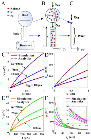
Voltage-Current relation for a dendritic spine. To find the I-V relation for a steady-state injected current made of positive charges, we use the reduction of the spine head geometry to a single point Cartailler et al. (2018) (Fig. 1A-B), because the voltage is constant (except in a boundary layer of the region where the current is injected) . We further approximate the narrow homogeneous cylindrical neck to a segment of length . To derive the I-V relation, we reduce equations 1, to a one dimension system with two species. The steady-state equations are
| (2) | |||||
where is the non-dimensionalized voltage. The boundary conditions are
| (3) | |||||
where the first term corresponds to the injected current at the head, is the radius of the neck and is the fixed concentration imposed for positive and negative species at the dendrite. A direct integration of eq. (2) using (3), leads to the Boltzmann distribution for negative charges in the one-dimensional segment. At this stage, we assume electro-neutrality at all spatial scale
| (4) |
Using (4) in (2), we obtain and the voltage
| (5) |
We conclude that the electrical resistance from eq. (5) is
| (6) |
In the limit , the leading order term in (6) reduces to Ohm’s law:
| (7) |
We validated expression 7 with repect to three-dimensional simulations of equation 1 (Fig. 1C-D and E-F). To conclude, Ohm’s law for electrolyte is valid only if the injected current is small or the section surface is large. In practice and thus the Ohm’s approximation (7) is not applicable and should be replaced by (6).
Voltage distribution with two positive specie Na+, K+.
Equations 2 can be used with three species K+, Na+ and anions A-, when a steady current composed of sodium ions is injected at one end, leading to
| (8) | |||||
with the boundary conditions:
| (9) | |||||
with . The no-flux boundary condition (9) implies that the concentrations and followed are Boltzmann distributions. Assuming the local electroneutrality at all spatial scale, we have
| (10) |
Using (10), we obtain an expression for the normalized potential
| (11) |
and the flux boundary condition in (9) leads to the expression for the concentration of :
| (12) |
The last descreasing term in expression (12) is an expression of the coupling between the potassium and the anionic concentration, when the injected current is due to the sodium ions only. Indeed, potassium ions are expeled due to the positive sodium ions. Surprizingly, the voltage is not affected by this coupling, indeed using , we reduced the system of equations (9) to two species and using (5), we get
| (13) |
and the effective resistance is given by
| (14) |
To conclude, equations (13) and (14) show that several monovalent ionic species do not affect neither the voltage nor the resistance of an electrolyte. However, the type of the injected ions influence the voltage distribution only through the diffusion coefficient of the injected specie (here ).
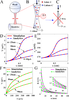
Steady-State PNP solutions in constricted neck. To account for a possible physical constriction in the neck of a spine or any other neuronal microdomains, containing positive and negative ions, we model this geometry as a hyperboloid of length with an elliptic base
| (15) |
(Fig. 2A), where the constriction has a surface . Following our previous anlaysis in one dimension 2, because the concentration of negative species depends only on the variable, assuming electroneutrality, we obtain that will also depends only on z. Thus the flux boundary condition 3 lead to,
| (16) | |||||
and we obtain
| (17) | |||||
leading to
Thus the voltage followed from the Boltzmann distribution (Electrical transient laws in neuronal microdomains based on electro-diffusion),
We conclude that the I-V relation is characterized by the current-dependent resistance
| (18) |
We confirm this new relation using numerical simulation (in dimension 3) in Fig. 2. To conclude, a single local constriction can increase drastically the effective resistance, which could be mediated by organelle located in the spine neck such as vesicle ot spine apparatus Korkotian and Segal (2011).
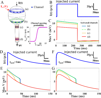
Transient properties.
We now study the properties when a transient step function for the current is generated in a cap around the north pole (with a radius ) of a dendritic spine. We solve numerically equations 1 (Fig. 3A). Except the cap, the rest of the boundary is reflecting for the potential and the ionic fluxes. At the dendrite, the concentration is maintained fixed. Interestingly, for a current with an ampltideu 50pA, we obtain a transient voltage with a maximum of 6mV (inside the spine). However, this transient is modified when voltage-gated channels organized in rings, can be activated (the activation curve is shown in Fig. 3A inset) when there are located inside the head. When channels are located at the entrance of the neck, they are activated with a delay of few hundreds of ms, but not at the base of the neck (fig. 3B-G). We conclude that voltage-gated channels located in the spine head can increase transiently the voltage amplitude generated by a synaptic current.
Conclusion.
To conclude, under the eletro-neutrality assumption at all scale, when a steady-state current is injected, we derived here novel I-V relation in a dendritic spine, which is a key microdomain underlying neuronal communication Yuste (2010). We further show how the I-V relation is affected by a neck constriction, which is often the case due to the presence of organelles such as a spine apparatus Korkotian and Segal (2011).
Injected a transient current revealed that the changes in the voltage can be sufficient to activate voltage-gated channels inside the spine head, but not located at the end of the spine neck. The main consequences of obtaining these laws is to show that local changes in the nano/microdomain geometry can modify the I-V relation, a part of nanophysiology that has often been neglected Savtchenko et al. (2017), and thus contribute to the modulation of synpatic plasticity.
| Parameter | Description | Value |
|---|---|---|
| Valence of ions | z=1 (for Na+ and K+) | |
| Diff. coeff. for charges | ||
| Diff. coeff. for charges | ||
| Tortuosity | ||
| charge concentration | mol/m3 Hille et al. (2001) | |
| charge concentration | mol/m3Hille et al. (2001) | |
| charge concentration | mol/m3Hille et al. (2001) | |
| charge concentration | mol/m3 Hille et al. (2001) | |
| Thermal voltage | V | |
| Dielectric constant | (water) | |
| Abs. Dielectric constant | F/m | |
| Faraday’s constant |
References
- Hochbaum et al. (2014) D. R. Hochbaum, Y. Zhao, S. L. Farhi, N. Klapoetke, C. A. Werley, V. Kapoor, P. Zou, J. M. Kralj, D. Maclaurin, N. Smedemark-Margulies, et al., Nature methods 11, 825 (2014).
- Jayant et al. (2017) K. Jayant, J. J. Hirtz, I. Jen-La Plante, D. M. Tsai, W. D. De Boer, A. Semonche, D. S. Peterka, J. S. Owen, O. Sahin, K. L. Shepard, et al., Nature nanotechnology 12, 335 (2017).
- Bezanilla (2008) F. Bezanilla, Nature reviews Molecular cell biology 9, 323 (2008).
- Eisenberg (2007) R. Eisenberg, Nature 447, 376 (2007).
- Eisenberg et al. (1995) R. Eisenberg, M. Kl/osek, and Z. Schuss, The Journal of chemical physics 102, 1767 (1995).
- Lee et al. (2013) P. Lee, E. A. Sobie, and C. S. Peskin, Journal of theoretical biology 338, 87 (2013).
- Lopreore et al. (2008) C. L. Lopreore, T. M. Bartol, J. S. Coggan, D. X. Keller, G. E. Sosinsky, M. H. Ellisman, and T. J. Sejnowski, Biophysical journal 95, 2624 (2008).
- Qian and Sejnowski (1989) N. Qian and T. Sejnowski, Biological Cybernetics 62, 1 (1989).
- Sylantyev et al. (2013) S. Sylantyev, L. P. Savtchenko, Y. Ermolyuk, P. Michaluk, and D. A. Rusakov, Neuron 77, 528 (2013).
- Sylantyev et al. (2008) S. Sylantyev, L. P. Savtchenko, Y.-P. Niu, A. I. Ivanov, T. P. Jensen, D. M. Kullmann, M.-Y. Xiao, and D. A. Rusakov, Science 319, 1845 (2008).
- Savtchenko et al. (2004) L. P. Savtchenko, N. Kulahin, S. M. Korogod, and D. A. Rusakov, Synapse 51, 270 (2004).
- Cartailler et al. (2018) J. Cartailler, T. Kwon, R. Yuste, and D. Holcman, Neuron (2018).
- Holcman and Yuste (2015) D. Holcman and R. Yuste, Nature Reviews Neuroscience 16, 685 (2015).
- Popovic et al. (2015) M. A. Popovic, N. Carnevale, B. Rozsa, and D. Zecevic, Nature communications 6 (2015).
- Acker et al. (2016) C. D. Acker, E. Hoyos, and L. M. Loew, Eneuro 3, ENEURO (2016).
- Kwon et al. (2017) T. Kwon, M. Sakamoto, D. S. Peterka, and R. Yuste, Cell reports 20, 1100 (2017).
- Beaulieu-Laroche and Harnett (2017) L. Beaulieu-Laroche and M. T. Harnett, Neuron (2017).
- Cartailler et al. (2017a) J. Cartailler, Z. Schuss, and D. Holcman, Physica D: Nonlinear Phenomena 339, 39 (2017a).
- Cartailler et al. (2017b) J. Cartailler, Z. Schuss, and D. Holcman, Scientific Reports 7, 11269 (2017b).
- Schuss et al. (2001) Z. Schuss, B. Nadler, and R. S. Eisenberg, Physical Review E 64, 036116 (2001).
- Mamonov et al. (2003) A. B. Mamonov, R. D. Coalson, A. Nitzan, and M. G. Kurnikova, Biophysical journal 84, 3646 (2003).
- Abrashkin et al. (2007) A. Abrashkin, D. Andelman, and H. Orland, Physical review letters 99, 077801 (2007).
- Stinchcombe et al. (2016) A. R. Stinchcombe, Y. Mori, and C. S. Peskin, Communications on Pure and Applied Mathematics 69, 2221 (2016).
- Korkotian and Segal (2011) E. Korkotian and M. Segal, The Journal of physiology 589, 5987 (2011).
- Yuste (2010) R. Yuste, Dendritic spines (MIT press, 2010).
- Savtchenko et al. (2017) L. P. Savtchenko, M. M. Poo, and D. A. Rusakov, Nature reviews. Neuroscience 18, 598 (2017).
- Hille et al. (2001) B. Hille et al., Ion channels of excitable membranes, Vol. 507 (Sinauer Sunderland, MA, 2001).