A metal-dielectric parabolic antenna to direct single photons
Abstract
Quantum emitters radiate light omni-directionally, making it hard to collect and use the generated photons.
Here we propose a 3D metal-dielectric parabolic antenna surrounding an individual quantum dot as a source of collimated single photons which can then be easily extracted and manipulated.
Our fabrication method relies on a single optically-induced polymerization step, once the selected emitter has been localized by confocal microscopy.
Compared to conventional nano-antennas, our geometry does not require near-field coupling and it is therefore very robust against misalignment issues, and minimally affected by absorption in the metal.
The parabolic antenna provides one of the largest reported experimental directivities () and the lowest beam divergences (), a broadband operation over all the visible and near-IR range, together with more than 96% extraction efficiency, offering a practical advantage for quantum technological applications.
![[Uncaptioned image]](/html/1803.11171/assets/fig0.png)
keywords:
optical antenna, nanophotonics, quantum dot, single photon emitter, directional emission, directivity, direct laser writingImperial] The Blackett Laboratory, Department of Physics, Imperial College London, London SW7 2AZ, United Kingdom Imperial] The Blackett Laboratory, Department of Physics, Imperial College London, London SW7 2AZ, United Kingdom Imperial] The Blackett Laboratory, Department of Physics, Imperial College London, London SW7 2AZ, United Kingdom \alsoaffiliation[LMU] Chair in Hybrid Nanosystems, Faculty of Physics, Ludwig-Maximilians-Universität München, 80799 München, Germany Imperial] The Blackett Laboratory, Department of Physics, Imperial College London, London SW7 2AZ, United Kingdom \phone+44 (0) 207 594 9577 \abbreviationsQD,AFM,FDTD,NA,APD
A single photon can be used for storage and long-distance transport of quantum information. Single photon sources have been realized in various solid state systems, such as single molecules 1, color centers in diamond 2, defects and color centers in 2D materials 3, 4, quantum dots 5. However, practical implementations of these sources for single-photon technologies are limited by their omni-directional radiation, which makes it hard to collect and use the generated photons.
Plasmonic nano-antennas 6, 7 have shown an elegant solution to this problem, as photons can be extracted by near-field coupling to metallic resonant elements, and radiated to the far field. Although a variety of plasmonic antenna design have been proposed, ranging from nanoaperture 8, optical patch antenna 9, v-shaped antennas 10 and Yagi-Uda antenna 11, they are all constrained by the large Ohmic losses in the metal which limit the single-photon extraction efficiency. Recently, dielectric antennas sustaining Mie resonances have attracted much interest as they feature low losses and a potential for quantum emitters engineering 12, 13. Nevertheless, both plasmonic and dielectric nano-antennas feature a limited directivity, which is constrained by their subwavelength size 14.
If the requirement of near-field coupling and sub-wavelength sizes is relaxed, a much larger directivity and extraction efficiency can be achieved, as shown for example for a planar dielectric-metal antenna 15, circular bullseye shaped antennas 16, or a silver coated nanopyramidal structure 17. Parabolic shaped nano and micro-structures have been demonstrated to act as unidirectional and broadband antennas at optical frequencies 18, 19.
For all the designs mentioned above, a common practical challenge lies in the precise emitter-antenna interfacing required for their operation. Several techniques for the deterministic positioning of an emitter near an antenna have been developed, such as multi-step lithography in combination with chemical functionalization 11, nano-manipulation by the tip of atomic force microscope 20, 21, near-field polymerization 22, and optical trapping 23. However, a controlled emitter-antenna interfacing remains rather a complex in-lab technology with poor reproducibility, and therefore an opposite approach, to bring an antenna over an emitter, has been pursued for example using in-situ far-field optical lithography 24, post-alignment electron-beam processing 25, 26, and a combination of in-situ electron-beam lithography and optical 3D laser writing 27.
In this Letter, we report a 3D hybrid metal-dielectric parabolic antenna to control the emission direction of an individual colloidal quantum dot. The design and fabrication circumvents the emitter-antenna alignment issues, because the antenna is made in-situ over a selected individual quantum dot. By optical Fourier imaging we observe a redirection of the emitted single photons into a beam in the direction normal to the sample plane with the divergence of , and over 20-fold increase of directivity comparatively to a quantum dot at air-glass interface. As a result, the single photon extraction rate is predicted to exceed 96% for and 60% for , while allowing for a broadband operation over the full visible and near-IR range.
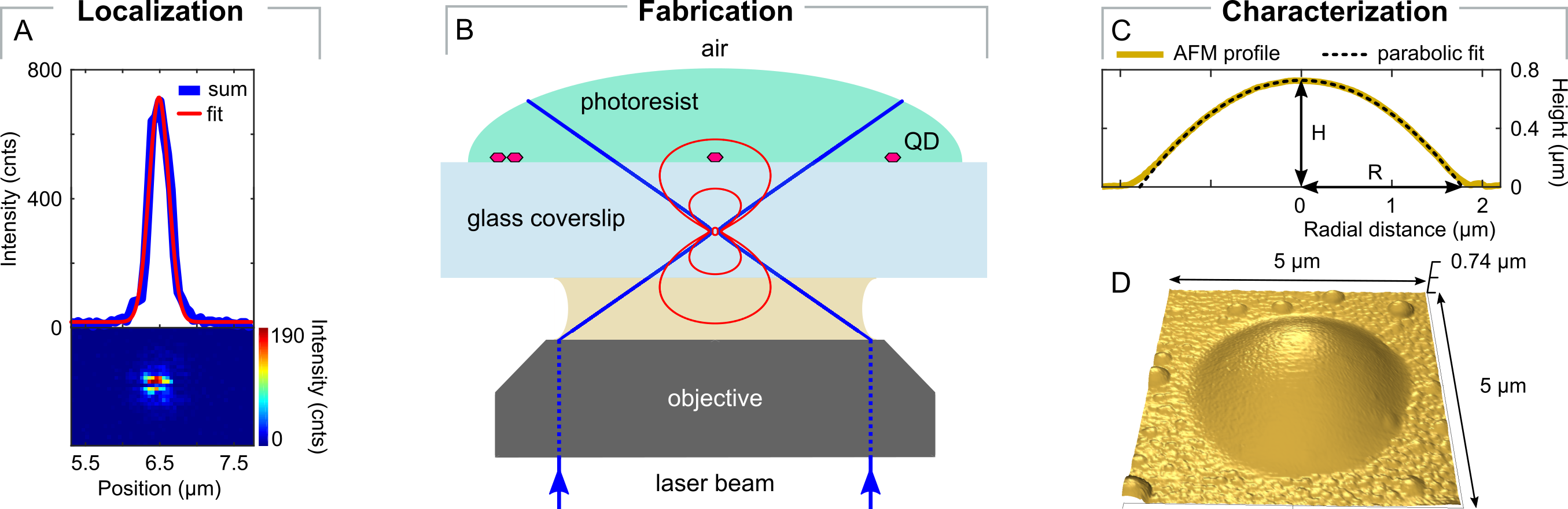
The proposed parabolic antenna is inspired by macroscopic parabolic reflectors, which project electromagnetic radiation from the focal point into a beam parallel to the parabola axis. We scale this concept to the micrometer size, and explore how far it can be applied to collimate the single-photon emission of a quantum emitter. The parabolic antenna is fabricated top-down on an individual emitter in a single-step of laser-induced polymerization. The fabrication scheme is the following: (1) a colloidal CdSeTe/ZnS quantum dot on a glass coverslip is localised by confocal microscopy, as in Fig 1A, with a typical sub 10 nm precision (which is the localization error of the centre of a diffraction limited spot 28), (2) a polymeric paraboloid is fabricated around it by one-photon polymerization of IPL-780 photoresist. This method exploits the parabolic shape of the top-most part of the iso-intensity profile of a focused Gaussian laser beam (see Fig. 1B, red closed lines) to expose the paraboloid in a single 70 ms laser illumination step at the exposure power of 2 W. By controlled defocussing of the writing beam, (see Fig. 1B), the paraboloid is aligned with the target quantum dot in its focal point. After washing the unexposed part of the photoresist, the resulting parabolic antenna is revealed. Atomic force microscopy (AFM) scan in Fig. 1D and its cross-section in Fig. 1C confirm that the polymerized paraboloid follows the target shape with a surface deviation from the parabolic shape of nm (see Supporting Information). The alignment of the antenna with the target quantum dot is confirmed post-fabrication by confocal imaging (see Supporting Information). Finally, (3) the polymeric antenna is covered with a thin 30-50 nm layer of gold to increase its reflectivity. The presence of the metal does not come with a substantal increase of photon losses, as the target quantum dot is about a wavelength (800 nm) away from the gold layer, too far for near-field coupling to the metallic shell.
The structural dimensions of the parabolic antenna can be controlled during the fabrication by two parameters, the exposure dose and the defocussing distance, which determine the size and curvature of the antenna. In order to achieve the collimated emission, the target quantum dot resting on a glass coverslip has to be in the focal point of the antenna, which is achieved when the paraboloid height and the radius of its aperture are related as (Fig. 1C). In that configuration the paraboloid focal length is . As a compromise between size and directivity, we have chosen the focal length to match the quantum dot emission maximum wavelength nm, thus the fabricated antenna has the geometrical parameters and , as shown in Fig. 1C (see also Supplementary Information).
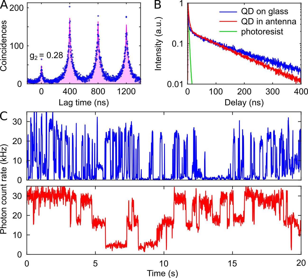
The parabolic antenna is expected to substantially leave the local density of optical states unaltered as it does not sustain optical resonances, with only a minor increase of Purcell factor of less than 30% revealed by numerical simulations (see Supplementary Information), related to the change of the quantum dot environment from an air-glass to an almost index-matched polymer-glass interface. Fluorescence dynamics studies in Fig. 2B shows that while the overall decay histogram of the target quantum dot before and after the fabrication is multi-exponential, the long decay component, attributed to neutral excitons, shortens from 159 ns to 132 ns when the emitter is covered with the photoresist. The short lifetime < 5 ns components arise from multi-exciton excitation and Auger recombination processes 29, 30, 31. As shown in Fig. 2A, before measuring the emission dynamics we test the fluorescence signal with an Hanbury-Brown and Twiss interferometer, to confirm antibunching of the emitted photons. For the specific case shown in Fig. 2A we report the second-order coherence . The photoresist is weakly luminescent with emission lifetime around 2.5 ns, which we report for completeness as the green decay histogram in Fig. 2B, and which contributes to the fast decay at short times. The complex blinking behavior shown in Fig. 2C prevents a precise assessment of the emission saturation values, but indicates that the maximum count rate is around 30 kCounts/s, which is preserved after the antenna fabrication. Fig. 2C indicates also that the off-times in the intensity time trace are slightly less probable in a quantum dot interfaced with the antenna, which we attribute to the protection of the target quantum dot from oxygen atmosphere when capped by the polymer, and the change in electrostatic environment 32, 33, 34. As a result, the total angular-integrated emission count rate averaged over a minute grows from 8.5 to 23.9 kCnts/s when the quantum dot is interfaced with the antenna.
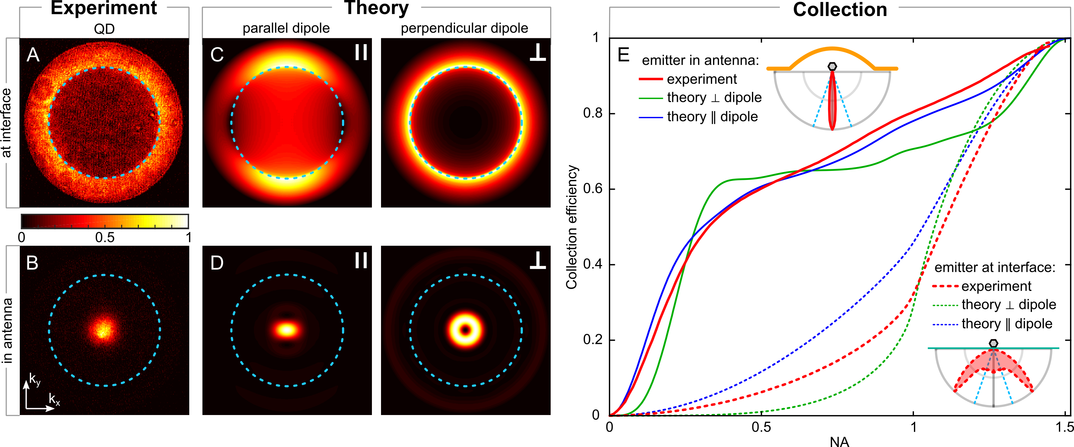
The antenna strongly affects the angular radiation of an emitter placed in the focal point of the parabolic antenna. This is evident when we compare the angular radiation patterns of an emitter before and after embedding it into the antenna. The experimental radiation pattern of a quantum dot at the air-glass interface (Fig. 3A) features a rotational symmetry pattern with most of the light outside the air-glass critical angle (blue dashed circle). This is consistent with the 2D degenerated transition dipole moment of a quantum dot, resulting into an emission pattern which is the sum of individual dipolar patterns 35. Instead, when the quantum dot is interfaced with the parabolic antenna, as presented in Fig. 3B, a sharp redirection of the emission occurs into a narrow beam normal to the sample plane with the half power beamwidth of . This beam is inside the light cone and can be collected without high NA optics due to its low divergence. These experimental results are well confirmed by numerical simulations (Fig. 3C-D). In the simulations shown in Fig. 3C-D, we can distinguish the contributions from the two dipole polarizations, parallel () and perpendicular () to the sample plane. Therefore, we can highlight that the parallel dipole is collimated around the normal direction with the emission divergence of , while the perpendicular dipole has a donut-like shape with a minimum in the normal direction and an annular emission very close to it. This is what one would expect from simple geometrical reasoning for a dipolar radiation.
The redirection of emission shown in Fig. 3B and D results in improved collection efficiency. We calculated the collection efficiency as a function of NA (Fig. 3E) by measuring the emission pattern with optics and selecting a section of it by radial integration of the experimental and theoretical angular radiation patterns (Fig. 3A-D). This is the relative collection efficiency which neither includes the imperfect detection efficiency of our setup, which we estimate to be around 5-10%, nor the minor angular-dependent detection efficiency. That is, photons originally emitted towards bottom half space are not affected by the parabolic antenna, and, therefore, cannot be collected with a low NA objective. For a quantitative comparison, we analyze emission from the emitter in opening towards a detector. We achieved experimentally a 10-fold increase of the collection efficiency with an objective of single photon emission from a quantum dot, namely from to .
The angular collimation reported in Fig. 3B and D in the - momentum space can be also described using the antenna directivity 36, 37. It is defined as a ratio of the radiation intensity in a given direction to the averaged radiation intensity in all directions. For the current design we achieved the directivity of . This value of directivity compares well to the prediction from numerical calculations for a dipole in the focal point of the parabolic antenna (Fig. 3D), which give and for the parallel and perpendicular dipole, respectively. This is to our knowledge one of the largest reported directivities, surpassing that of metal and dielectric antennas of similar size, which is in the range 5-25 38, 39, 18, 40.
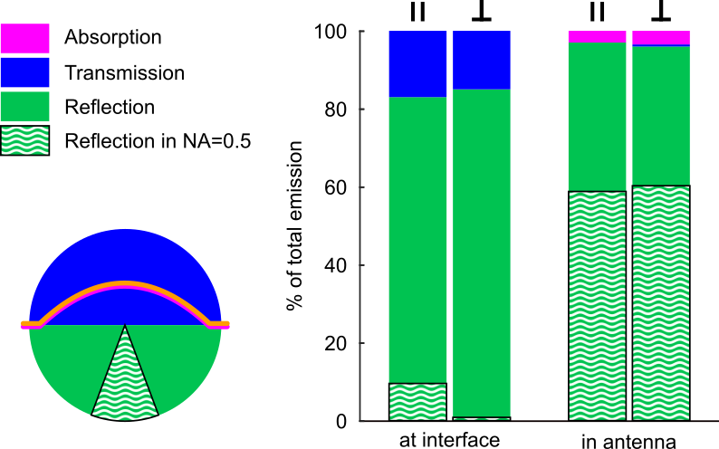
The parabolic antenna reflects the light which otherwise would have been lost into the upper half-space, and therefore increases the collection from the glass side. This can be quantified theoretically by calculating the photon extraction rate, and by analyzing how much of the emitted light is absorbed, transmitted and reflected by the quantum dot-antenna system. The numerical simulations plotted in Fig.4 show that in absence of the antenna, about % and % (depending on the dipole orientation) of the total emitted power goes to the lower half-space, i.e. in NA = 1.5, whereas the rest part of emission is lost in upper halfspace. Instead, if the emitter is interfaced with the parabolic antenna, % and % of the emitted photons can be extracted in the lower half-space, with a few percent absorption in the gold shell. This small increase in extraction efficiency for becomes a very large for , as this efficiency is drastically boosted by the directional radiation (wavy-white and green bars in Fig. 4). At the air-glass interface the power extraction rates in solid angle from a bare dipole are limited to and , while the antenna improves these values to and , providing over a 5- and 60-fold increase of the extraction rate, respectively. The simulations show that absorption in the gold layer accounts for less then of the total power loss (magenta bars in Fig. 4), while transmission through the parabolic reflector is completely suppressed (<).
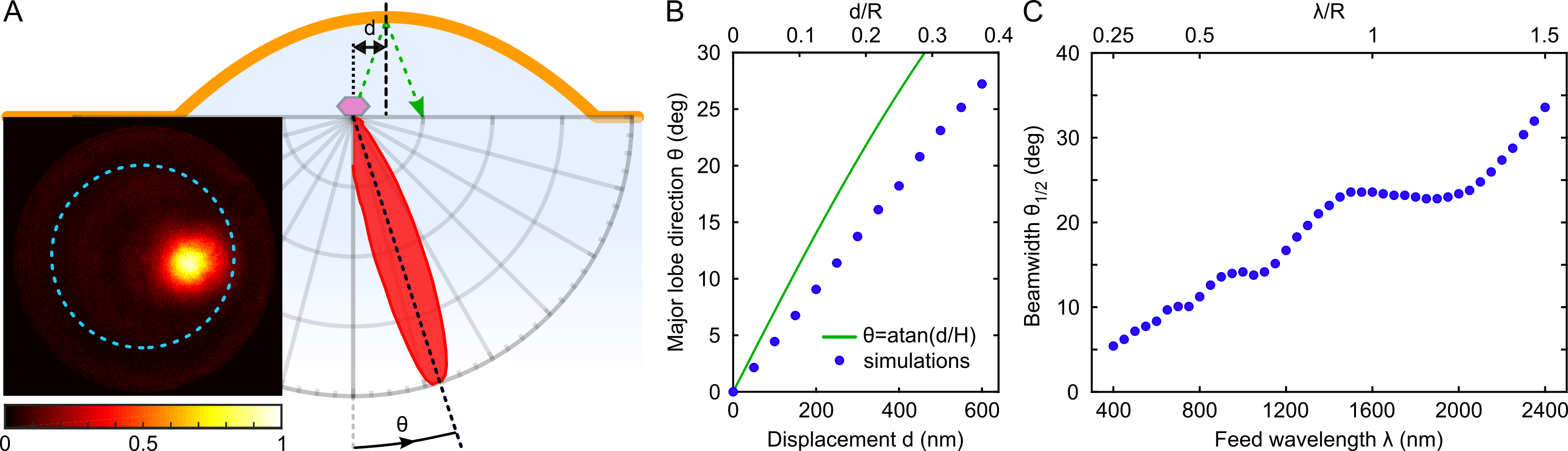
The antenna provides unidirectional single photon emission if the emitter is placed in its focal point. Radial and axial displacements of the emitter from the ideal position affect its radiation pattern by tilting the emerging beam and by widening the emission angle. We have observed that quantum dots placed below and above the focal plane have angular emission patterns with wider beamwidth and parasitic minor lobes, thus with a lower directivity (see Supporting Information). When an emitter is on the focal plane but displaced sideways by a distance from the axis of symmetry of the antenna, its emission remains directional, but it is tilted with respect to the normal to the sample plane as shown experimentally in Fig. 5A. The tilt can be explained in the approximation of geometrical and ray-optics considerations, that is the green ray shown in Fig. 5A which gives us a simple relation between the displacement and the direction of the major lobe (green curve in Fig. 5B). However, this approximation does not take into account the radiation pattern of the feed and the coma aberration introduced by the paraboloid shape of the antenna 41, so the actual tilt is smaller as confirmed by numerical simulations of angular radiation pattern of a parallel dipole displaced from the focal point (blue points in Fig. 5B). The experimental angular radiation pattern shown in Fig. 5A has the tilt of major lobe of to the normal, which is predicted to correspond to the displacement of about nm from the aperture center. Therefore, our geometry is very robust to radial misalignment of the target quantum dot with antenna, and it can be also used to direct single photons at specific angles up to . Given our sub 10 nm experimental precision in placing the antenna on the target quantum dot, the error in the direction of the major emission lobe is kept below .
The parabolic antenna does not sustain any optical resonances, therefore its response is broadband, with the only wavelength dependence in the parabola collimation power. The ability of the antenna to collimate light follows a simple Fourier relation with the antenna size: the larger antenna the lower the beam divergence. That is the beam divergence scales with the ratio 37. This prediction can be tested by numerical simulations of the beam divergence evolution versus the feed wavelength, as shown in Fig. 5C for the case of a parallel dipole. In Fig. 5C a linear dependence of on is visible, as expected, with an over-imposed oscillation which we attribute to the opening of parasitic side-lobes, which are especially strong at large ratios. Instead, for large parabolic antennas, i.e. small ratios, the oscillations are reduced and the general behavior follows the linear scaling of also found in macroscopic parabolic antennas. The dotted curve in Fig. 5C shows that the same parabolic antenna design can collimate radiation spanning the visible as well as telecom spectral range, with only a drop in the beam divergence.
The fabrication process is very versatile and can be adapted to various quantum emitters and antenna shapes, albeit limited to semi-planar geometries, sizes bigger than diffraction limit and below 10 micrometers due to laser power requirements. Most resists are also fluorescent which could impeded single-photon operation.
In conclusion, we have presented a 3D parabolic antenna fabricated with a simple photo-polymerization step capable of directing single photon emission into a narrow beam with divergence of . This corresponds to one of the highest directivities of single photon emission reported so far, and results in a more than 96% total and 60% in extraction efficiency. This can be very helpful for coupling into a fibre or for photon extraction in cryogenics conditions. The laser writing processing does not damage the emitters, and it can be flexibly applied to a wide range of single photon emitters, e.g. from defects in diamonds to individual molecules. The emitter-antenna hybrid delivers high-directional photons, with < absorption losses, and it is compatible with integration with nano-antennas and near-field photon engineering, offering a practical advantage for optical quantum technologies.
Methods. The experimental setup is a custom-built time-resolved confocal fluorescence microscope. It is based on the body of Nikon eclipse Ti inverted microscope. Samples were scanned with a 3D piezo stage (E-545.3CD PI nano). A large NA oil-immersion objective (Plan Apochromat 100x, NA=1.45) focused the laser radiation on a sample and collected the photoluminescence of a quantum dot. The collected photoluminescence signal was separated from the excitation laser by a dichroic mirror, and further filtered with a nm bandpass filter, and either sent to a grating spectrometer (IsoPlane SCT 320) with a CCD camera (PIXIS 400B eXcelon) or to avalanche photo diodes (APDs, SPCM-AQRH, Perkin Elmer).
A blue laser (LDH-D-C-440 Picoquant) at 442 nm with pulse width 64 ps and repetition frequency 2.5 MHz was used to excite quantum dots. Antibunching curves were measured using Hanbury-Brown and Twiss setup. It consists of two APDs which are connected to a time-correlated single photon counting module (TimeHarp 260, PicoQuant). The arrival times of photons on the detectors are collected into a histogram, producing the second order correlation function to verify the single photon emission. Decay histograms were collected by recording the time between the laser excitation pulse and the arrival time of a photon on a single APD. Angular radiation patterns of quantum dots were measured by imaging the back-focal (Fourier) plane on the CCD camera.
The theoretical model is based on the numerical solution of the Maxwell’s equations with a finite difference time domain (FDTD) method. The 3D FDTD simulations were performed using a commercial package (Lumerical).
The authors wish to thank Avi Braun and Sandro Mignuzzi for fruitful discussions. This research was funded by the Engineering and Physical Sciences Research Council (EPSRC EP/P033431, EP/M013812). S.M. acknowledges the Cromwell scholarship and S.A.M. the Lee-Lucas Chair in Physics.
Details on the design, fabrication and characterization of parabolic antennas can be found in the Supporting Information.
References
- Basché et al. 1992 Basché, T.; Moerner, W. E.; Orrit, M.; Talon, H. Phys. Rev. Lett. 1992, 69, 1516–1519
- Kurtsiefer et al. 2000 Kurtsiefer, C.; Mayer, S.; Zarda, P.; Weinfurter, H. Phys. Rev. Lett. 2000, 85, 290–293
- He et al. 2015 He, Y.-M.; Clark, G.; Schaibley, J. R.; He, Y.; Chen, M.-C.; Wei, Y.-J.; Ding, X.; Zhang, Q.; Yao, W.; Xu, X.; Lu, C.-Y.; Pan, J.-W. Nat. Nanotechnol. 2015, 10, 497–502
- Tran et al. 2015 Tran, T. T.; Bray, K.; Ford, M. J.; Toth, M.; Aharonovich, I. Nat. Nanotechnol. 2015, 11, 37–41
- Michler et al. 2000 Michler, P.; Imamoğlu, A.; Mason, M. D.; Carson, P. J.; Strouse, G. F.; Buratto, S. K. Nature 2000, 406, 968–970
- Novotny and van Hulst 2011 Novotny, L.; van Hulst, N. Nat. Photonics 2011, 5, 83–90
- Agio 2013 Agio, M. Optical antennas; Cambridge University Press: Cambridge, 2013
- Aouani et al. 2011 Aouani, H.; Mahboub, O.; Bonod, N.; Devaux, E.; Popov, E.; Rigneault, H.; Ebbesen, T. W.; Wenger, J. Nano Lett. 2011, 11, 637–644
- Belacel et al. 2013 Belacel, C.; Habert, B.; Bigourdan, F.; Marquier, F.; Hugonin, J.-P.; de Vasconcellos, S. M.; Lafosse, X.; Coolen, L.; Schwob, C.; Javaux, C.; Dubertret, B.; Greffet, J.-J.; Senellart, P.; Maitre, A. Nano Lett. 2013, 13, 1516–1521
- Vercruysse et al. 2014 Vercruysse, D.; Zheng, X.; Sonnefraud, Y.; Verellen, N.; Martino, G. D.; Lagae, L.; Vandenbosch, G. A. E.; Moshchalkov, V. V.; Maier, S. A.; Dorpe, P. V. ACS Nano 2014, 8, 8232–8241
- Curto et al. 2010 Curto, A. G.; Volpe, G.; Taminiau, T. H.; Kreuzer, M. P.; Quidant, R.; van Hulst, N. F. Science 2010, 329, 930–933
- Kuznetsov et al. 2016 Kuznetsov, A. I.; Miroshnichenko, A. E.; Brongersma, M. L.; Kivshar, Y. S.; Luk’yanchuk, B. Science 2016, 354, aag2472
- Cambiasso et al. 2017 Cambiasso, J.; Grinblat, G.; Li, Y.; Rakovich, A.; Cortés, E.; Maier, S. A. Nano Lett. 2017, 17, 1219–1225
- Koenderink 2017 Koenderink, A. F. ACS Photonics 2017, 4, 710–722
- Chu et al. 2014 Chu, X.-L.; Brenner, T. J. K.; Chen, X.-W.; Ghosh, Y.; Hollingsworth, J. A.; Sandoghdar, V.; Götzinger, S. Optica 2014, 1, 203
- Livneh et al. 2016 Livneh, N.; Harats, M. G.; Istrati, D.; Eisenberg, H. S.; Rapaport, R. Nano Lett. 2016, 16, 2527–2532
- Kim et al. 2016 Kim, S.; Gong, S.-H.; Cho, J.-H.; Cho, Y.-H. Nano Lett. 2016, 16, 6117–6123
- Schoen et al. 2012 Schoen, D. T.; Coenen, T.; de Abajo, F. J. G.; Brongersma, M. L.; Polman, A. Nano Lett. 2012, 13, 188–193
- Schell et al. 2014 Schell, A. W.; Neumer, T.; Shi, Q.; Kaschke, J.; Fischer, J.; Wegener, M.; Benson, O. Appl. Phys. Lett. 2014, 105, 231117
- Schietinger et al. 2009 Schietinger, S.; Barth, M.; Aichele, T.; Benson, O. Nano Lett. 2009, 9, 1694–1698
- Andersen et al. 2018 Andersen, S. K. H.; Bogdanov, S.; Makarova, O.; Xuan, Y.; Shalaginov, M. Y.; Boltasseva, A.; Bozhevolnyi, S. I.; Shalaev, V. M. ACS Photonics 2018,
- Volpe et al. 2012 Volpe, G.; Noack, M.; Aćimović, S. S.; Reinhardt, C.; Quidant, R. Nano Lett. 2012, 12, 4864–4868
- Geiselmann et al. 2014 Geiselmann, M.; Marty, R.; Renger, J.; de Abajo, F. J. G.; Quidant, R. Nano Lett. 2014, 14, 1520–1525
- Dousse et al. 2008 Dousse, A.; Lanco, L.; Suffczyński, J.; Semenova, E.; Miard, A.; Lemaître, A.; Sagnes, I.; Roblin, C.; Bloch, J.; Senellart, P. Phys. Rev. Lett. 2008, 101
- Sapienza et al. 2015 Sapienza, L.; Davanço, M.; Badolato, A.; Srinivasan, K. Nat. Commun. 2015, 6, 7833
- Schlehahn et al. 2016 Schlehahn, A.; Schmidt, R.; Hopfmann, C.; Schulze, J.-H.; Strittmatter, A.; Heindel, T.; Gantz, L.; Schmidgall, E. R.; Gershoni, D.; Reitzenstein, S. Appl. Phys. Lett. 2016, 108, 021104
- Fischbach et al. 2017 Fischbach, S.; Schlehahn, A.; Thoma, A.; Srocka, N.; Gissibl, T.; Ristok, S.; Thiele, S.; Kaganskiy, A.; Strittmatter, A.; Heindel, T.; Rodt, S.; Herkommer, A.; Giessen, H.; Reitzenstein, S. ACS Photonics 2017, 4, 1327–1332
- Balzarotti et al. 2016 Balzarotti, F.; Eilers, Y.; Gwosch, K. C.; Gynnå, A. H.; Westphal, V.; Stefani, F. D.; Elf, J.; Hell, S. W. Science 2016, 355, 606–612
- Sampat et al. 2015 Sampat, S.; Karan, N. S.; Guo, T.; Htoon, H.; Hollingsworth, J. A.; Malko, A. V. ACS Photonics 2015, 2, 1505–1512
- Galland et al. 2012 Galland, C.; Ghosh, Y.; Steinbrück, A.; Hollingsworth, J. A.; Htoon, H.; Klimov, V. I. Nat. Commun. 2012, 3, 908
- Malko et al. 2011 Malko, A. V.; Park, Y.-S.; Sampat, S.; Galland, C.; Vela, J.; Chen, Y.; Hollingsworth, J. A.; Klimov, V. I.; Htoon, H. Nano Lett. 2011, 11, 5213–5218
- Tang and Marcus 2005 Tang, J.; Marcus, R. A. J. Chem. Phys. 2005, 123, 054704
- Ko et al. 2010 Ko, H. C.; Yuan, C. T.; Lin, S. H.; Tang, J. Appl. Phys. Lett. 2010, 96, 012104
- Qin and Guyot-Sionnest 2012 Qin, W.; Guyot-Sionnest, P. ACS Nano 2012, 6, 9125–9132
- Koberling et al. 2003 Koberling, F.; Kolb, U.; Philipp, G.; Potapova, I.; Basch√©, T.; Mews, A. J. Phys. Chem. B 2003, 107, 7463–7471
- Novotny and Hecht 2012 Novotny, L.; Hecht, B. Principles of Nano-Optics; Cambridge University Press, 2012
- Balanis 2015 Balanis, C. A. Antenna Theory: Analysis and Design; Wiley, 2015
- Lee et al. 2011 Lee, K. G.; Chen, X. W.; Eghlidi, H.; Kukura, P.; Lettow, R.; Renn, A.; Sandoghdar, V.; Götzinger, S. Nat. Photonics 2011, 5, 166–169
- Aouani et al. 2011 Aouani, H.; Mahboub, O.; Devaux, E.; Rigneault, H.; Ebbesen, T. W.; Wenger, J. Nano Lett. 2011, 11, 2400–2406
- Peter et al. 2017 Peter, M.; Hildebrandt, A.; Schlickriede, C.; Gharib, K.; Zentgraf, T.; Förstner, J.; Linden, S. Nano Lett. 2017, 17, 4178–4183
- Born and Wolf 1999 Born, M.; Wolf, E. Principles of Optics: Electromagnetic Theory of Propagation, Interference and Diffraction of Light; Cambridge University Press, 1999