Fast Ignition Laser Fusion Using In-Situ Ion Acceleration With Pulsed CO2 Lasers
Abstract
Fast ignition is an alternative concept of laser fusion in which the task of compressing the fusion pellet to supersolid densities is accomplished by the conventional high energy nanosecond glass lasers and the task of igniting the compressed pellet is given to a high intensity, moderate energy pico second source which can set the pellet ablaze (with DT fusion reactions) by creating an adequate size hot spot in it. In this letter, we present a conceptual method by which energy from carbon dioxide () laser could be coupled to heat up ions produced in situ in the plasma, which in turn produces the required hot spot. An efficient conversion of energy into ion beam energy can thus give us the required source of energy for the fast ignition laser fusion. We demonstrate by using PIC (Particle - In - Cell) simulations that the use of several Kilo Tesla of an external magnetic field in the transverse direction in an inhomogeneous plasma where a cutoff is followed by a resonance can lead to coupling of laser energy to a lower hybrid ion plasma resonance. Then ions are accelerated efficiently () by the breaking of lower hybrid waves and thereby enabling the possibility of fast ignition by ions in a convenient fashion.
Fast ignition Tabak ; Kemp2014 is an alternative concept of laser fusion RevModPhys.46.325 ; Betti2016 in which the task of compressing the fusion pellet to super solid densities or more is accompolished by conventional high energy nanosecond glass lasers and the task of igniting the compressed pellet is given to a seperate high intensity, moderate energy pico second energy source which can set pellet ablaze (with DT fusion reactions) by creating an adequate size hot spot with ignition temperatures in it. Many alternatives have been considered for initiating the fast ignition heating process. The use of very high intensity micron laser picosecond pulses have not proven to be efficacious because the laser energy ends up in a relativistic electron beam at overdense compressed surface, which creates massive forward and return currents, current instabilities and filamentations of the beam on a rapid electron time scale Beg1997 ; Wilks1992 ; Kumar2017 ; Weibel ; Buneman1959 ; Bell1964 ; Roberts1967 ; Bret2009 ; Bret2010 ; EMHD ; cshukla . These instabilities lead to a divergence of the incident electron beam away from the central compressed target, thus preventing the formation of a hot spot in the interior. Other schemes considered, include mitigation of instabilities leading to turbulent magnetic fields with externally produced guiding magnetic fields ( in the range of ) Sheng_96 ; Knauer_2010 ; Yoneda_2012 ; Nagatomo2013 ; Fujioka2016 ; Matsuo2017 ; Sakata2017 , initiation using shock waves, using externally produced ion beams etc., but none so far have shown significantly improved results.00footnotetext: Predhiman Kaw is a deceased author.
The lasers are today the most efficient industrial lasers in the market and immediately come to mind where continuous wave (CW) and relatively long pulse applications are concerned Haberberger2010 ; Tochitsky2016 . They have not been as widely explored for the short pulse (sub-nano or pico second) applications. It is, therefore, not as widely known that chirped pulse amplification (CPA) techniques Strickland1985 have been applied to lasers. Right now , lasers with an energy content of about 100 joules are on anvil (after successful demonstration of , pulses). An energy range of about , pulses would be of direct interest to fast ignition fusion if a method could be found of delivering about of this energy to a hot spot in the compressed matter.
In this letter, we present a conceptual study followed up by the PIC simulations through OSIRIS-4.0 hemker ; Fonseca2002 ; osiris , of a method by which energy from the laser could be coupled through lower hybrid excitation to plasma for accelerating ions. These accelerated ions could, in turn, produce the required hot spot. If we consider ion heating for fast ignition of a fusion pellet, the requirements may be put as ion energy , beam current , beam period which is a beam pulse. An efficient conversion of energy into ion beam energy can thus give the required source of energy for fast ignition laser fusion. The detailed mechanism is derived below. The multiple advantages of using in situ accelerated ions as projectiles for delievering the energy to fusion fuel in the hot spot are: (1) Efficient coupling directly to fusion species, viz. background DT species ; (2) Ions being non relativistic and total current being much less than Alfven critical current for ions, magnetic fluctuations are expected to play negligible role in beam transport and beam stopping; (3) Classical collisional stopping of few MeV ions in dense core will be adequate; (4) Return currents, if any, will excite electrostatic ion acoustic modes leading to anomalous heating of the background plasma.
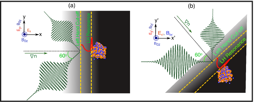
How do we utilize the laser for giving energy preferentially to ions? One point of departure from the past experience could be to use magnetized plasma modes for the interaction of the laser with the plasma. Now this is feasible since the external fields of the order Tesla have already been used in the laboratory Bailly-Grandvaux2018 . As the wavelength of this laser is times that of a glass laser, at a plasma density of , we have at a magnetic field of Tesla. Thus the magnetic field very strongly modifies the propagation physics of the laser beam through the plasma. In particular, if we choose X-mode of propagation for the entry of the laser into the plasma, the first cut-off (viz. right handed cutoff) and the first resonance (viz. the upper hybrid resonance) will not be encountered by the laser as it enters the plasma from the low density side. Similarly, the density for a corresponding resonance required for nonlinear Raman scattering Joshi1981 ; Rozmus1987 ; Mori1994 of perpendicularly propagating electron modes will also be excluded from plasma profile. It will thus become possible to use the second cut-off (the left handed cut-off) and the second resonance, namely the lower hybrid resonance, for the interaction of the intense laser light with the plasma. The laser propagation and the density profile has been illustrated in the schematic plot of Fig. 1(a). We use transverse magnetic field at the overdense laser plasma interface to immobilize the electrons due to strong magnetization and let ions as an unmagnetized species be accelerated by short wavelength (much shorter than ion Larmor radius) electrostatic waves such as lower hybrid resonance. In the linear regime, this suggests the utilization of the left handed cutoff and the lower hybrid resonance for the X-mode propagation Stix1960 ; Stix1965 ; Golant1972 ; P.BellanandM.Porkolab1975 ; Brambilla1976 .
Now, consider a propagation of electromagnetic waves in the X-mode configuration and the density gradient scale lengths to be long enough such that the resonances and cutoffs are well separated from each other and identifiable. It is well known that an electromagnetic wave propagating in the X-mode typically couples with the longitudinal modes at the upper and lower hybrid frequencies, giving interesting absorption phenomena Budden1962 ; White1974 . However, as stated earlier, the upper hybrid resonance has been ruled out in the present case due to the choice of the laser frequency in comparison to the electron cyclotron frequency. The dispersion relation for X-mode including ion response can be rewritten as
| (1) |
where,
| (2) | |||||
| (3) |
An examination of the resonances and cut offs show that for the choice of , the first cutoff that is encountered by the incoming laser beam is the left handed cut off given in Eq.(3). It has been shown by Budden Budden1962 and others that when an electromagnetic (EM) wave is incident from the low density side with cut off followed by resonance, the sum of the reflection and transmission coefficients does not add up to unity. This puzzle was solved by Budden Budden1962 when he showed by a mathematical analysis that the difference of energy is absorbed because of the coupling to electrostatic waves in the resonance region. In our situation, the left handed cut off is followed by the lower hybrid resonance. The absorption process of this resonance will thus put energy into lower hybrid waves. When the cut off and the resonance are close to each other, we can write the wave equation near these two points in the following form:
| (4) |
where it is assumed that is the direction of the density gradient (as shown in Fig. 1(a)), magnetic field is pointing in the plane and the dominant component of the laser electric field of the X-mode is in the direction. Eq.(4) shows a resonance at and the cut off at . The solution of Eq.(4) can be written in terms of the Whittaker functions. Carrying out the standard asymtotics to investigate the situations when the waves are incident on the cut off region from the low density side and get partially reflected and partially transmitted one finds that,
| (5) |
where, . we can note that squares of and do not add up to unity and that energy absorbed by the resonance is of the order of
| (6) |
This fractional absorption maximizes at and has a value . This of the incident laser energy is absorbed for the optimum case. Note that the above expression is based on the asymptotics and may only give an order of magnitude estimate and is not strictly accurate at the low values of . To determine , we need to find namely the distance between the reonance and the cut off. We restrict our attention to frequencies satisfying . The densities at the left handed cut off and the neighbouring lower hybrid resonance point are thus given by the following expressions respectively:
| (7) | |||
| (8) |
It may be noted from the expression of that is chosen below . Assuming a linear density profile between the cut off and the resonance point, we have
| (9) |
For a linear density profile between the cut off and the resonance points, we have .Thus the expression of is given as,
| (10) |
Note that the optimal parameter . We can then have the optimal scale length for density gradient length .
Next we make an estimate of the magnitude of ion acceleration during the lower hybrid resonance. Detailed calculations by Budden Budden1962 have shown that the energy absorbed in the above resonance absorption process is picked up by electrostatic lower hybrid waves which are dissipated either by collisions or by wave particle interactions. If the intensity of the wave is strong enough, this can lead to wave breaking and energy will be primarily picked up by the ions. Condition of wave breaking is approximately given by . This implies that the velocity excursion of the ion in the wave field exceeds the phase velocity of the wave so that even the cold background ions are brought into resonance with the waves accelerated by it. The condition may also be written in the form of , that is the kinetic energy picked up by the ions is of the order of the wave potential itself. We now estimate the magnitude electric field of the wave that will be excited in the cut off resonance process. Taking as the direction of propagation of the perturbed mode, where represents amplitude of the electric field.
| (11) |
where
| (12) | |||
| (13) | |||
| (14) |
We now show with the help of PIC simulations that the phenomena of lower hybrid excitation described above indeed occurs and is responsible for producing accelerated ions. For our simulation studies, we have chosen a system of electrons and ions where ions are assumed to be times heavier than electrons (i.e. where and denotes the rest mass of the ion and electron species). For electrons to be strongly magnetized and ions to remain unmagnetized, we have considered and (i.e. around the density layer where ion plasma frequency is in resonance with laser frequency) . Where and are the plasma and cyclotron frequencies respectively for species which corresponds to electrons and ions. Here is the magnitude of the electronic charge, represents the critical density of the plasma and is the magnitude of the applied external magnetic field. The external magnetic field is transverse to the density gradient, i.e. . The laser wave vector has a small component parallel to the external magnetic field. The laser electric field has been chosen to fall obliquely at an angle of with normal to the plasma density surface so as to have as finite. These conditions are required for the excitation of lower hybrid wave in the system. In order to accommodate an obliquely falling laser pulse on constant density surfaces in simulations, we have oriented the simulation box at an angle of as shown in Fig. 1(b). In the new system, we have the laser propagation directed along . The new coordinate axes have been represented by and they are related to the old system by the transformation:
The numerical experiment is performed by using particle-in-cell (PIC) code OSIRIS-4.0 hemker ; Fonseca2002 ; osiris . The rectangular simulation box is in -direction (the laser-propagation direction) and in -direction. The oblique target is composed of electron-ion plasma having density profile linearly increasing from to where is . The density has linear profile which can be expressed in a mathematical form as, . A p-polarized plane short pulse laser, having a wavelength of , is launched from the left boundary. It strikes the plasma target with an incident angle of . The peak intensities of with a rise and fall time of each has been chosen. The grid size is in both direction with cells per electron skin depth () and particles per cell for each species. The charges are weighted according to the initial local density. The boundary conditions for the electromagnetic fields and particles are absorbing in both and direction. The time step satisfying the Courant condition is . A uniform external magnetic field of kilo-Tesla is applied to strongly magnetize the electrons of the plasma along direction.
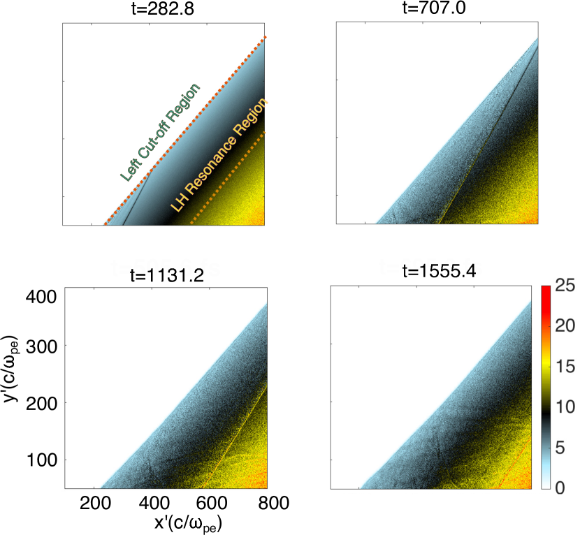
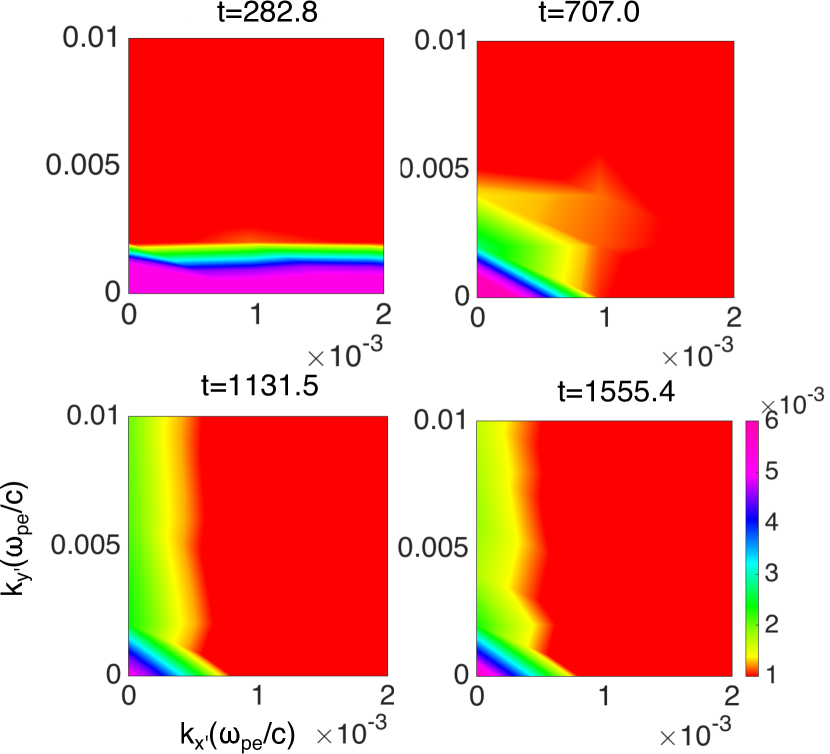
It is shown in Fig. 2 that the mode travels well beyond the lower hybrid resonance point which is around the line of density at . The value of at this point and matches well with the analytically calculated value from Eq.(11) which turns out to be . This is a clear indication of lower hybrid resonance. The electric field energy spectra have been shown in Fig. (3) at various times. It should be noted that the spectra vs. plane remains predominantly confined to finite (the laser propagation wave vector) at early times. However, at the time of mode conversion , power in finite starts acquiring power.
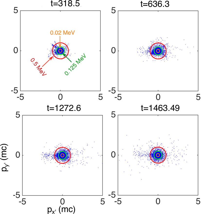
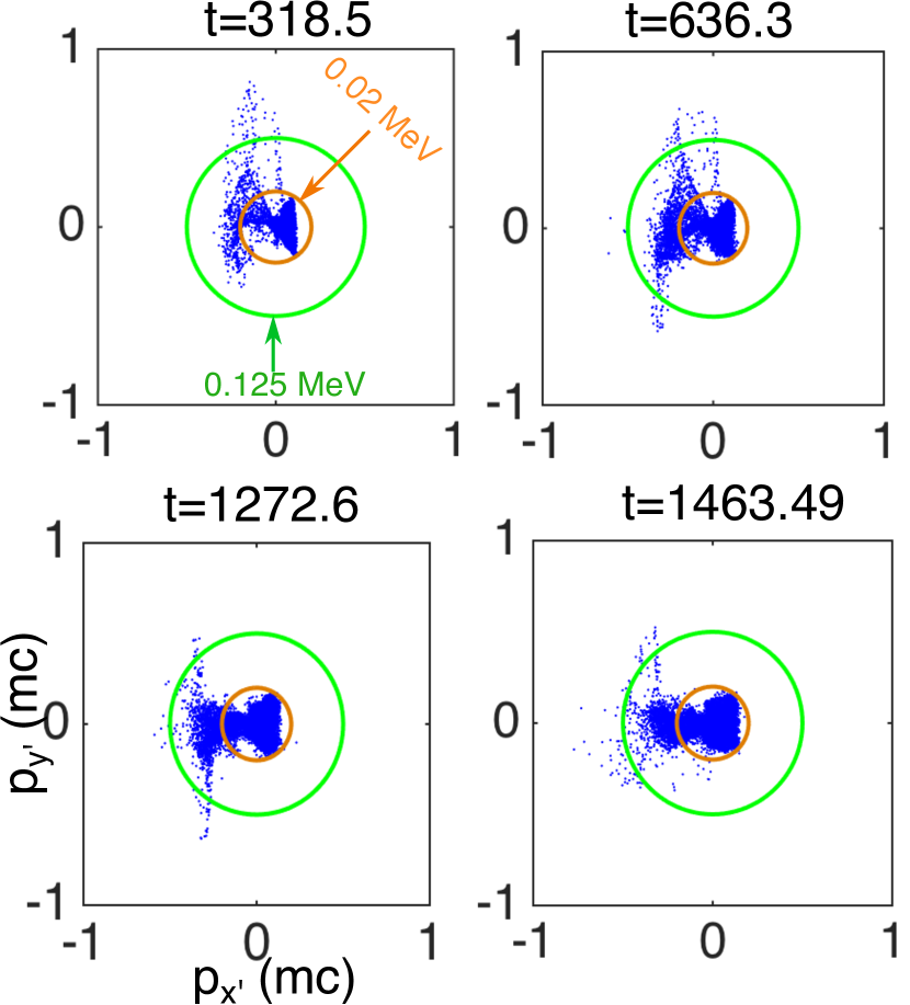
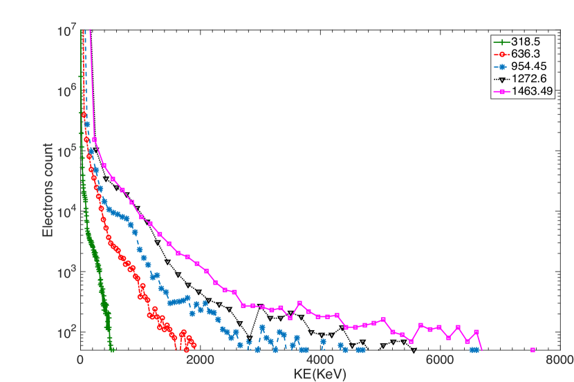
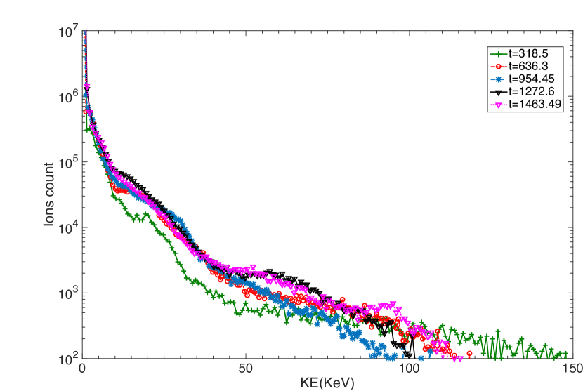
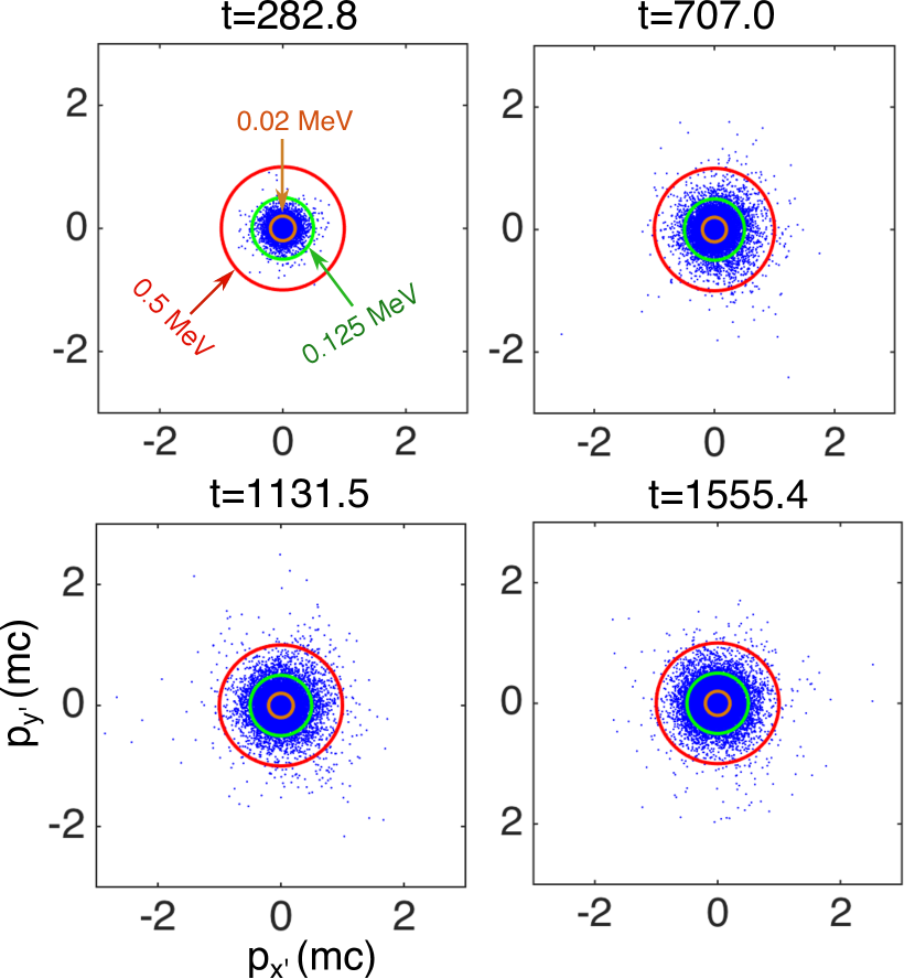
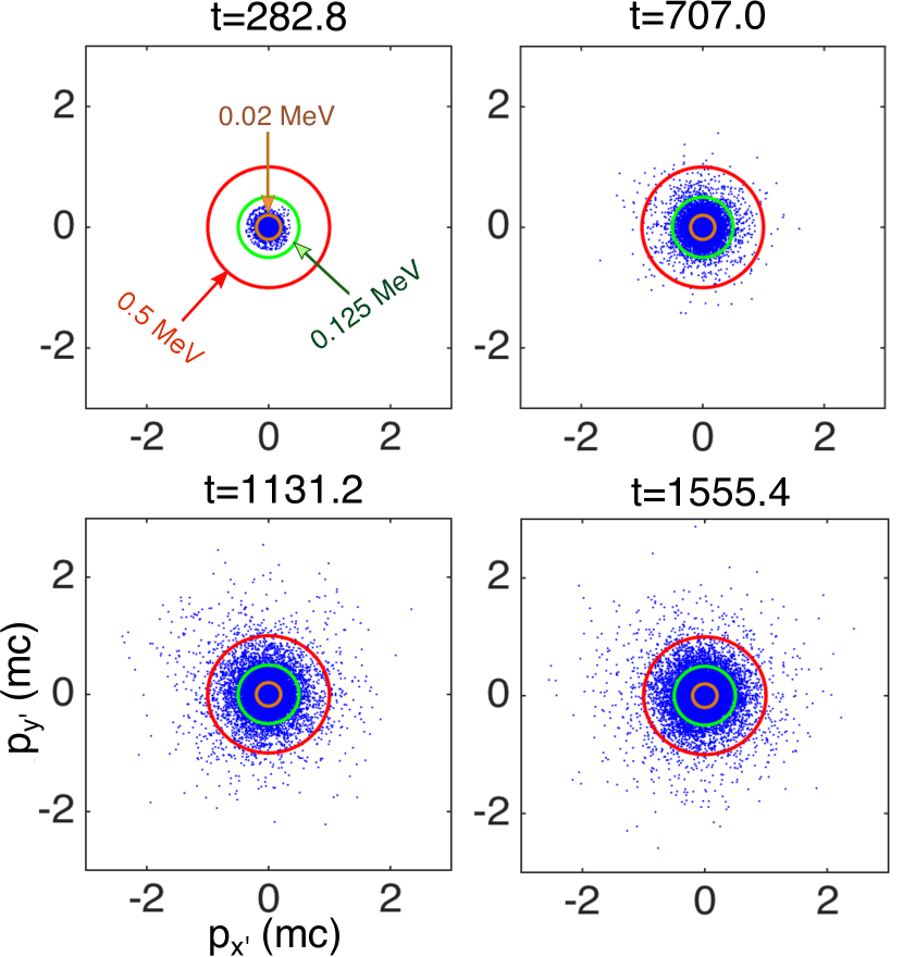
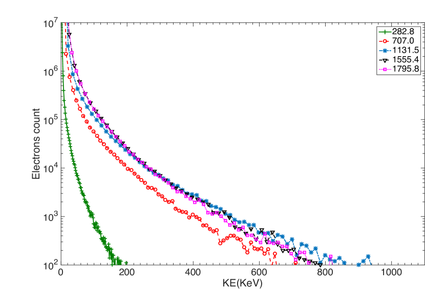
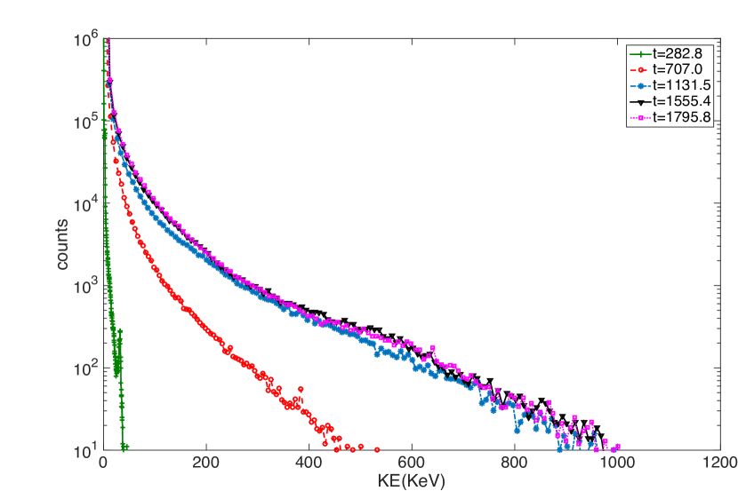
We have also provided a comparison of electron and ion energy gain in the presence and absence of the external magnetic fields. A comparison of Fig(4) and Fig(5) wherein the electron and ion distribution in the vs. with no external magnetic field shows that the energy acquired by the ions is quite small. The electron and ion counts for this case, plotted in Fig.(6) and Fig. (7) respectively, show that while electrons gain energy of the order of , the ion energy in this case is relatively small (). However, when the simulations are carried out in the presence of the external magnetic field, the energy acquired by electrons has been reduced to (Fig. (8)) and the gain in ion energy is higher as expected by the lower hybrid resonance heating mechanism shown in Fig. (9). Both species (electrons and ions) are accelerated up to (Fig. (10-11)). The approximate equipartition of electron and ion energies is also indicative of the lower hybrid resonance process. From the simulations, it is also evident that the factor which satisfies the breaking condition of the lower hybrid wave (i.e. ; where is the wavenumber of the mode, is the maximum electric field strength of the mode) near resonance region.
We have thus demonstrated the possibility of using lower hybrid resonance condition of lasers in the presence of external magnetic field for the in situ acceleration of plasma ions. When pulsed CPA based high power lasers have become available and the magnetic field of the order of Kilo Tesla have been created in the laboratory recently, the mechanism of ion acceleration proposed in our work is ideally suited for experimentation.
References
- (1) M. Tabak, J. Hammer, M. E. Glinsky, W. L. Kruer, S. C. Wilks, J. Woodworth, E. M. Campbell, M. D. Perry, and R. J. Mason, “Ignition and high gain with ultrapowerful lasers*,” Physics of Plasmas, vol. 1, no. 5, pp. 1626–1634, 1994.
- (2) A. J. Kemp, F. Fiuza, A. Debayle, T. Johzaki, W. B. Mori, P. K. Patel, Y. Sentoku, and L. O. Silva, “Laser-plasma interactions for fast ignition,” Nuclear Fusion, vol. 54, no. 5, 2014.
- (3) K. A. Brueckner and S. Jorna, “Laser-driven fusion,” Rev. Mod. Phys., vol. 46, pp. 325–367, Apr 1974.
- (4) R. Betti and O. A. Hurricane, “Inertial-confinement fusion with lasers,” Nature Physics, vol. 12, no. May, pp. 435–448, 2016.
- (5) F. N. Beg, A. R. Bell, A. E. Dangor, C. N. Danson, A. P. Fews, M. E. Glinsky, B. A. Hammel, P. Lee, P. A. Norreys, and M. Tatarakis, “A study of picosecond laser–solid interactions up to 10 19 W cm −2,” Physics of Plasmas, vol. 4, pp. 447–457, feb 1997.
- (6) S. Wilks, W. Kruer, M. Tabak, and A. Langdon, “Absorption of ultra-intense laser pulses,” Physical review letters, vol. 69, no. 9, pp. 1383–1386, 1992.
- (7) A. Kumar, P. Kaw, and A. Das, “Energy principle for 2D electromagnetic, relativistic, interpenetrating, counter streaming plasma flows,” 2017.
- (8) E. S. Weibel, “Spontaneously growing transverse waves in a plasma due to an anisotropic velocity distribution,” Phys. Rev. Lett., vol. 2, pp. 83–84, Feb 1959.
- (9) O. Buneman, “Dissipation of currents in ionized media,” Phys. Rev., vol. 115, pp. 503–517, Aug 1959.
- (10) T. F. Bell and O. Buneman, “Plasma instability in the whistler mode caused by a gyrating electron stream,” Phys. Rev., vol. 133, pp. A1300–A1302, Mar 1964.
- (11) K. V. Roberts and H. L. Berk, “Nonlinear evolution of a two-stream instability,” Phys. Rev. Lett., vol. 19, pp. 297–300, Aug 1967.
- (12) A. Bret, “Weibel, two-stream, filamentation, oblique, bell, buneman…which one grows faster?,” Astrophysical Journal, vol. 699, no. 2, pp. 990–1003, 2009.
- (13) A. Bret, L. Gremillet, and M. E. Dieckmann, “Multidimensional electron beam-plasma instabilities in the relativistic regime,” Physics of Plasmas, vol. 17, no. 12, 2010.
- (14) A. Das and P. Kaw, “Nonlocal sausage-like instability of current channels in electron magnetohydrodynamics,” Physics of Plasmas, vol. 8, no. 10, pp. 4518–4523, 2001.
- (15) C. Shukla, A. Das, and K. Patel, “Particle-in-cell simulation of two-dimensional electron velocity shear driven instability in relativistic domain,” Physics of Plasmas, vol. 23, no. 8, p. 082108, 2016.
- (16) Z. M. Sheng and J. Meyer-ter Vehn, “Inverse faraday effect and propagation of circularly polarized intense laser beams in plasmas,” Phys. Rev. E, vol. 54, pp. 1833–1842, Aug 1996.
- (17) J. P. Knauer, O. V. Gotchev, P. Y. Chang, D. D. Meyerhofer, O. Polomarov, R. Betti, J. A. Frenje, C. K. Li, M. J.-E. Manuel, R. D. Petrasso, J. R. Rygg, and F. H. Séguin, “Compressing magnetic fields with high-energy lasers,” Physics of Plasmas, vol. 17, no. 5, p. 056318, 2010.
- (18) H. Yoneda, T. Namiki, A. Nishida, R. Kodama, Y. Sakawa, Y. Kuramitsu, T. Morita, K. Nishio, and T. Ide, “Strong compression of a magnetic field with a laser-accelerated foil,” Phys. Rev. Lett., vol. 109, p. 125004, Sep 2012.
- (19) H. Nagatomo, T. Johzaki, A. Sunahara, H. Sakagami, K. Mima, H. Shiraga, and H. Azechi, “Computational study of strong magnetic field generation in a nonspherical, cone-guided implosion,” Nuclear Fusion, vol. 53, no. 6, 2013.
- (20) S. Fujioka, Y. Arikawa, S. Kojima, T. Johzaki, H. Nagatomo, H. Sawada, S. H. Lee, T. Shiroto, N. Ohnishi, A. Morace, X. Vaisseau, S. Sakata, Y. Abe, K. Matsuo, K. F. Farley Law, S. Tosaki, A. Yogo, K. Shigemori, Y. Hironaka, Z. Zhang, A. Sunahara, T. Ozaki, H. Sakagami, K. Mima, Y. Fujimoto, K. Yamanoi, T. Norimatsu, S. Tokita, Y. Nakata, J. Kawanaka, T. Jitsuno, N. Miyanaga, M. Nakai, H. Nishimura, H. Shiraga, K. Kondo, M. Bailly-Grandvaux, C. Bellei, J. J. Santos, and H. Azechi, “Fast ignition realization experiment with high-contrast kilo-joule peta-watt LFEX laser and strong external magnetic field,” Physics of Plasmas, vol. 23, no. 5, 2016.
- (21) K. Matsuo, H. Nagatomo, Z. Zhang, P. Nicolai, T. Sano, S. Sakata, S. Kojima, S. H. Lee, K. F. F. Law, Y. Arikawa, Y. Sakawa, T. Morita, Y. Kuramitsu, S. Fujioka, and H. Azechi, “Magnetohydrodynamics of laser-produced high-energy-density plasma in a strong external magnetic field,” Physical Review E, vol. 95, no. 5, 2017.
- (22) S. Sakata, S. Lee, T. Johzaki, H. Sawada, Y. Iwasa, H. Morita, K. Matsuo, K. F. F. Law, A. Yao, M. Hata, A. Sunahara, S. Kojima, Y. Abe, H. Kishimoto, A. Syuhada, T. Shiroto, A. Morace, A. Yogo, N. Iwata, M. Nakai, H. Sakagami, T. Ozaki, K. Yamanoi, T. Norimatsu, Y. Nakata, S. Tokita, N. Miyanaga, J. Kawanaka, H. Shiraga, K. Mima, H. Nishimura, M. Bailly-Grandvaux, J. J. Santos, H. Nagatomo, H. Azechi, R. Kodama, Y. Arikawa, Y. Sentoku, and S. Fujioka, “Magnetized Fast Isochoric Laser Heating for Efficient Creation of Ultra-High-Energy-Density States,” arXiv1712.06029, 2017.
- (23) D. Haberberger, S. Tochitsky, and C. Joshi, “Fifteen terawatt picosecond CO_2 laser system,” Optics Express, vol. 18, no. 17, p. 17865, 2010.
- (24) S. Tochitsky, F. Fiuza, and C. Joshi, “Prospects and directions of CO2 laser-driven accelerators,” AIP Conference Proceedings, vol. 1777, no. 2016, 2016.
- (25) D. Strickland and G. Mourou, “Compression of amplified chirped optical pulses,” Optics Communications, vol. 56, no. 3, pp. 219–221, 1985.
- (26) R. G. Hemker, “Particle-In-Cell Modeling of Plasma-Based Accelerators in Two and Three Dimensions,” Thesis, University of California, Los Angeles, 2000.
- (27) R. A. Fonseca, L. O. Silva, F. S. Tsung, V. K. Decyk, W. Lu, C. Ren, W. B. Mori, S. Deng, S. Lee, T. Katsouleas, and J. C. Adam, OSIRIS: A Three-Dimensional, Fully Relativistic Particle in Cell Code for Modeling Plasma Based Accelerators, pp. 342–351. Berlin, Heidelberg: Springer Berlin Heidelberg, 2002.
- (28) R. A. Fonseca, S. F. Martins, L. O. Silva, J. W. Tonge, F. S. Tsung, and W. B. Mori, “One-to-one direct modeling of experiments and astrophysical scenarios: pushing the envelope on kinetic plasma simulations,” Plasma Physics and Controlled Fusion, vol. 50, no. 12, p. 124034, 2008.
- (29) M. Bailly-Grandvaux, J. J. Santos, C. Bellei, P. Forestier-Colleoni, S. Fujioka, L. Giuffrida, J. J. Honrubia, D. Batani, R. Bouillaud, M. Chevrot, J. E. Cross, R. Crowston, S. Dorard, J. L. Dubois, M. Ehret, G. Gregori, S. Hulin, S. Kojima, E. Loyez, J. R. Marques, A. Morace, P. Nicolai, M. Roth, S. Sakata, G. Schaumann, F. Serres, J. Servel, V. T. Tikhonchuk, N. Woolsey, and Z. Zhang, “Guiding of relativistic electron beams in dense matter by longitudinally imposed strong magnetic fields,” Nature Communications, vol. 9, no. 102, 2018.
- (30) C. Joshi, T. Tajima, J. M. Dawson, H. A. Baldis, and N. A. Ebrahim, “Forward Raman Instability and Electron Acceleration,” Physical Review Letters, vol. 47, no. 18, pp. 1285–1288, 1981.
- (31) W. Rozmus, R. P. Sharma, J. C. Samson, and W. Tighe, “Nonlinear evolution of stimulated Raman scattering in homogeneous plasmas,” Physics of Fluids, vol. 30, no. 7, p. 2181, 1987.
- (32) W. B. Mori, C. D. Decker, D. E. Hinkel, and T. Katsouleas, “Raman forward scattering of short-pulse high-intensity lasers,” Physical Review Letters, vol. 72, no. 10, pp. 1482–1485, 1994.
- (33) T. Stix, “Absorption of Plasma Waves,” Phys. Fluids, vol. 3, pp. 19–32, 1960.
- (34) T. H. Stix, “Radiation and absorption via mode conversion in an inhomogeneous collision-free plasma,” Physical Review Letters, vol. 15, no. 23, pp. 878–882, 1965.
- (35) V. E. Golant and A. D. Piliya, “Linear transformation and absorption of waves in a plasma,” Soviet Physics Uspekhi, vol. 14, no. 4, pp. 413–437, 1972.
- (36) P. Bellan and M. Porkolab, “Excitation of Lower-Hybrid Waves by a slow-Wave Structure,” Physical Review Letters, vol. 1, no. 18, 1975.
- (37) M. Brambilla, “Slow-wave launching at the lower hybrid frequency using a phased waveguide array,” Nuclear Fusion, vol. 16, no. 1, pp. 47–54, 1976.
- (38) K. G. Budden, “Radio waves in the ionosphere.,” Cambridge University Press, vol. 46, no. 358, p. 319, 1961.
- (39) R. B. White and F. F. Chen, “Amplification and absorption of electromagnetic waves in overdense plasmas,” Plasma Physics, vol. 16, pp. 565–587, jul 1974.