From dot to ring: the role of friction on the deposition pattern
of a drying colloidal suspension droplet
Abstract
The deposition of particles on a substrate by drying a colloidal suspension droplet is at the core of applications ranging from traditional printing on paper to printable electronics or photovoltaic devices. The self-pinning induced by the accumulation of particles at the contact line plays an important role in the formation of the deposition. In this paper, we investigate both numerically and theoretically, the effect of friction between the particles and the substrate on the deposition pattern. Without friction, the contact line shows a stick-slip behaviour and a dot-like deposit is left after the droplet is evaporated. By increasing the friction force, we observe a transition from a dot-like to a ring-like deposit. We propose a theoretical model to predict the effective radius of the particle deposition as a function of the friction force. Our theoretical model predicts a critical friction force when the self-pinning happens and the effective radius of deposit increases with increasing friction force, confirmed by our simulation results. Our results can find implications for developing active control strategies for the deposition of drying droplets.
pacs:
47.11.-j, 47.55.Kf, 77.84.Nh.I Introduction
Drying a colloidal suspension droplet is common in many industrial applications, such as inkjet printing Singh2010 and coating processes Grainger1998 with applications ranging from the poduction of newspapers and magazines to printed electronic or even photovoltaic devices. During liquid evaporation, the particles accumulate and finally form a dry solid deposit on the substrate Deegan1997 ; Han2012 ; Larson2014 ; Anyfantakis2015 ; Zhong2015 . The homogeneity and conformation of the deposition are crucial for the device performance Park2006 ; GIROTT2009 . Therefore, a detailed microscopic understanding and active control strategies for deposition formation process are needed.
The particle deposition pattern is largely affected by the evaporation behaviour of the droplet. Generally, there are two basic modes Picknett1977 ; Cazabat2010 ; Detlef2015 of droplet evaporation: constant contact radius (CR) mode, constant contact angle (CA) mode. In the CR mode, the droplet evaporates with constant radius while its contact angle decreases Picknett1977 . In the CA mode, the droplet keeps a constant contact angle but the contact radius decreases Picknett1977 . In reality, the contact line mostly shows combinations of the CA and CR modes due to irregular roughness of the substrate, which is called “stick-slip mode” Shanahan1995 ; Stauber2014 . In the stick-slip mode, the droplet first evaporates in the CR mode until a certain contact angle is reached. Then, the evaporation mode switches to the CA mode Cazabat2010 . The CA and CR mode can be treated as extreme cases of the stick-slip mode.
Drying of a pure liquid drop on a solid substrate generally shows a stick-slip contact line behaviour Orejon2011 ; Pham2017 . The droplet starts to evaporate with a pinned contact line, followed by a second phase where the contact line depins, the contact radius shrinks and the contact angle remains constant. Deegan Deegan2000b observed that the second phase can be absent in drying colloidal drops. The contact line dynamics can be altered by the accumulation of the solute at the contact line. A self-pinning mechanism is proposed: the roughness or chemical heterogeneities of the substrate provide a primary source of contact line pinning, then the accumulation of colloidal particles at the contact line apparently strengthens the pinning, and eventually becomes the dominant contribution to the contact line pinning. The evaporation of a colloidal suspension droplet with pinned contact line introduces an outward capillary flow inside the droplet, transporting the colloidal particles to the edge Deegan1997 ; Deegan2000 . The particles accumulate at the contact line, strengthen the pinning of the contact line, and finally form a ring-like deposit known as the “coffee-ring” Deegan1997 .
Recently, Sangani et al. Sangani2009 found that the capillary force subjected on particles at the contact line can be sufficiently large to overcome the self-pinning. The capillary force pushes the particles inward, resulting in a dot-like deposit. Weon et al. Weon2013 further studied the self-pinning effect of a spreading colloidal droplet. They found that the capillary force is dominant for the self-pinning, while the friction force between particle and substrate is negligible. However, very recently, Wang et al. Wang2016 studied the effect of a single colloidal particle on the contact line using the molecular dynamics method. They found that the contact line can experience pinning, depinning and the pinning-depinning transition dependent on the friction force between particle and substrate. Meanwhile, Man and Doi Doi2016 showed that the contact line friction is a key parameter for a ring to mountain-like transition in the deposition of drying droplets.
In this paper, we numerically study the effect of friction between the particles and the substrate on the deposition using the lattice Boltzmann method. Firstly, we validate the applicability of our model by studying the CR and stick-slip mode of an evaporating pure droplet. We compare the time dependent radial velocity of a drying pure droplet in CR mode with its respective analytical prediction. Then, we investigate the particle deposition obtained from a drying colloidal suspension droplet by varying the friction force. Without friction, the contact line experiences a similar stick-slip mode and particles form a dot-like deposit after the droplet is evaporated. With increasing friction force, the deposition shows a dot-like to ring-like transition, indicating that the particles can introduce self-pinning for a large friction force. In this work, we consider a perfectly flat substrate and demonstrate that the particles with large friction can act as topographical defects, which is consistent with the results in previous work Pham2017 . However, the transport of colloidal particles is usually modeled with a convection-diffusion equation Espin2014 ; Pham2017 , and the interactions between particles and substrate are neglected. Here, we show that the interactions between particle and substrate can play an important role on the deposition pattern. We propose a theoretical model to predict the effective radius of deposition as a function of the friction force, which is in good agreement with our simulation results. Moreover, our theoretical model reveals that self-pinning is determined by the competition between capillary and friction forces.
II Simulation Method
We use the lattice Boltzmann method (LBM) which can be treated as an alternative numerical method to describe the dynamics of the fluid. In the limit of small Knnudsen and Mach numbers, the Navier-Stokes equations are recovered Succi2001 . In the past two decades, the LBM has demonstrated itself as a powerful tool for numerical simulations of fluid flows Succi2001 ; Raa04 , and has been extended to simulate multiphase/multicomponent fluids Shan1993 ; Liu2016 and suspensions of particles of arbitrary shape and wettability ladd-verberg2001 ; Jansen2011 ; Gunther2013a ; Xie2015 . The LBM is a local mesoscopic algorithm, allowing for efficient parallel implementation. We review some relevant details in the following and refer the reader to the relevant literature Jansen2011 ; Frijters2012 ; DennisXieJens2016 ; Liu2016 for a detailed description of the method and our implementation.
We utilize the pseudopotential multicomponent LBM of Shan and Chen Shan1993 with a D3Q19 lattice Qian1992 . Here, two fluid components are modelled by following the evolution of each distribution function discretized in space and time according to the lattice Boltzmann equation:
| (1) | |||||
where . are the single-particle distribution functions for fluid component or , and is the discrete velocity in the th direction. is the relaxation time for component and determines the viscosity. The macroscopic densities and velocities for each component are defined as , where is a reference density, and , respectively. Here, is the second-order equilibrium distribution function, defined as
| (2) | |||||
where is a coefficient depending on the direction: for the zero velocity, for the six nearest neighbors and for the nearest neighbors in diagonal direction. is the speed of sound.
For convenience we choose the lattice constant , the timestep , the unit mass and the relaxation time to be unity, which leads to a kinematic viscosity in lattice units.
The pseudopotential multicomponent model introduces a mean-field interaction force
| (3) |
between fluid components and Shan1993 , in which is a coupling constant, eventually leading to a demixing of the fluids. We note as the surface tension of the interface. is an “effective mass”, chosen as the functional form
| (4) |
This force is then applied to the component by adding a shift to the velocity in the equilibrium distribution.
We introduce an interaction force between the fluid and wall, inspired by the work of Huang et al. Huang2007
| (5) |
where is a constant. Here, if is a solid lattice site, and otherwise.
When the interaction parameter in Eq. (3) is properly chosen Martys1996a , a separation of components takes place. Each component separates into a denser majority phase of density and a lighter minority phase of density , respectively. The interface is diffusive, which avoids the stress singularity at the moving contact line usually occurring in sharp-interface models.
In order to trigger evaporation, we impose the density of component at the boundary sites to be of constant value by setting the distribution function of component to DennisXieJens2016
| (6) |
in which . In the case where the set density is lower than the equilibrium minority density , a density gradient in the vapor phase of component is formed. This gradient causes component to diffuse towards the evaporation boundary. We note that our evaporation model is diffusion dominated, which is validated in our previous work DennisXieJens2016 . For further discussions on different approaches (such as transfer-rate dominated) to model evaporation, we refer the reader to the relevant literature Murisic2011 ; Pham2017 .
The colloidal particles are discretized on the fluid lattice and coupled to the fluid species by means of a modified bounce-back boundary condition as pioneered by Ladd and Aidun ladd-verberg2001 ; AIDUN1998 . The particles follow classical equations of motion
| (7) |
in which is the total force imposed on a particle with mass and is the velocity the particle. The trajectory of a colloidal particle is updated using a leap-frog integrator.
We fill the outer shell of the particle with a “virtual” fluid by an amount Jansen2011 ; Frijters2012 ,
| (8) | |||||
| (9) |
where and are the averages of the density of neighbouring fluid nodes for component and , respectively. The parameter is called the “particle colour” and dictates the contact angle of the particle. A particle colour corresponds to a contact angle of , i.e. a neutrally wetting particle.
The momentum exchange between particles and fluid recovers the hydrodynamic forces, such as drag and lift forces. Moreover, our model recovers the lubrication interactions correctly when the distance between two particles is at least one lattice site. If there is less than one lattice site between the particles, a lubrication correction is introduced ladd-verberg2001 ; JHT16 ; KHV10 ,
| (10) |
where is the radius of the particle, is a unit vector pointing from one particle center to the other one and is the distance between particle and . and are particle velocities. is a constant and is chosen to be .
To avoid overlapping of particles, we add a Hertz potential between the particles with the following form for two spheres with identical radii hertz1881 :
| (11) |
Here, is the force constant and is chosen to be .
For the interactions between particles and a substrate, the lubrication forces between particles and walls are modeled in a similar way as that between particles. Additionaly, we implement the Lennard-Jones (LJ) potential between particles and a substrate as
| (12) |
where is the depth of the potential well, is the finite distance at which the inter-particle potential is zero, and is the distance between a particle center and the substrate surface. We set equal to the particle radius in all simulations.
To model the tangential friction between particles and a substrate, we apply a constant friction force on the particles as follows:
| (13) |
where is the component of velocity of the particle parallel to the substrate. Here, is the force acting on the particle due to the particle-particle interaction and particle-fluid interactions in the direction parallel to the substrate. The constant represents the maximum friction. When and , the particles get stuck on the substrate. For simplicity, we assume that the static and kinetic friction are equal and the friction force is independent on the normal force exerted on the particle. We note that Eq. (13) satisfies the classical Coulomb law of friction, i.e. the direction of the friction force is opposite to the sliding velocity of the particles and the kinetic friction is independent on the sliding velocity. Similar friction models have been successfully applied to investigate the structure formation of a drying colloidal suspension film FUJITA2015 and granular dynamics Schwager2005 . Recently, Guo et al. experimentally measured the friction between a nanoparticle and a substrate and demonstrated that the sliding kinetic friction is constant Guo2013 .
III Results and discussion
III.1 Pure droplet
We start out to simulate the evaporation of a pure droplet sitting on a solid substrate, as illustrated in Fig. 1. The simulations utilize a system size of and the substrate is chemically patterned with a variable wettability: a superhydrophilic circle () of radius is located at the center surrounded by a superhydrophobic area (). We initialize the droplet with a contact radius of initial maximal height , and densities , . The initial contact angle of the droplet is . After equilibration, we apply evaporation boundary conditions with at the sides and the top of the system, as shown by the dashed lines in Fig. 1.
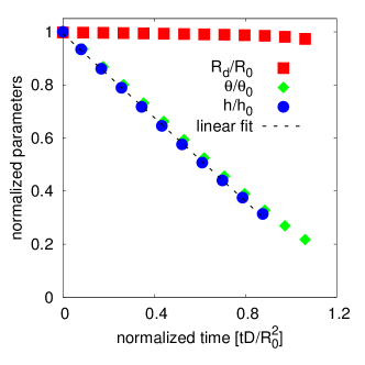
Fig. 2 shows the evolution of the normalized contact radius , the normalized droplet height , and the normalized contact angle versus time. The time is normalized with the diffusivity of the fluid, DennisXieJens2016 . During the evaporation, the contact angle of the droplet decreases while the contact radius keeps constant. This is the so-called CA mode Picknett1977 , resulting from the contact line pinning caused by contact angle heterogeneities of the substrate. The droplet height and contact angle decrease linearly.
The evaporation of a droplet with pinned contact line introduces an outward capillary flow inside the droplet Deegan1997 ; Popov2005 . Following the principle of mass conservation Marin2011 ; Deegan1997 ; Popov2005 and assuming an infinite size of the system, the evolution of the droplet height in the limit of small contact angles is obtained as
| (14) |
with denoting the total life time of the droplet. We note that Eq. (14) predicts that the droplet height decreases linearly with time, which is consistent with our simulation results shown in Fig. 2. Using the lubrication approximation Marin2011 , one can estimate the radial velocity near the substrate as
| (15) |
where is the average radial velocity and is given as
| (16) |
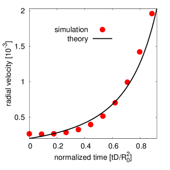
The term in Eq. (16) predicts that the radial velocity diverges near the end of the lifetime of the droplet, which is confirmed by experiments Marin2011 . For a detailed derivation, we refer the reader to the Appendix A.
In the simulations, we measure the radial velocity at position and compare the simulation data with the theoretical analysis Eq. (15) in Fig. 3. The total lifetime of the droplet is determined from a linear fit of the time evolution of the droplet height (dashed line shown in Fig. 2). The radial velocity increases with time and shows a rapid increase at later times, which agrees well with the theoretical prediction Eq. (15).
Next, we investigate the stick-slip mode of a drying droplet by creating a hydrophilic circular area with contact angle located at the center of the substrate and the remaining area is hydrophobic of contact angle . We place a droplet with an initial radius and an initial height , therefore, the initial contact angle is .
Fig. 4 shows the time evolution of the contact radius , the droplet height , and the contact angle of the evaporating droplet. In the beginning, the contact angle decreases while the contact radius keeps constant. This indicates that the contact line is pinned at the border between the hydrophilic and the hydrophobic area due to the wettability heterogeneities of the substrate. When the contact angles reaches , it stays constant, while the contact radius begins to decrease, indicating that a depinning of the contact line occurs. The droplet height decreases throughout the drying time of the droplet, but with a faster decreasing rate in the pinned phase than in the unpinned phase, which is consistent with experimental results Detlef2015 . Therefore, we demonstrate that our system is able to reproduce the stick-slip mode accurately by utilizing the patterned wettability of the substrate. We note that the stick-slip motion can also be triggered by the topological features on the substrate Pham2017 . For simplicity, we initialize the substrate with patterned wettability to introduce the stick-slip mode.
III.2 Colloidal suspension droplet
In the following we investigate the evaporation of a colloidal suspension droplet. We initialize the droplet with a particle volume concentration which corresponds to particles of radius . The particles are slightly hydrophilic with a contact angle and the substrate has a hydrophilic circular area with a contact angle located at the center surrounded by a hydrophobic area of contact angle . We note that the pure droplet shows a stick-slip drying mode on this specific substrate. We apply a constant friction force with magnitude following Eq. (13) between particles and substrate. Then, we let the system equilibrate and apply evaporation boundary conditions on the sides and the top of the system.
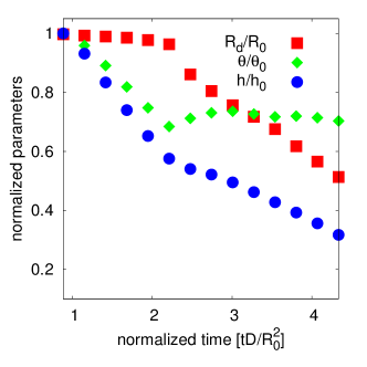
Firstly, we set the friction force to zero and investigate the contact line dynamics. Fig. 5 shows that the contact line of the colloidal suspension droplet initially follows the constant radius mode: the contact radius keeps constant and the contact angle decreases.


When the contact angle reaches , it slightly increases and then stays constant. Meanwhile, the contact radius begins to decrease, indicating that the contact line depins. The droplet height keeps decreasing in the whole process of drying, which is also observed in the stick-slip mode of a drying pure droplet. We note that the contact angle at the slip stage () is larger than the one observed for a pure droplet () (Fig. 4). The reason is that the particles accumulate at the contact line and serve as a new substrate. The contact line is pinned at the particle surface. Thus, the contact angle of the droplet is determined by the particle wettablity, i.e. .
We show the corresponding drying process of the colloidal suspension droplet without friction in Fig. 6. In the initial CR mode of evaporation, the particles are transported to the contact line and intend to pin the contact line (Fig. 6(a)). When the contact angle reaches a critical value, the contact line depins, recedes and pulls the particles inwards by the capillary force (Fig. 6(b)). Then, the contact line transits to the constant angle mode and the particles keep accumulating at the contact line (Fig. 6(c)). The capillary force keeps pulling particles inward, and finally they form a dot-like pattern (Fig. 6(d)).
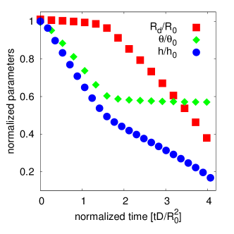
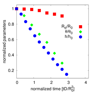
In order to investigate the influence of friction between particles and substrate, we set . Fig. 7 shows the time evolution of the contact radius , the droplet height and the contact angle of the evaporating colloidal suspension droplet. At first, the contact radius keeps constant and the contact angle decreases, which is similar to the behavior of a drying colloidal suspension droplet without friction, as shown in Fig. 5. Interestingly, when the contact angle decreases to , there is only a slight decrease of the contact radius, in contrast to the continuous decrease of the contact radius observed in the drying of a pure droplet and the drying of a colloidal suspension droplet without friction. Moreover, the contact angle keeps decreasing, which is similar to the constant radius mode observed for a drying pure droplet (Fig. 2).
To understand the behavior of the contact line, we show the drying process of the colloidal suspension droplet obtained in our simulations in Fig. 8. The particles are initially randomly distributed in the droplet and some are adsorbed at the droplet interface after equilibration. During evaporation in CR mode, the particles are transported to the contact line and accumulate there (Fig. 8(a)). At the end of the CR phase, the contact line intends to recede and tries to pull the particles to move inward through a capillary force. However, the particles are stuck at the substrate due to the large friction and introduce a pinning of the contact line (Fig. 8(b)). The droplet further dries and more particles are transported to the contact line forming a porous structure. The interface recedes through the porous structure, resulting in a slight decrease of the contact radius, as shown in Fig. 7. Near the end of the lifetime of the droplet, the contact angle decreases and the droplet flattens. This thin flat film breaks close to the ring (Fig. 8(c)), is dried rapidly, and finally a ring-like deposit is left (Fig. 8(d)).
We note that the magnitude of the friction force is chosen to be of the same order as the magnitude of the capillary force of the particles at the contact line, which has been calculated in the work of Sangani et al. Sangani2009 . In reality, the friction force arises from the normal load on the particles and the surface roughness of both, particles and substrate. For a possible experimental validation of our results, we refer to recent atomic force microscopy measurements of the friction force between particles and a substrate Guo2013 .


III.3 Theoretical model and discussion
We propose a simple theoretical model to consider the effect of the friction force on the effective radius of deposition. In the case of a dilute colloidal suspension droplet, we assume a uniform distribution of particles in the droplet during evaporation. Thus, the particle number density , where is the total number of particles, and is the initial droplet volumer, keeps constant inside the evaporating droplet and the remaining particles are transported to the contact line. For simplicity, we also assume that the particle deposition at the contact line is a monolayer and the particles are uniformly distributed along the contact line.
Fig. 9 depicts the aggregation of particles at the contact line. The outermost particle deforms the interface, thus a capillary force rises up and acts on the particle pointing inwards. Meanwhile, the outermost particle and its neighbouring particles along the radial direction experience a friction force , which resists the inward capillary force. We define the outermost particle and its neighbouring particles along the radial direction as a radial particle cluster. The contact line depins when the capillary force is larger than the total friction force , which is given by . Here, is the number of particles in the radial cluster.
During the constant radius phase of evaporation, the contact angle of the droplet decreases and the capillary force acting on the outermost particles increases. Meanwhile, more particles are transported to the contact line and accumulate there resulting in an increase of the total friction force. Therefore, the competition between capillary force and total friction force determines the moment of depinning of the contact line and the deposition pattern.
If the accumulated particles are not able to pin the contact line at the end of the constant radius phase (), the contact line depins and shrinks while the contact angle keeps constant. We assume the capillary force acting on the outermost particles to be constant. However, the total friction force increases due to the continuous accumulation of more particles at the contact line. When the total friction force becomes larger than the capillary force, the contact line is pinned at a position with a certain distance to the center of the hydrophilic area. The droplet continues to dry in constant radius mode and leaves a deposition pattern with an effective radius determined by
| (17) |
In order to derive an expression for , we assume that the droplet keeps a spherical cap with volume when the contact line is pinned at the position with distance to the center. The total number of particles that are transported to the contact line is given by . Based on a geometric analysis, we obtain
| (18) |
where is the maximal droplet height when the self-pinning happens. With the assumption that the particles form a circular ring (outer radius , inner radius ) at the contact line, we obtain its area as
| (19) |
The average number of particles in the radial particle cluster is then
| (20) |
Using Eq. (19) and Eq. (20), we can write Eq. (17) as
| (21) |
Based on Eq. (21), we note that the number of particles at the contact line directly affects the pinning of the contact line, which is consistent with the conclusion drawn in the work of Weon et al. Weon2013 that the particle packing fraction at the contact line plays an important role in self-pinning.
Here, we determine a critical value of the friction force below which the contact line depins at the end of the constant radius phase. At the end of the constant radius phase, the number of particles that are transported to the contact line is , where . We then obtain the critical value of the friction force as
| (22) |
If the friction force , the contact line depins and follows a constant angle mode. The contact angle of the droplet is and we can write . Inserting Eq. (18) into Eq. (21) and after some manipulations we obtain
| (23) |
We note that there should be a minimal radius of deposition where all particles are located around the center of the substrate. This minimal radius can be obtained as and allows to estimate the minimal friction force below which particles will always be located around the center as
| (24) |
To validate our theoretical analysis, we carry out simulations with different friction forces in the range . We define the effective radius of deposition in a way such that a circle of radius covers of all particles in the system.
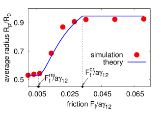
We solve Eq. (22), Eq. (23) and Eq. (24) with the simulation parameters , , , , . The capillary force is assumed to be constant and we estimate it as Sangani2009 . From Eq. (22) and Eq. (24) we obtain the critical friction force and the minimum firction force , respectively. In Fig. 10 we compare the simulation results (symbols) with our theoretical analysis (solid lines). The simulations show that the effective radius of deposition keeps constant until the friction force reaches the minimal friction force . Then, the effective radius increases for small friction forces, and finally reaches a plateau for large friction forces which is in a good agreement with our theoretical analysis. We note that the theoretical analysis predicts a lower value of the effective radius than simulation results at . A possible interpretation is that near the end of the lifetime of the droplet, while the particles are being pulled inwards, the droplet flattens, breaks up and dries quickly. Therefore, the capillary force vanishes and the particles stop moving, resulting a slightly higher effective radius than expected from the theoretical analysis.
We note that our theoretical analysis is only valid when the particles form a monolayer at the contact line, as observed in the experiments by Sangani at al. Sangani2009 . However, the multilayer structures are also observed in evaporation-driven deposition Abkarian2004 ; Marin2011 . Our theory can be extended to suit for multilayer cases with the structure of the multilayer being provided, such as the thickness of the multilayer along the radial direction.
IV Conclusion
We investigated the deposition of a drying droplet on a chemically patterned substrate and demonstrate that we are able to control the wettability of the substrate accurately to reproduce the constant radius mode and the stick-slip mode. When the droplet evaporates with a pinned contact angle, the radial velocity inside the droplet diverges near the end of the droplet lifetime, which is in a good agreement with theory and experiment.
We then studied the effect of friction between the particles and the substrate on the contact line dynamics and the final deposition pattern in drying colloidal suspension droplets. Without friction, the contact line shows a stick-slip drying mode similar to a drying pure droplet. Interestingly, due to the pinning of the contact line on the particles, the droplet in the slip stage has a larger contact angle than that of a pure droplet. Moreover, the particles follow the receding contact line and finally form a dot-like deposit.
With increasing the friction force, the drying suspension droplet shows a transition from stick-slip mode to constant radius mode. With a large friction force, the particles accumulate at the contact line, introducing self-pinning. Thus, more particles are transported to the contact line and form porous structures. Surprisingly, we find that the contact line recedes through the pores, resulting in a slight decrease of the contact radius.
Moreover, we propose a theoretical model for the effective radius of deposition as a function of the friction force. Our model predicts a critical friction force at which the self-pinning happens and a decreasing effective radius of the deposit with decreasing friction. Additionally, the effective radius of the particle deposit keeps constant for all friction forces smaller than a minimal friction. We carried out simulations and find good agreement between the simulation results and our theoretical predictions. Our results contribute to the fundamental understanding of self-pinning phenomena and can find implications for developing active control strategies for the deposition of drying droplets.
Finally, we note that after the pioneering work of Deegan et al. on the coffee-ring effect Deegan1997 , the understanding of the macroscopic mass and momentum transport phenomena in drying droplets is relatively well developed Deegan1997 ; Hu2005b ; Popov2005 ; Detlef2015 . However, the interfacial phenomena, contact-line and deposition processes in drying colloidal suspension droplets are not nearly as well understood Larson2014 . The available theoretical models usually apply a convection-diffusion equation governing the transport of colloidal particles Fleck2015 ; Pham2017 , which cannot account for phenomena at the scale of individual particles (e.g., contact-line pinning on particles, particle-particle interactions, particle-substrate interactions). We perform lattice Boltzmann simulations with fully resolved colloidal particles. Thus, we are able to fully resolve the information at the scale of individual particles and can gain more insight in the deposition process.
Acknowledgements.
Financial support is acknowledged from the Netherlands Organization for Scientific Research (NWO) through project 13291 and a NWO Industrial Partnership Programme (IPP). This research programme is co-financed by Océ-Technologies B.V., University of Twente and Eindhoven University of Technology. We thank the Jülich Supercomputing Centre and the High Performance Computing Center Stuttgart for the technical support and allocated CPU time.Appendix A Derivation of the radial fluid velocity in a drying droplet with pinned contact line
The average radial velocity can be derived assuming mass conservation Marin2011 . We consider a small volume . The mass conservation law of this controlled volume can be written as
| (25) |
where is the local height of the droplet surface, is the time, is the radial coordinate, is the volume flow, is the liquid density, and is the evaporative flux.
In the limit of small contact angles, the evaporative flux can be written as Deegan1997 ; Popov2005 ; Marin2011
| (26) |
with the diffusion constant for the droplet’s liquid in another fluid, and the difference between the liquid density just above the drop surface and the liquid density located far away from its surface. Here, we assume that the droplet has spherical cap shape and we obtain . We note that LBM can recovers Navier-stokes equation Succi2001 , thus we are able to simulate a droplet with larger contact angle and a spherical-cap shape, which goes beyond the limitation of lubrication theory based models of drying droplets DIDDENS2017 , where an assumption of a flat droplet is required.
Following global mass conservation, the change in droplet volume
| (27) |
should be equal to the total amount of evaporated liquid
| (28) |
Comparing Eq. (27), and Eq. (28), we obtain
| (29) |
The evolution of the droplet height is
| (30) |
with being the total life time of the droplet. We note that Eq. (30) predicts that the droplet height decreases linearly with time.
Inserting Eq. (30) and Eq. (26) into Eq. (25) and after some manipulations we obtain
| (31) |
The volume flow , where is the height averaged radial velocity. Using Eq. (31) and Eq. (30), it can be derived as
Following an approach proposed by Marin et al. Marin2011 based on the lubrication approximation, we can then estimate the radial velocity as
| (33) |
References
- [1] M. Singh, H. M. Haverinen, Pl. Dhagat, and G. E. Jabbour. Inkjet Printing—Process and Its Applications. Adv. Mater., 22:673–685, 2010.
- [2] S. Grainger and J. Blunt. Engineering Coatings. Woodhead Publishing, 1998.
- [3] R. D. Deegan, O. Bakajin, T. F. Dupont, G. Huber, S. R. Nagel, and T. A. Witten. Capillary Flow as the Cause of Ring Stains from Dried Liquid Drops. Nature, 389:827–829, 1997.
- [4] W. Han and Z. Lin. Learning from “Coffee Rings”: Ordered Structures Enabled by Controlled Evaporative Self-Assembly. Angew. Chem. Int. Ed., 51:1534–1546, 2012.
- [5] R. G. Larson. Transport and Deposition Patterns in Drying Sessile Droplets. AlChE J., 60:1538–1571, 2014.
- [6] M. Anyfantakis and D. Baigl. Manipulating the Coffee-Ring Effect: Interactions at Work. Chem. Phys. Chem., 16:2726–2734, 2015.
- [7] X. Zhong, A. Crivoi, and F. Duan. Sessile Nanofluid Droplet Drying. Adv. Colloid Interface Sci., 217:13–30, 2015.
- [8] J. Park and J. Moon. Control of Colloidal Particle Deposit Patterns within Picoliter Droplets Ejected by Ink-Jet Printing. Langmuir, 22:3506–3513, 2006.
- [9] C. Girotto, B. P. Rand, J. Genoe, and P. Heremans. Exploring Spray Coating as a Deposition Technique for the Fabrication of Solution-Processed Solar Cells. Sol. Energy Mater. Sol. Cells, 93:454–458, 2009.
- [10] R. G. Picknett and R. Bexon. The Evaporation of Sessile or Pendant Drops in Still Air. J. Colloid Interface Sci., 61:336–350, 1977.
- [11] A.-M. Cazabat and G. Guéna. Evaporation of Macroscopic Sessile Droplets. Soft Matter, 6:2591–2612, 2010.
- [12] D. Lohse and X. Zhang. Surface Nanobubbles and Nanodroplets. Rev. Mod. Phys., 87:981–1035, 2015.
- [13] M. E. R. Shanahan. Simple Theory of ”Stick-Slip” Wetting Hysteresis. Langmuir, 11:1041–1043, 1995.
- [14] J. M. Stauber, S. K. Wilson, B. R. Duffy, and K. Sefiane. On the Lifetimes of Evaporating Droplets. J. Fluid Mech., 744:1–12, 2014.
- [15] D. Orejon, K. Sefiane, and M. E. R. Shanahan. Stick–Slip of Evaporating Droplets: Substrate Hydrophobicity and Nanoparticle Concentration. Langmuir, 27:12834–12843, 2011.
- [16] T. Pham and S. Kumar. Drying of Droplets of Colloidal Suspensions on Rough Substrates. Langmuir, 33:10061–10076, 2017.
- [17] R. D. Deegan. Pattern Formation in Drying Drops. Phys. Rev. E., 61:475–485, 2000.
- [18] R. D. Deegan, O. Bakajin, T. F. Dupont, G. Huber, S. R. Nagel, and T. A. Witten. Contact Line Deposits in an Evaporating Drop. Phys. Rev. E., 62:756–765, 2000.
- [19] A. S. Sangani, C. Lu, K. Su, and J. A. Schwarz. Capillary Force on Particles near a Drop Edge Resting on a Substrate and a Criterion for Contact Line Pinning. Phys. Rev. E., 80:011603, 2009.
- [20] B. M. Weon and J. H. Je. Self-Pinning by Colloids Confined at a Contact Line. Phys. Rev. Lett., 110:028303, 2013.
- [21] Y. Li, H. Wu, and F. Wang. Effect of a Single Nanoparticle on the Contact Line Motion. Langmuir, 32:12676–12685, 2016.
- [22] X. Man and M. Doi. Ring to Mountain Transition in Deposition Pattern of Drying Droplets. Phys. Rev. Lett., 116:066101, 2016.
- [23] L. Espín and S. Kumar. Forced Spreading of Films and Droplets of Colloidal Suspensions. J. Fluid Mech., 742:495–519, 2014.
- [24] S. Succi. The Lattice Boltzmann Equation: For Fluid Dynamics and Beyond. Oxford University Press, 2001.
- [25] D. Raabe. Overview of the Lattice Boltzmann Method for Nano-and Microscale Fluid Dynamics in Materials Science and Engineering. Modell. Simul. Mater. Sci. Eng., 12:R13, 2004.
- [26] X. Shan and H. Chen. Lattice Boltzmann Model for Simulating Flows with Multiple Phases and Components. Phys. Rev. E, 47:1815, 1993.
- [27] H. Liu, Q. Kang, C. R. Leonardi, S. Schmieschek, A.l Narváez, B. D. Jones, J. R. Williams, A. J. Valocchi, and J. Harting. Multiphase Lattice Boltzmann Simulations for Porous Media Applications. Computat. Geosci., 20:777–805, 2016.
- [28] A. J. C. Ladd and R. Verberg. Lattice-Boltzmann Simulations of Particle-Fluid Suspensions. J. Stat. Phys., 104:1191–1251, 2001.
- [29] F. Jansen and J. Harting. From Bijels to Pickering Emulsions: a Lattice Boltzmann Study. Phys. Rev. E, 83:046707, 2011.
- [30] F. Günther, F. Janoschek, S. Frijters, and J. Harting. Lattice Boltzmann Simulations of Anisotropic Particles at Liquid Interfaces. Comput. Fluids, 80:184–189, 2013.
- [31] Q. Xie, Gary B. Davies, F. Günther, and J. Harting. Tunable Dipolar Capillary Deformations for Magnetic Janus Particles at Fluid-Fluid Interfaces. Soft Matter, 11:3581–3588, 2015.
- [32] S. Frijters, F. Günther, and J. Harting. Effects of Nanoparticles and Surfactant on Droplets in Shear Flow. Soft Matter, 8:6542–6556, 2012.
- [33] D. Hessling, Q. Xie, and J. Harting. Diffusion Dominated Evaporation in Multicomponent Lattice Boltzmann Simulations. J. Chem. Phys., 146:054111, 2017.
- [34] Y. H. Qian, D. D’Humières, and P. Lallemand. Lattice BGK models for Navier-Stokes equation. Europhys. Lett., 17:479–484, 1992.
- [35] H. Huang, D. T. Thorne, M. G. Schaap, and M. C. Sukop. Proposed Approximation for Contact Angles in Shan-and-Chen-Type Multicomponent Multiphase Lattice Boltzmann Models. Phys. Rev. E, 76:066701, 2007.
- [36] N. Martys and H. Chen. Simulation of Multicomponent Fluids in Complex Three-Dimensional Geometries by the Lattice Boltzmann Method. Phys. Rev. E, 53:743, 1996.
- [37] N. MURISIC and L. KONDIC. On Evaporation of Sessile Drops with Moving Contact Lines. J. Fluid Mech., 679:219–246, 2011.
- [38] C. K. Aidun, Y. Lu, and E.-J. Ding. Direct Analysis of Particulate Suspensions with Inertia Using the Discrete Boltzmann Equation. J. Fluid Mech., 373:287–311, 1998.
- [39] F. Janoschek, J. Harting, and F. Toschi. Accurate Lubrication Corrections for Spherical and Non-Spherical Particles in Discretized Fluid Simulations. arXiv:1308.6482, 2016.
- [40] C. Kunert, J. Harting, and O.I. Vinogradova. Random-Roughness Hydrodynamic Boundary Conditions. Phys. Rev. Lett., 105:016001, 2010.
- [41] H. Hertz. Über die Berührung fester elastischer Körper. Journal für die reine und angewandte Mathematik, 92:156, 1881.
- [42] M. Fujita, O. Koike, and Y. Yamaguchi. Direct Simulation of Drying Colloidal Suspension on Substrate using Immersed Free Surface Model. J. Comput. Phys., 281:421–448, 2015.
- [43] T. Pöschel and T. Schwager. Computational Granular Dynamics. Springer, 2005.
- [44] D. Guo, J. Li, L. Chang, and J. Luo. Measurement of the Friction between Single Polystyrene Nanospheres and Silicon Surface Using Atomic Force Microscopy. Langmuir, 29:6920–6925, 2013.
- [45] Y. O. Popov. Evaporative Deposition Patterns: Spatial Dimensions of the Deposit. Phys. Rev. E, 71:036313, 2005.
- [46] Á. G. Marín, H. Gelderblom, D. Lohse, and J. H. Snoeijer. Order-to-Disorder Transition in Ring-Shaped Colloidal Stains. Phys. Rev. Lett., 107:085502, 2011.
- [47] M. Abkarian, J. Nunes, and H. A. Stone. Colloidal Crystallization and Banding in a Cylindrical Geometry. J. Am. Chem. Soc., 126:5978–5979, 2004.
- [48] H. Hu and R. G. Larson. Analysis of the Effects of Marangoni Stresses on the Microflow in an Evaporating Sessile Droplet. Langmuir, 21:3972–3980, 2005.
- [49] N. A. Fleck, R. M. McMeeking, and T. Kraus. Convective Assembly of a Particle Monolayer. Langmuir, 31:13655–13663, 2015.
- [50] C Diddens, J. G. M. Kuerten, C. W. M. van der Geld, and H. M. A. Wijshoff. Modeling the Evaporation of Sessile Multi-Component Droplets. J. Colloid Interface Sci., 487:426–436, 2017.