Controlled doping of a bosonic quantum gas with single neutral atoms
Abstract
We report on the experimental doping of a 87Rubidium (Rb) Bose-Einstein condensate (BEC) with individual neutral 133Cesium (Cs) atoms. We discuss the experimental tools and procedures to facilitate Cs-Rb interaction. First, we use degenerate Raman side-band cooling of the impurities to enhance the immersion efficiency for the impurity in the quantum gas. We identify the immersed fraction of Cs impurities from the thermalization of Cs atoms upon impinging on a BEC, where elastic collisions lead to a localization of Cs atoms in the Rb cloud. Second, further enhancement of the immersion probability is obtained by localizing the Cs atoms in a species-selective optical lattice and subsequent transport into the Rb cloud. Here, impurity-BEC interaction is monitored by position and time resolved three-body loss of Cs impurities immersed into the BEC. This combination of experimental methods allows for the controlled doping of a BEC with neutral impurity atoms, paving the way to impurity aided probing and coherent impurity-quantum bath interaction.
I Introduction
Single impurities coupled to a Bose-Einstein condensate (BEC) form a model system underlying many theoretical proposals to exploit localization of impurities in a quantum gas. The applications of impurity-bath interaction include local probing of various quantum properties of many-body systems Bruderer and Jaksch (2006); Sabin et al. (2014); Correa et al. (2015); Elliott and Johnson (2016); Streif et al. (2016); Klein et al. (2007); Ng and Bose (2008), or cooling of impurities and quantum information carriers exploiting the properties of quantum fluids Daley et al. (2004); Griessner et al. (2006); Lausch et al. (2018).
An application which has attracted significant attention recently is the simulation of fascinating quantum impurity phenomena in solid state physics. For strong interactions, quasi-particles emerge which can have profoundly different properties compared to the uncoupled impurity. A prominent example is the recently observed formation of strong-coupling polarons in Bose-gases Hu et al. (2016); Jørgensen et al. (2016), where a detailed understanding of the ground state properties is currently emerging Bruderer et al. (2007); Blinova et al. (2013); Rath and Schmidt (2013); Li and Das Sarma (2014); Levinsen et al. (2015); Ardila and Giorgini (2015); Shchadilova et al. (2016). More generally, individual impurities with spin degree of freedom can realize an experimental model system for the spin-boson model Leggett et al. (1987) or the central spin model Prokof’ev and Stamp (2000), describing the properties of a spin in a bosonic or spin bath, respectively.
In order to realize a model system of individual neutral impurities in a quantum fluid, independent control of individual impurities within the BEC is necessary. This calls for experimental tools facilitating independent positioning of BEC atoms and impurities. So far, this has been achieved by either exploiting the spin degree of freedom, i.e. creating spin impurities Fukuhara et al. (2013), or by using electronically charged impurities such as ions or electrons Zipkes et al. (2010); Schmid et al. (2010); Balewski et al. (2013). However, these approaches imply either a fixed spin degree of freedom, or further experimental challenges due to the long-range atomic interaction potential for collisions in the quantum gas, which requires much smaller temperatures to enter the -wave interaction regime. An alternative route is to use neutral impurities, where technically the tools and methods of state preparation and independent position control have to rely on the multi-level structure of impurity and quantum gas.
This work outlines the experimental toolbox for controlled doping of a 87Rubidium (Rb) BEC with a small number of individual neutral 133Cesium (Cs) atoms. In section II we will introduce the methods to prepare a Rb BEC and individual laser cooled Cs atoms in close vicinity, and present two important methods facilitating doping of the BEC: Raman cooling and species selective transport of Cs atoms in an optical lattice. In section III we will first demonstrate how the effective Rb-Cs cross section can be enhanced by Cs cooling. We find that the efficiency to immerse a neutral Cs atom into a Rb gas crucially depends on the question if a single Rb-Cs collision occurs. Experimentally, we find that the scattered fraction of Cs atoms is increased when lowering the Cs temperature. Introducing a simple model, we reproduce the qualitative behavior of the Cs immersion probability. Second, we show how the species-selective optical lattice allows for deterministic immersion of impurities into the BEC by suppressing the axial Cs motion. Thereby, our work facilitates future studies of controllable impurity-bath interaction.
II Methods
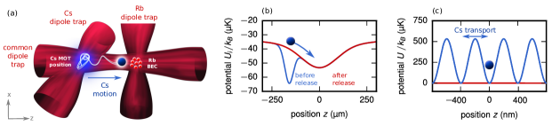
Our experiment produces Rb BECs in an all-optical configuration (Fig. 1) with typically atoms at temperatures around nK at a cycle time of approximately 7 s, for details see Hohmann et al. (2015). The Rb cloud is trapped in a crossed dipole trap comprising a horizontal beam with waist of and a vertical beam of waist . The final trapping frequencies in the combined, cigar-shaped trap are in the radial (axial) direction. The Rb cloud is probed by standard absorption imaging after time-of-flight.
Few Cs atoms are cooled and trapped in a high magnetic field gradient magneto-optical trap (MOT) and subsequently loaded into a crossed dipole trap. The dipole traps for Cs and Rb share the horizontal trapping beam while the crossing region for the Cs trap is located at a distance of approximately from the Rb BEC (see Fig. 1). Typically, the Cs atoms have temperatures in the order of after the transfer from the MOT to the dipole trap.
II.1 Raman cooling
While ultracold, the temperature of the laser-cooled Cs atoms still is more than one order of magnitude larger than the BEC temperature. The resulting small spatial overlap between the two species turns out to be a central obstacle for controlled impurity immersion. To further reduce the Cs temperature, we employ degenerate Raman-sideband cooling (DRSC), similar to ref. Kerman et al. (2000).
The optical setup combines a near-resonant optical lattice with an optical pumping beam in order to reduce the kinetic energy of the atoms. The optical lattice provides both an optical trapping potential as well as Raman coupling between adjacent states. The Raman lattice is created by three pairwise orthogonal beams with beam waists of approximately mm, referred to as A, B and Z+ (Fig. 2). The Z+ beam is propagating along the horizontal dipole axis with power of mW and is retro-reflected to create a fourth beam Z-. Beams A and B with a power of mW each propagate mutually orthogonal to each other, as well as with respect to the horizontal axis. They are polarized linearly in the plane defined by their propagation axes, while the beams Z+ and Z- are polarized vertically with a small polarization tilt of roughly between the two counter-propagating beams. The laser frequency of the Raman lattice beams is red detuned to the transition of the Cs -line by 6 MHz, where is the total atomic angular momentum.
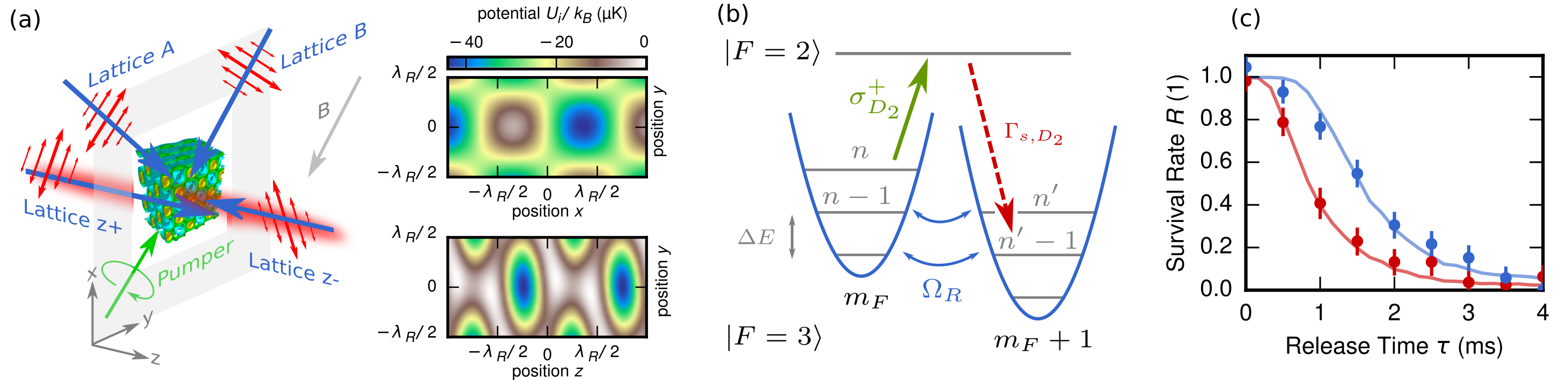
As the atoms are preferably in the state during the cooling cycle, this corresponds to a red shift of roughly 9 GHz. The interference between the four beams creates a 3D optical lattice pattern with a trap depth around and trapping frequencies of kHz (with the Boltzmann constant ). The lattice beams also drive the Raman transitions in the manifold with coupling strength and repump Cs atoms from into the cooling cycle in the case of off-resonant excitation. In order to reach degeneracy of vibrational energy levels with quantum number in adjacent states and in the Raman lattice potential, the magnetic background field is tuned to an experimentally optimized value of 100 mG. The optical pumping beam is resonant on the line and pumps atoms in a -transition from the manifold to the manifold where they spontaneously emit a photon () and decay back to . The pump beam is right-hand circularly polarized with a small amount of linear polarization and blue detuned by MHz to the transition. The Lamb-Dicke parameter for spontaneous decay is for the smallest (largest) trap frequency in the Raman lattice, with the single-photon recoil energy . This indicates that the vibrational quantum number is conserved for most of these photon scattering processes, hence the Cs energy is reduced by in each Raman cycle and therefore the atoms are cooled. During the Raman cooling, the position of a Cs atom remains confined in the optical lattice, while the kinetic energy is reduced and the Cs population is pumped to with about fidelity.
We determine the temperature directly after Raman cooling with a release-recapture technique, where the dipole trapping potential is switched off for a short duration and the remaining fraction of atoms is measured as a function of switch-off durations Mudrich et al. (2002); Reymond et al. (2003); Hohmann et al. (2016). Colder atoms have smaller velocities, therefore leaving the trapping volume more slowly and thus have a higher recapture probability. We extract the Cs temperature by comparing the experimental data to simulated curves which are generated in a Monte-Carlo simulation for Cs samples at different temperatures. After a single Raman cooling pulse, we measure a Cs temperature of (Fig. 2).
II.2 Independent position control
While the loading of the two species takes place at distant positions along the shared trapping beam, the atomic density distributions need to be overlapped to facilitate interaction. A key tool for independent position control of neutral Cs atoms with respect to the Rb cloud is a species-selective lattice (Fig. 1). Its operation relies on the multi-level structure of atoms. Adding all light-shift contributions, for alkali atoms usually the two fine-structure lines are considered, one finds that between the Rb D-lines the resulting dipole potential has a zero crossing at the so-called tune-out wavelength LeBlanc and Thywissen (2007). Consequently, at a wavelength around nm, Rb atoms do not experience a dipole potential for a specific choice of light polarization and atomic hyperfine state Leonard et al. (2015); Schmidt et al. (2016). For Cs atoms, however, the light field exerts a repulsive potential (Fig. 1).
Using two counter-propagating laser beams at the tune-out wavelength, we realize a species-selective 1D optical lattice which confines the Cs atoms axially, while the radial confinement originates from the horizontal dipole trap. A small detuning between the frequencies of the two beams forming the lattice, sets the standing wave into motion and enables controlled transport of Cs atoms from the loading region along the horizontal trapping axis, while Rb remains static at its trap position Schrader et al. (2001).
III Results
We characterize the immersion of individual Cs atoms into the BEC by two complementary approaches. In a first step, we employ Raman cooling to effectively compress the spatial distribution of Cs atoms in the trap due to the reduced temperature. Thus, the density-density overlap is sufficiently large to study Rb-Cs interaction with individual Cs atoms. In a scattering experiment of few Cs atoms impinging on a Rb cloud we show that the effective Rb-Cs immersion probability is large enough to thermalize Cs atoms in the Rb BEC via elastic collisions. This is indicated by a localization of Cs atoms in the Rb crossed dipole trap. Second, we further enhance the immersion efficiency by localizing Cs atoms in the species-selective lattice and transport them to the position of the BEC. We study the position resolved loss of Cs after being transported to the trap center, which reveals enhanced loss in the vicinity of the Rb BEC.
III.1 Effective immersion probability between impurity and cloud
In order to probe the effective Rb-Cs immersion probability, we first prepare a Rb cloud in the Rb crossed trap at various conditions, either in a thermal state with peak densities of and typical width of () radially (axially), or as a BEC with peak densities of and Thomas-Fermi radii of () radially (axially). Cs atoms are trapped in the MOT and subsequently transferred into the Cs crossed trap.
The choice of dipole trap potential depth () for Rb (Cs) during the Rb-Cs interaction is a compromise between providing sufficient confinement for reliable Cs atom trapping and avoiding a heating of the BEC at high densities induced by three-body loss. Due to the strong radial confinement and the similarity of trap frequencies of Cs and Rb, the difference of the gravitational sag is in the order of and is negligible compared to typical radial extensions of the atomic clouds ().
For the measurement, Cs atoms are prepared first directly from the MOT with uncontrolled hyperfine state and temperatures in the order of ; or second with an additional Raman cooling step yielding temperatures of in . Subsequently, the Cs atoms are released from the Cs crossed dipole trap and move in the horizontal trapping beam toward the center, where the Rb cloud is prepared (Fig. 1). After half an oscillation period, the Cs distribution is frozen by quickly applying a strong optical lattice potential, suppressing tunneling as well as thermal diffusion. After the Rb cloud has been removed from the trap by a resonant laser pulse, the Cs atoms in the 1D optical lattice are detected by in-situ fluorescence imaging. The axial Cs density distribution is obtained from hundreds of fluorescence images for each experimental setting.
It has been shown that essentially a single collision of Cs with a Rb bath atom dissipates sufficient energy so that the Cs atom remains trapped in the crossed Rb trapping region Hohmann et al. (2017). By contrast, the fraction of atoms which have not experienced a collision will freely oscillate to the turning point of the potential.
Experimentally, half an oscillation period after the release from the MOT, here ms, the interacting () and non-interacting () Cs fractions are maximally separated and can be well distinguished in our position-resolved fluorescence images (Fig. 3(b)). The relative number of Cs atoms in the Rb trapping region is thus a measure of the effective immersion probability. The results of such scattering measurements are shown in fig. 3 for different situations. First, Cs atoms with MOT temperature of impact a thermal Rb gas with and atoms. From the data in Fig. 3(b) we conclude that a large fraction of of Cs atoms collides with Rb atoms in the cloud and thermalizes with it. By contrast, if the Rb cloud is condensed (nK), the thermalized fraction is drastically reduced to as shown in Fig. 3(c). This is due to the reduced size of the Rb BEC () compared to the thermal cloud (), and many Cs atoms are radially too far away from the Rb BEC to undergo a first collision. Thus, the effective immersion probability is reduced.
In order to model the scattered fraction of Cs atoms, we introduce the position dependent Rb-Cs scattering rate for a Cs atom at position . Here, is the Rb density distribution in the trap including BEC and thermal fraction. Assuming a Maxwell-Boltzmann distributed kinetic energy distribution, the mean relative velocity between Cs and Rb atoms Mosk et al. (2001) is approximated by
| (1) |
is the scattering cross section with the Rb-Cs s-wave scattering length Takekoshi et al. (2012) and the Bohr radius . Neglecting the radial motion of the Cs atoms in the trap, we assume that they impinge on the Rb cloud in axial direction at velocity given by their initial potential energy in the dipole trap . We calculate the scattering probabilities for these straight trajectories at different radii from the trap center by evaluating the survival probabilities in regions of length along the trajectory in direction
| (2) |
Comparing this radial scattering probability to the Cs radial distribution (Fig. 3 (e-g)), we find that the immersed Cs fraction is reduced for lower Rb cloud temperatures due to the smaller Rb cloud size. The model also illustrates that the effective immersion probability can be increased again by lowering the temperature of the Cs impurities (Fig. 3 (h)).
Experimentally, a series of Raman cooling pulses is employed to further cool the Cs atoms. We use three Raman cooling pulses of 2 ms duration each, separated by a waiting time of between two pulses. The waiting time is adjusted to the radial trapping frequency and matches a quarter oscillation period. The first Raman pulse will hence reduce the Cs atoms’ kinetic energy. After a quarter oscillation period the remaining potential energy is converted to kinetic energy, which is dissipated by the second Raman pulse. More than two pulses are necessary because the trap is not perfectly harmonic; the number of three is chosen as a compromise, as every Raman pulse leads to a loss of a small fraction of Cs atoms (). Fig. 3(d) shows the Cs distribution when the Cs atoms have been Raman cooled. In this configuration, a fraction of of impurities is immersed into the Rb BEC through collisions with the Rb cloud.
This measurements illustrate how the effective immersion probability can been significantly increased, which enables controlled production of individual Cs impurities in a Rb BEC for future investigations.
III.2 Controlled doping and impurity lifetime
In a complementary approach to implant Cs impurities in the BEC, we exploit the species-selectivity of our optical lattice to transport Cs impurities into the BEC. In addition, after establishing interaction, the lattice is used to pin the Cs position within the Rb cloud. This allows to resolve the interaction dynamics without motion of the Cs impurities along the horizontal trapping beam. We monitor the position resolved loss of Cs atoms for increasing interaction time, which is strongly enhanced in a BEC due to frequent Rb-Rb-Cs three-body recombination events.
To this end, we prepare a Rb BEC of approximately atoms with a Thomas-Fermi radius of in axial direction. Raman-cooled Cs atoms are loaded into the species-selective lattice and transported into the BEC. Then, the lattice is used to transport the Cs atoms to various positions around the expected positions of the Rb cloud, intentionally broadening the Cs distribution axially.
Specifically, Cs atoms are distributed by choosing axial transport distances in the range of about . The transport lattice depth of () is chosen to yield sufficient confinement for Cs during the transport with an axial trapping frequency of . At the same time this choice avoids an excessive heating of the Rb cloud due to off-resonant photon scattering: For the lattice power used here, the remaining scattering rate on both lines is . After the transport, the lattice depth is further reduced (factor of ), when fixing the axial Cs position during the Rb-Cs interaction.
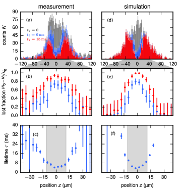
Cs atoms experience frequent collisions within the dense Rb cloud. In addition to elastic collisions, leading to fast thermalization of the Cs atoms, inelastic Rb-Rb-Cs collisions occur, which result in a loss of Cs atoms through molecule formation. The Cs distribution is measured after different interaction times , revealing the emergence of a hole at the position of the Rb BEC (Fig. 4 (a)). Thus, the losses demonstrate the successful immersion of individual Cs atoms into the Rb BEC.
We extract the position-resolved lifetime of Cs atoms in the BEC by first sorting the Cs positions extracted from the fluorescence images into a histogram with bins of about width. For each bin and interaction duration , the fraction of atoms lost is calculated as , where denotes the initial Cs atom number of bin . This normalization allows calculating the position dependent lifetime independently from the shape of the initial Cs distribution (Fig. 4(b)). For each position bin the lifetime is extracted by fitting an exponential decay to the remaining fraction (Fig. 4(c)). We find the shortest Cs lifetimes of only few ms at the expected center position of the BEC.
We compare the measurement to a Monte-Carlo model, where thermalization and loss dynamics for independent atomic Cs trajectories are simulated, assuming thermalized Cs atoms in the Rb BEC. For each atom in the Monte-Carlo sample which is as large as the experimental atom number, the equation of motion in the trapping potential (dipole trap and gravity) is integrated, as discussed in Hohmann et al. (2017). Elastic collisions with the Rb bath, as well as three-body loss are incorporated by evaluating the probabilities of an elastic collision and atom loss in each integration step of length .
For the calculation of elastic rate and loss rate , a continuous Rb distribution with the expected in-trap density of the BEC consisting of thermal background and BEC Thomas-Fermi distribution is assumed.
The elastic collisions rate writes with the low-momentum -wave scattering cross section introduced in section III.1.
In contrast to section III.1, here the relative velocity in the collision is evaluated, taking the current velocity and the bath temperature into account Hohmann et al. (2017).
The three-body loss rate writes with an independently obtained loss coefficient .
Properties of the BEC were determined independently, so the Monte-Carlo simulation is conducted without free parameters.
For the Monte-Carlo simulation, the position resolved lifetime is extracted analogously to the measurement (compare fig. 4(c), (f)) and is in agreement with the measured data.
The simulation reveals that about of Cs atoms are lost within the Thomas-Fermi radius of the BEC, although only of Rb atoms are condensed, demonstrating the enhanced density overlap of the condensate fraction at the trap center.
While in the previous section it has been shown that interaction of impurities with the BEC through elastic collisions leads to thermalization and a localization of Cs atoms at the trap center, here we show that inelastic collision events can serve as indicator of successful impurity immersion into the BEC.
IV Conclusion
We have experimentally studied the interaction of individual Cs impurities with a Rb BEC. For laser-cooled impurities from a MOT, we find that the effective Rb-Cs scattering probability is too small to ensure efficient immersion of Cs in the Rb BEC. We demonstrate how the scattering probability can then be enhanced by further cooling of the impurity, which we have implemented by a series of Raman cooling pulses. This effectively compresses the impurity density distribution in the trap. We have measured this increased immersion probability by observing thermalization and localization in the Rb cloud. Further enhancement of the immersion efficiency is obtained by axially localizing the Cs atoms in a species-selective optical lattice and transporting them into the Rb cloud. A position resolved measurement of the Cs atom loss rate reveals a strong signature of the interaction between Cs impurity and Rb BEC. Thereby, our results pave the way for future investigations of coherent interactions between impurities and a quantum gas.
Acknowledgements
We thank Michael Hohmann and Farina Kindermann for their help in initially constructing the experiment and for initial discussions, and Valeryia Mikhaylova for preparing illustrations of the experimental details. This work was funded in the early stage by the European Union via ERC Starting grant ”QuantumProbe”; equipment was partially contributed by Deutsche Forschungsgemeinschaft via Sonderforschungsbereich (SFB) SFB/TRR185. D.M. acknowledges funding via SFB/TRR49, T.L. acknowledges funding by Carl Zeiss Stiftung, and F.S. acknowledges funding by the Studienstiftung des deutschen Volkes.
References
- Bruderer and Jaksch (2006) M. Bruderer and D. Jaksch, New Journal of Physics 8, 87 (2006).
- Sabin et al. (2014) C. Sabin, A. White, L. Hackermüller, and I. Fuentes, Sci. Rep. 4, 6436 (2014).
- Correa et al. (2015) L. A. Correa, M. Mehboudi, G. Adesso, and A. Sanpera, Phys. Rev. Lett. 114, 220405 (2015).
- Elliott and Johnson (2016) T. J. Elliott and T. H. Johnson, Phys. Rev. A 93, 043612 (2016).
- Streif et al. (2016) M. Streif, A. Buchleitner, D. Jaksch, and J. Mur-Petit, Phys. Rev. A 94, 053634 (2016).
- Klein et al. (2007) A. Klein, M. Bruderer, C. S. R., and D. Jaksch, New J. Phys. 9, 411 (2007).
- Ng and Bose (2008) H. T. Ng and S. Bose, Phys. Rev. A 78, 023610 (2008).
- Daley et al. (2004) A. J. Daley, P. O. Fedichev, and P. Zoller, Phys. Rev. A 69, 022306 (2004).
- Griessner et al. (2006) A. Griessner, A. J. Daley, S. R. Clark, D. Jaksch, and P. Zoller, Phys. Rev. Lett. 97, 220403 (2006).
- Lausch et al. (2018) T. Lausch, A. Widera, and M. Fleischhauer, Phys. Rev. A 97, 023621 (2018).
- Hu et al. (2016) M.-G. Hu, M. J. Van de Graaff, D. Kedar, J. P. Corson, E. A. Cornell, and D. S. Jin, Phys. Rev. Lett. 117, 055301 (2016).
- Jørgensen et al. (2016) N. B. Jørgensen, L. Wacker, K. T. Skalmstang, M. M. Parish, J. Levinsen, R. S. Christensen, G. M. Bruun, and J. J. Arlt, Phys. Rev. Lett. 117, 055302 (2016).
- Bruderer et al. (2007) M. Bruderer, A. Klein, S. R. Clark, and D. Jaksch, Phys. Rev. A 76, 011605 (2007).
- Blinova et al. (2013) A. A. Blinova, M. G. Boshier, and E. Timmermans, Phys. Rev. A 88, 053610 (2013).
- Rath and Schmidt (2013) S. P. Rath and R. Schmidt, Phys. Rev. A 88, 053632 (2013).
- Li and Das Sarma (2014) W. Li and S. Das Sarma, Phys. Rev. A 90, 013618 (2014).
- Levinsen et al. (2015) J. Levinsen, M. M. Parish, and G. M. Bruun, Phys. Rev. Lett. 115, 125302 (2015).
- Ardila and Giorgini (2015) L. A. P. n. Ardila and S. Giorgini, Phys. Rev. A 92, 033612 (2015).
- Shchadilova et al. (2016) Y. E. Shchadilova, F. Grusdt, A. N. Rubtsov, and E. Demler, Phys. Rev. A 93, 043606 (2016).
- Leggett et al. (1987) A. J. Leggett, S. Chakravarty, A. T. Dorsey, M. P. A. Fisher, A. Garg, and W. Zwerger, Rev. Mod. Phys. 59, 1 (1987).
- Prokof’ev and Stamp (2000) N. V. Prokof’ev and P. C. E. Stamp, Reports on Progress in Physics 63, 669 (2000).
- Fukuhara et al. (2013) T. Fukuhara, A. Kantian, M. Endres, M. Cheneau, P. Schauß, S. Hild, D. Bellem, U. Schollwöck, T. Giamarchi, C. Gross, I. Bloch, and S. Kuhr, Nature Physics 9, 235 (2013).
- Zipkes et al. (2010) C. Zipkes, S. Palzer, C. Sias, and M. Köhl, Nature 464, 388 (2010).
- Schmid et al. (2010) S. Schmid, A. Härter, and J. H. Denschlag, Phys. Rev. Lett. 105, 133202 (2010).
- Balewski et al. (2013) J. B. Balewski, A. T. Krupp, A. Gaj, D. Peter, H. P. Büchler, R. Löw, S. Hofferberth, and T. Pfau, Nature 502, 664 (2013).
- Hohmann et al. (2015) M. Hohmann, F. Kindermann, B. Gänger, T. Lausch, D. Mayer, F. Schmidt, and A. Widera, EPJ Quantum Technology 2, 1 (2015).
- Kerman et al. (2000) A. J. Kerman, V. Vuletić, C. Chin, and S. Chu, Phys. Rev. Lett. 84, 439 (2000).
- Mudrich et al. (2002) M. Mudrich, S. Kraft, K. Singer, R. Grimm, A. Mosk, and M. Weidemüller, Phys. Rev. Lett. 88, 253001 (2002).
- Reymond et al. (2003) G. Reymond, N. Schlosser, I. Protsenko, and P. Grangier, Philosophical Transactions of the Royal Society of London A: Mathematical, Physical and Engineering Sciences 361, 1527 (2003).
- Hohmann et al. (2016) M. Hohmann, F. Kindermann, T. Lausch, D. Mayer, F. Schmidt, and A. Widera, Phys. Rev. A 93, 043607 (2016).
- LeBlanc and Thywissen (2007) L. J. LeBlanc and J. H. Thywissen, Phys. Rev. A 75, 053612 (2007).
- Leonard et al. (2015) R. H. Leonard, A. J. Fallon, C. A. Sackett, and M. S. Safronova, Phys. Rev. A 92, 052501 (2015).
- Schmidt et al. (2016) F. Schmidt, D. Mayer, M. Hohmann, T. Lausch, F. Kindermann, and A. Widera, Phys. Rev. A 93, 022507 (2016).
- Schrader et al. (2001) D. Schrader, S. Kuhr, W. Alt, M. Müller, V. Gomer, and D. Meschede, Applied Physics B 73, 819 (2001).
- Hohmann et al. (2017) M. Hohmann, F. Kindermann, T. Lausch, D. Mayer, F. Schmidt, E. Lutz, and A. Widera, Phys. Rev. Lett. 118, 263401 (2017).
- Mosk et al. (2001) A. Mosk, S. Kraft, M. Mudrich, K. Singer, W. Wohlleben, R. Grimm, and M. Weidemüller, Applied Physics B 73, 791 (2001).
- Takekoshi et al. (2012) T. Takekoshi, M. Debatin, R. Rameshan, F. Ferlaino, R. Grimm, H.-C. Nägerl, C. R. Le Sueur, J. M. Hutson, P. S. Julienne, S. Kotochigova, and E. Tiemann, Phys. Rev. A 85, 032506 (2012).