Skyrmion Topological Hall Effect near Room Temperature
Abstract
Magnetic skyrmions are stable nanosized spin structures that can be displaced at low electrical current densities. Because of these properties, they have been proposed as building blocks of future electronic devices with unprecedentedly high information density and low energy consumption. The electrical detection of skyrmions via the Topological Hall Effect (THE), has so far been demonstrated only at cryogenic temperatures. Here, we report the observation of a skyrmion Topological Hall Effect near room temperature (276 K) in a mesoscopic lamella of FeGe. This region unambiguously coincides with the skyrmion lattice location revealed by neutron scattering. We provide clear evidence of a reentrant helicoid magnetic phase adjacent to the skyrmion phase, and discuss the large THE amplitude (5 n.cm) in view of the ordinary Hall Effect.
Magnetic skyrmions are nanometre size quasiparticles with a whirling spin configuration, which hold great potential as information carriers for electronic devicesNagaosa and Tokura (2013); Fert et al. (2017, 2013); Finocchio et al. (2016); Liu and Li (2015). Magnetic skyrmions were first studied theoreticallyBelavin and Polyakov (1975); Bogdanov and Yablonskii (1989); Rößler et al. (2006), and have recently been evidenced experimentally in B20 chiral materialsMuhlbauer et al. (2009); Yu et al. (2011) and in multilayer ferromagnetic thin filmsBoulle et al. (2016). Most skyrmionic materials have in commonNagaosa and Tokura (2013); Fert et al. (2017) the presence of an antisymmetric exchange interaction, known as Dzyaloshinskii–Moriya (DM) interactionDzialoshinskii (1957); Moriya (1960), favoring spin canting in materials that would otherwise be ferromagnetic with parallel aligned spins. The DM interaction occurs in materials with spin–orbit coupling and a structure lacking inversion symmetry. In B20 magnets such as MnSiMuhlbauer et al. (2009) and FeGeYu et al. (2011), this emerges from a heavy magnetic element in a non-centrosymmetric crystalline structure. In multilayer ferromagnetic thin films, the DM interaction is engineered by combining ultrathin layers of heavy metal and ferromagnetic materials, in which the heavy metal provides the large spin-orbit coupling while the interface between layers breaks the inversion symmetryFert et al. (2013). For a large enough DM interaction, such as that found in B20 magnets, the ground state of the material is helical. In this state, the spins form helices with a pitch of a few tens of nanometers typically. This pitch scales as J/D, where D is the DM interaction constant and J is the exchange energyNagaosa and Tokura (2013). This pitch is referred to as the helical wavelength and it sets the skyrmion size in bulk materials.
The topologically non-trivial whirling configuration of skyrmions spin texture can be characterized by the topological charge that is for an individual skyrmion, and null for topologically trivial structures such as magnetic bubbles. The topologically non-trivial structure of magnetic skyrmions makes them relatively stable because they cannot be continuously deformed to another magnetic stateNagaosa and Tokura (2013); Braun (2012).
A key advantage of magnetic skyrmions as stable nano-objects is that they can be displaced using relatively low electrical currentsJonietz et al. (2011); Schulz et al. (2012); Fert et al. (2013). This low critical current stems from the relative insensitivity of skyrmions to disorder due to the strong Magnus force contribution to the skyrmion dynamics that allows skyrmions to bypass defectsFinocchio et al. (2016); Liu and Li (2015); Nagaosa and Tokura (2013); Reichhardt et al. (2015). Such current manipulation enables not only data storage but also logic devices using magnetic “racetrack” type circuitsFert et al. (2017, 2013). Skyrmions nanometer size (10 nm = 6 Tbit/in2), stability and low critical current (106 A/m2) could thus yield non-volatile electronic devices with unprecedentedly high information density and low energy consumption.
One of the key issues for future “skyrmionic” devices is to develop a method for detecting skyrmions through electrical means. Electrical manipulation of skyrmions was demonstrated by visualization techniques at room temperature a few years agoIwasaki et al. (2013); Zhang et al. (2015); Jiang et al. (2015); Büttner et al. (2015); Woo et al. (2016); Juge et al. (2017). Yet it is only very recently, probably because of the sensitive measurements required, that electrical detection of skyrmions was demonstrated for isolated metastable skyrmions generated by interfacial DM interaction in multilayer thin filmsMaccariello et al. (2018) using the Anomalous Hall Effect (AHE). This detection relied on the large change of magnetization, and the concomitant large change in anomalous Hall Effect, introduced by a skyrmion in a ferromagnetic background. This effect is however not readily applicable to bulk skyrmion compounds, so-called B20 chiral magnets, because the skyrmion lattice does not introduce a significant step-change in magnetization over the background. Indeed, because of the larger DM interaction in B20 compounds, the background that surrounds the thermodynamically stable skyrmion lattice phase is a conical phase with a winding spins configuration, rather than a ferromagnetic phase.
Thus, a more practical way of detecting skyrmions in bulk compounds is to use skyrmions Topological Hall Effect (THE). This effect originates from electrons accumulating a Berry phase as they travel through skyrmions spin configuration, which acts as an effective magnetic field (). To first order, the skyrmion THE amplitude is proportional to , which itself is inversely proportional to a skyrmion cross-section area. The skyrmion THE is usually a few n.cm, and it arises in addition to the ordinary (OHE) and anomalous Hall Effect (AHE) in the transverse resistivity of skyrmionic compounds. The skyrmion THE has so far only been detected and unambiguously correlated with skyrmions imaging in the MnSi family of compounds at cryogenic temperaturesNeubauer et al. (2009a); Schulz et al. (2012); Franz et al. (2014); Liang et al. (2015).
Recently, two bulk materials have been unambiguously shown by Lorentz Transmission Electron Microscopy (LTEM) and Small Angle Neutron Scattering (SANS) to have a skyrmions lattice near or at room temperature: Co-Zn-Mn alloysTokunaga et al. (2015); Yu et al. (2017), and cubic FeGeYu et al. (2011, 2012); McGrouther et al. (2016); Stolt et al. (2016); Moskvin et al. (2013). In FeGe, magnetizationWilhelm et al. (2011), specific heat measurementsCevey et al. (2013), and microwave absorption spectroscopyTurgut et al. (2017) also identified several magnetic phases compatible with skyrmions. But bulk skyrmions THE near room temperature had so far not been observed. A few transport studies in FeGe thin filmsHuang and Chien (2012); Porter et al. (2014); Kanazawa et al. (2015) did report very large Hall signature at cryogenic temperatures. However, skyrmions have not been confirmed by imaging techniques in thin films of FeGeZhang et al. (2017). All LTEM measurements were performed on lamellae extracted from bulk FeGe single crystals Yu et al. (2011, 2012); McGrouther et al. (2016). Thus, it is therefore still debated whether the unusually large Hall signal, orders of magnitude larger than in bulk MnSi, observed in thin films at cryogenic temperature comes from a skyrmionic THE or has another originMeynell et al. (2014); Monchesky et al. (2014).
Here, we demonstrate the first electrical detection of skyrmions near room temperature in a bulk crystal: using high sensitivity Hall Effect measurements in FeGe, we observe a skyrmion THE of amplitude +5 n.cm at 276 K (3°C). This THE unambiguously coincides with the skyrmion lattice phase identified by small angle neutron scatteringMoskvin et al. (2013), and its amplitude is as large as the THE observed in MnSi at 29 K. Adjacent to the skyrmion phase, we also observe the signature of a magnetic phase that is not present in the prototypical skyrmion compound MnSi, and merges into the inhomogeneous chiral spin stateWilhelm et al. (2016). Finally, comparing THE in MnSi and FeGe we emphasize the failings of the formula that is generally used to estimate the skyrmion THE.
Results and Discussion
Electrical Transport Measurements
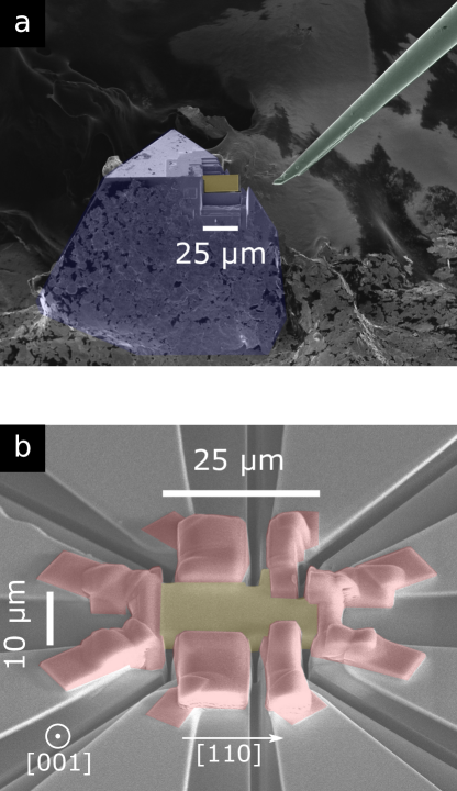
We prepared a 0.75 µm thick lamella of FeGe from a single crystal using a Focused Ion Beam microscope (FIB). Fig. 1.a shows the lamella before lift-out from the single crystal, and Fig. 1.b shows the lamella with Pt electrodes deposited by FIB. We then measured the electrical transport properties of this lamella which shows transport properties consistent with bulk crystals (see SI). Fig. 2.a. shows the temperature dependence of the longitudinal resistivity in zero magnetic field. The overall dependence and absolute value of is in agreement with the literaturePorter et al. (2014). The residual resistivity ratio is 8.5, higher than the value of 4 – 5 typically found in thin filmsPorter et al. (2014); Huang and Chien (2012) but below the values of 13 to 25 found in large single crystalsYeo et al. (2003); Pedrazzini et al. (2007). The magnetic transition from the paramagnetic phase to the helical phase appears as a subtle but clear kink around 279 K in the zero-field data (inset of Fig. 2.a).
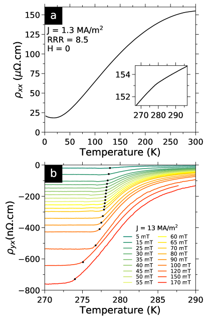
In Fig. 2.b., we show the temperature dependence of the Hall Effect of the lamella (using the same sign convention as in Ref. Neubauer et al. (2009b); Huang and Chien (2012); Porter et al. (2014), that is positive for electrons dominated transport). Electrical conduction appears to be predominantly hole type as is negative around (270-290 K). The onset of the increase in with increasing temperature, marks the transition from the conical to the paramagnetic phase indicated by black circles in Fig.2. All curves are constant in the conical phase in the temperature range we measured. For each magnetic field value, we define a transition temperature as 5% of the increase in between the flat baseline at 270 K and the value at 290 K. The magnetic field dependence of this transition temperature is in good agreement with previous magnetization studies in a bulk sampleWilhelm et al. (2011, 2016).
The Hall Effect in skyrmionic compounds typically consists of three terms
| (1) |
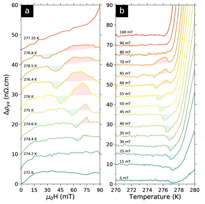
The first term is the Ordinary Hall Effect proportional to the applied magnetic field, the second term is the Anomalous Hall Effect proportional to the magnetization of the sample and the third term is the THE induced by the spin texture of skyrmions. Here, we find that curves are linear in the conical phase, as expected. Indeed the Ordinary Hall Effect and the Anomalous Hall Effect are both linear in H, as the magnetization is proportional to H in this phaseWilhelm et al. (2011). So, to better see variations from the conical state, we subtracted the total linear contribution from curves in the same manner as Ref. Neubauer et al. (2009b). The slope of the linear fit of in the conical phase (between 270 and 271K), is n.cm/mT with . We subtracted this slope from all curves and defined the resulting deviation of to the conical phase as . curves are shown in Fig. 3.a (shifted for clarity). As the conical contribution is constant in temperature, converting curves to corresponds to adding an offset to each curve shown in Fig. 2.b.
Signatures in the Hall Effect
In Fig. 3.a, the curves below 274.4 K show several features. A change in slope at mT separates the helical and conical phases, at low and high field respectively. curves are flat in the conical phase, consistent with the definition of . The upturn at higher fields (shown at 277.25 K) corresponds to the field polarized state. The helical-to-conical signature disappears above K, in agreement with magnetization studiesWilhelm et al. (2011, 2016). In addition to the helical, conical and field polarized states, we observe a local maximum and minimum that appear simultaneously inside the conical phase. The maximum and minimum have maximum amplitude at 276 K of n.cm and n.cm, respectively.
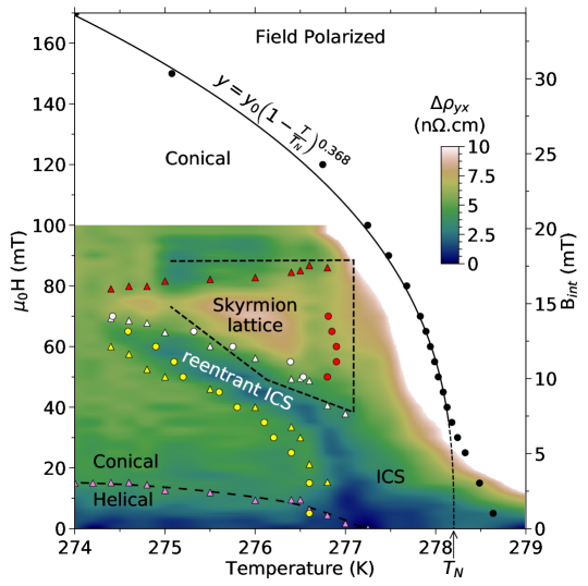
In Fig. 3.b, from 270 to K, is constant in temperature. This corresponds to the helical or conical states, at low or high magnetic fields respectively. Above K there is a large upturn corresponding to the transition to the paramagnetic or field polarized states. Around 276 K, we also observe a local maximum and minimum. The minimum is present from 5 to 65 mT, whereas the maximum is present in a narrower field range from 55 to 70 mT. The maximum and minimum observed in and are consistent in both locations and amplitudes, and have never been reported before. To gain further insights on their origin we combined and data sets in Fig. 4 to produce a color map (color maps made from either data sets are shown in the SI).
Skyrmion Topological Hall Effect
Fig. 4 shows that the local maximum occurs in a region of field and temperature, with a shape and location reminiscent of the skyrmion phase in MnSi. After accounting for demagnetizing effects (right axis of the H-T diagram) following the process of Ref. Ritz (2010) (see SI), this region corresponds quantitatively in field and temperature to the region where a skyrmion lattice has been observed in bulk crystals of FeGe by SANSMoskvin et al. (2013). We therefore conclude that this local maximum is the Topological Hall Effect induced by skyrmions magnetic texture. We note that this is the first report of a skyrmion Topological Hall Effect near room temperature.
The maximum amplitude of this THE is n.cm at 276 K, a value very similar to that of MnSiNeubauer et al. (2009b) at 29 K. This is contrary to what is expected from the small of FeGe produced by its larger skyrmions. However, is not the only factor determining the THE amplitude. The exact amplitude of the THE depends on the details of the band structure, but the THE is usually approximated asRitz et al. (2013); Neubauer et al. (2009b); Everschor-Sitte and Sitte (2014):
| (2) |
where is the local spin-polarization of the conduction electrons in the skyrmion state, is the effective magnetic field and is the ordinary Hall Effect constant. Here, we find (see methods) that in FeGe:
| (3) |
And this value is of the same order as the approximate THE value in MnSi:
| (4) |
We note that P is similar in both compounds, is 18 times smaller in FeGe than in MnSi, and is 6 times larger in FeGe than in MnSi. Overall, the THE amplitude estimated via Eqn. 2 is thus only three times smaller in FeGe than in MnSi.
Both THE values clearly overestimate the experimental values of the THE (n.cm in both MnSi and FeGe). This overestimation has been known for some time in MnSi and attributed to the factor Ritz et al. (2013). Recently, it was pointed out that this estimate is only an upper bound of skyrmions THEMaccariello et al. (2018). We also point out that the sign of the THE calculated using Eqn. 2 appears to be opposite to what is measured in MnSiNeubauer et al. (2009b). Recent theoretical effortsDenisov et al. (2017) show that a range of sign and amplitude is to be expected for the THE depending on coupling strength and electronic scattering rates. Looking beyond this ongoing debate, we note that at least the THE estimates for MnSi and FeGe are of the same order of magnitude in absolute value: 140 for MnSi and 45 for FeGe. Thus, this could explain why the experimental values of the THE are so similar in both compounds.
We also emphasize that the larger of FeGe appears to compensate the smaller . This means that the charge carrier density, and more generally the band structure, is a tool as important as skyrmions effective magnetic field in achieving measurable THE. For instance, in Pt/Co/Ir multilayer thin films, the skyrmion THE was estimated to be immeasurably small: as .m.T-1Maccariello et al. (2018). This value is more than 300 times smaller than the value .m.T-1 in FeGe, which suggest that FeGe is a compound of choice for the study of the THE near room temperature.
Signature of a Reentrant Helicoid Magnetic Phase
The local minimum observed in in Fig. 4, is new to all compounds with clear signatures of vortex-like cylindrical skyrmions. A positive THE has been observed in MnSiNeubauer et al. (2009b), and a negative THE was found in compounds such as Mn1-xFexSiFranz et al. (2014), but a positive and negative THE have never been observed consecutively, up to our knowledge.
Polycrystalline MnGe does show adjacent maximum and minimum in Kanazawa et al. (2016), but the amplitude of this effect is 50 times larger (n.cm) and spans over 10 Tesla and 100 Kelvin. Thus, this is very different from the phenomenon we observe in FeGe. In addition, the accepted interpretation of the behavior of MnGe does not involve cylindrical skyrmions but a spin structure periodic in all three dimensions undergoing a topological phase transition through the pair annihilation of hedgehogs and anti-hedgehogs topological spin singularitiesKanazawa et al. (2016).
In the curves of Fig. 3.a and the H-T diagram of Fig. 4, the local minimum tracks and ends with the lowest temperature of the skyrmions phase. But at higher temperatures it continues into the inhomogeneous chiral spin stateWilhelm et al. (2016) (ICS). Thus, the local minimum delimits a region which appears to compete with the skyrmion lattice phase but shares the signature of the helical and ICS states. Theoretical calculationsWilhelm et al. (2011) show that the hierarchy of close energy scales yields several possible magnetic phases in the vicinity of , including: + skyrmions, - skyrmions, half-skyrmions squares lattice and reentrant helicoid. The position of the local minimum in the phase diagram, bordering the skyrmion lattice phase, and its sign opposite to the THE of the skyrmion lattice, suggest + skyrmions with a positive effective magnetic field and negative THE; however, SANS does not show an other ordered skyrmion regionMoskvin et al. (2013). Thus, this suggests that the local minimum corresponds to a reentrant ICS or helicoid state. Such reentrant phase has never been observed before in skyrmion lattice systems, up to our knowledge. It also underscores the fact that, although magnetic and transport measurements show featuresWilhelm et al. (2011, 2016) at similar locations, the latter indicate a very different origin for the reentrant phase.
High Current Density Measurements of Hall Signatures
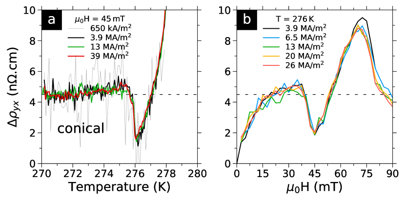
Hall Effect measurements in single crystals of MnSiSchulz et al. (2012) show a decrease in THE after skyrmions start to move at a critical current densities of MA/m2. Above this threshold, the amplitude of the THE is reduced from n.cm to n.cm as a result of the emerging electric field induced by moving skyrmionsSchulz et al. (2012). The value is sample dependent as measurements on MnSi nanowires showed MA/m2 Liang et al. (2015), and experiments using ultrasound to detect skyrmion movement found lower values kA/m2 in MnSi single crystalsLuo et al. (2017). In FeGe, the critical current density has only been measured by direct observation of skyrmion motion using TEM on a 100 nm thin lamella with kA/m2 at K.Yu et al. (2012)
In Fig. 5 we show for different current densities. At 45 mT, in Fig. 5.a, we show results outside the skyrmion area to test for Joule heating from the contacts or sample. At this field only the local minimum is present and no significant changes occur either in the position or amplitude of the minimum for current densities between 0.65 and 39 MA/m2. Close inspection of the data reveals a small 10 mK heating at 39 MA/m2 with respect to 3.9 MA/m2, indicating the absence of any significant heating. In Fig. 5.b, we show at 276 K for current densities ranging from 6.5 to 26 MA/m2. At this temperature, the field sweep encompasses several phases. Starting at low fields, one can see the change of curvature in corresponding to the helical phase below 15 mT, as well as the local minimum at 40 mT, and the THE caused by skyrmions at 75 mT. We observe no significant changes in neither of these signatures. Data at 3.9 MA/m2 might indicate a 0.5 n.cm increase of the THE peak at 75 mT with respect to higher current densities, but this is barely above noise level. Our experimental resolution of nV/ is insufficient to measure the THE below MA/m2 as in such a small sample (10m width) it translates to nV. Despite not seeing important changes, based on the results on FeGe lamellae, the current densities of our experiment most likely place skyrmions in a flow regime. Being in the flow regime implies that the THE of n.cm at 13 MA/m2 should increase at lower current densities. Therefore, FeGe would have a larger THE than that of MnSi in the skyrmion flow regime (n.cm).
Conclusions
We report the first unambiguous observation of a skyrmion lattice Topological Hall Effect near room temperature in bulk FeGe, using high resolution Hall Effect measurements in a mesoscopic FIB lamella extracted from a single crystal. The THE is present in a region of field and temperature close to , where a skyrmion lattice has been observed in bulk samples using SANSMoskvin et al. (2013). The amplitude of the THE is of the same magnitude as that of MnSi, and could be even larger at lower current densities. We argue that the large THE indicates that the smaller effective magnetic field produced by the bigger FeGe skyrmions is compensated by a larger ordinary Hall constant. We also report the signature of a reentrant magnetic phase adjacent to the skyrmion phase and connected to the helicoid or inhomogeneous chiral spin state, which confirms that the phase diagram in FeGe is more complex than that of a archetypal skyrmion compound like MnSi. Finally, FeGe THE magnitude is very similar to that of MnSi, but it is detected in conditions that are more suitable for applications, near room temperature (276 K) and at lower magnetic fields ( mT).
Methods
Crystal Growth
Cubic FeGe is a chiral stoichiometric binary B20 compound, crystallizing in the non-centrosymmetric cubic space group, isostructural to MnSi. Small single crystals ( µm wide) were grown by chemical vapor transport as described in Ref. Richardson (1967).
Nanofabrication
A lamella 0.75 µm thick, 10 µm wide and 25 µm long, was carved out of a pyramidal single crystal, using a FEI Helios 600 FIB/SEM. This lamella is shown in Figure.2.a. We used the known crystallographic orientation of pyramidal single crystals of FeGe, namely the [111] triangular facets with [110] edges, to align the cuts so that the lamella is perpendicular to the [100] axis and its edges are along [110] axes. The lamella was then laid flat on a custom chip, and electrical contacts were made using standard FIB platinum deposition. 2-wire contact resistances ranged from 33 for the current contacts, to 40 and 48 for voltage contacts, a significant part of which comes from the intrinsically high resistivity of the FIB deposited platinum (1-2 m.cm per the manufacturer). The result is a lamella for which the magnetic field is applied along [100] and the electrical current is flowing along [110].
Electrical Transport Measurements
We measured the longitudinal resistivity and the transverse or Hall resistivity in a Quantum Design PPMS with a 9 T vertical magnet, using a standard 4-wire procedure with a Linear-Research LR-700 AC resistance bridge functioning at a fixed frequency of 15.9 Hz. We used the same sign convention as in Ref. Neubauer et al. (2009b); Huang and Chien (2012); Porter et al. (2014), that is positive for electrons dominated transport. This combination of sample and setup achieved a noise level of nV/, which is close to the resolution limit of the instrument ( nV/) and the intrinsic Johnson-Nyquist noise of the resistive platinum contacts ( nV/). Considering measurement duration and current density (MA/m2), this translates into a noise level of typically less than 0.5 n.cm for the Hall resistivity , and 15 n.cm for , on a sample that is only µm3 in size.
The temperature dependence curves, , were measured by ramping up the temperature from 270 to 290 K for several applied magnetic fields, following a zero field cooled (ZFC) procedure. We used the standard magnetic field anti-symmetrization procedure to remove the experimental offset. The offset measured is equivalent to a misalignment of the contacts of µm. curves were measured by cooling in zero field to the target temperature, raising the magnetic field, and then measuring while stepping down the field to the opposite value. The field anti-symmetrization procedure was again used to remove the experimental offset. A complete hysteresis cycle was also measured at 276 K (see SI); compared to the curves, the only change in the initial ZFC ramp is an increase (from 15 to 30 mT) in the upper bound of the helical phase. An extension of the helical phase in magnetic field, has been observed in ZFC magnetization measurements in Fe and Co doped MnSiBauer et al. (2010).
Factors in the THE estimate
The polarization factor is , where is the ordered magnetic moment (spontaneous magnetization) in the skyrmion phase inferred from a linear extrapolation of the high-field data to H = 0 in an Arrott plot, and is the saturated moment deduced from the Curie-Weiss law in the paramagnetic state above Neubauer et al. (2009a). Ref. Porter et al. (2014) indicates that while Ref. Wilhelm et al. (2016) finds that at 276 K. We thus estimate the polarization factor in FeGe to be , very similar to the value 0.09 in MnSiRitz et al. (2013); Neubauer et al. (2009b).
The effective magnetic field induced by skyrmions magnetic texture isRitz et al. (2013); Neubauer et al. (2009b):
| (5) |
As the helical period of FeGe is nm just below Lebech et al. (1989), the corresponding effective magnetic field is T, which is 18 times smaller than T in MnSiRitz et al. (2013) ( nm).
Data Availability
The datasets generated during and/or analysed during the current study are available from the corresponding author on reasonable request.
Acknowledgements
B.M. and M.L. are grateful to M.B. Salamon, S.Z. Lin and C. Batista for fruitful discussions. C.R. thanks C.J.O. Reichhardt for a careful reading.
M.L., B.M and C.R. work was supported by the Laboratory Directed Research and Development program of Los Alamos National Laboratory under project number 20160369ER. This work was performed, in part, at the Center for Integrated Nanotechnologies, an Office of Science User Facility operated for the U.S. Department of Energy (DOE) Office of Science. Sandia National Laboratories is a multi-mission laboratory managed and operated by National Technology and Engineering Solutions of Sandia, LLC., a wholly owned subsidiary of Honeywell International, Inc., for the U.S. Department of Energy’s National Nuclear Security Administration under contract DE-NA-0003525. Los Alamos National Laboratory, an affirmative action equal opportunity employer, is operated by Los Alamos National Security, LLC, for the National Nuclear Security Administration of the U.S. Department of Energy under contract DE-AC52-06NA25396. M.J.S. and S.J. thank the support by NSF grant ECCS-1609585. M.J.S. also acknowledges support from the NSF Graduate Research Fellowship Program grant number DGE-1256259.
Author contributions
B.M., S.J. and M.L. planned the experiment. M.J.S and S.J. grew the material. M.L. and D.V.P. prepared the lamella. M.L. performed the measurements. M.L. and B.M. performed the data analysis. M.L., B.M. and C.R. wrote the manuscript and all authors contributed to the final version.
Competing financial interests
The authors declare no competing financial interests.
Materials & Correspondence
Correspondence should be addressed to Dr. Boris Maiorov (maiorov@lanl.gov). Materials request should be addressed to Dr. Song Jin (jin@chem.wisc.edu)
References
- Nagaosa and Tokura (2013) Naoto Nagaosa and Yoshinori Tokura, “Topological properties and dynamics of magnetic skyrmions,” Nature Nanotechnology 8, 899–911 (2013).
- Fert et al. (2017) Albert Fert, Nicolas Reyren, and Vincent Cros, “Magnetic skyrmions: advances in physics and potential applications,” Nature Reviews Materials 2, 17031 (2017).
- Fert et al. (2013) A Fert, V Cros, and J Sampaio, “Skyrmions on the track,” Nature Nanotechnology 8, 152–156 (2013).
- Finocchio et al. (2016) Giovanni Finocchio, Felix Büttner, Riccardo Tomasello, Mario Carpentieri, and Mathias Kläui, “Magnetic skyrmions: from fundamental to applications,” Journal of Physics D: Applied Physics 49, 423001 (2016).
- Liu and Li (2015) Ye-Hua Liu and You-Quan Li, “Dynamics of magnetic skyrmions,” Chinese Physics B 24, 017506 (2015).
- Belavin and Polyakov (1975) AA Belavin and AM Polyakov, “Metastable states of two-dimensional isotropic ferromagnets,” Journal of Experimental and Theoretical Physics Letters 22, 245–248 (1975).
- Bogdanov and Yablonskii (1989) AN Bogdanov and DA Yablonskii, “Thermodynamically stable “vortices” in magnetically ordered crystals. the mixed state of magnets,” Journal of Experimental and Theoretical Physics 95, 178 (1989).
- Rößler et al. (2006) U. K. Rößler, A. N. Bogdanov, and C. Pfleiderer, “Spontaneous skyrmion ground states in magnetic metals,” Nature 442, 797–801 (2006).
- Muhlbauer et al. (2009) S. Muhlbauer, B. Binz, F. Jonietz, C Pfleiderer, A Rosch, A Neubauer, Robert Georgii, and P. Boni, “Skyrmion Lattice in a Chiral Magnet,” Science 323, 915–919 (2009).
- Yu et al. (2011) X Z Yu, N Kanazawa, Y Onose, K Kimoto, W Z Zhang, S Ishiwata, Y Matsui, and Y Tokura, “Near room-temperature formation of a skyrmion crystal in thin-films of the helimagnet FeGe.” Nature materials 10, 106–109 (2011).
- Boulle et al. (2016) Olivier Boulle, Jan Vogel, Hongxin Yang, Stefania Pizzini, Dayane de Souza Chaves, Andrea Locatelli, Tevfik Onur Menteş, Alessandro Sala, Liliana D. Buda-Prejbeanu, Olivier Klein, Mohamed Belmeguenai, Yves Roussigné, Andrey Stashkevich, Salim Mourad Chérif, Lucia Aballe, Michael Foerster, Mairbek Chshiev, Stéphane Auffret, Ioan Mihai Miron, and Gilles Gaudin, Nature Nanotechnology 11, 449–454 (2016), 1601.02278 .
- Dzialoshinskii (1957) IE Dzialoshinskii, “Thermodynamic theory of weak ferromagnetism in antiferromagnetic substances,” Journal of Experimental and Theoretical Physics 5, 1259–1272 (1957).
- Moriya (1960) Tôru Moriya, “Anisotropic superexchange interaction and weak ferromagnetism,” Phys. Rev. 120, 91–98 (1960).
- Braun (2012) Hans-Benjamin Braun, “Topological effects in nanomagnetism: from superparamagnetism to chiral quantum solitons,” Advances in Physics 61, 1–116 (2012).
- Jonietz et al. (2011) F. Jonietz, S. Mulbauer, C. Pfleiderer, A. Neubauer, W. Munzer, A. Bauer, T. Adams, R. Georgii, P. Böni, R. A. Duine, K. Everschor, M. Garst, and A. Rosch, “Spin Transfer Torques in MnSi,” Science , 1648–1652 (2011).
- Schulz et al. (2012) T. Schulz, R. Ritz, A. Bauer, M. Halder, M. Wagner, C. Franz, C. Pfleiderer, K. Everschor, M. Garst, and A. Rosch, “Emergent electrodynamics of skyrmions in a chiral magnet,” Nature Physics 8, 301–304 (2012).
- Reichhardt et al. (2015) C. Reichhardt, D. Ray, and C. J. Olson Reichhardt, “Collective Transport Properties of Driven Skyrmions with Random Disorder,” Phys. Rev. Lett. 114, 217202 (2015).
- Iwasaki et al. (2013) Junichi Iwasaki, Masahito Mochizuki, and Naoto Nagaosa, “Current-induced skyrmion dynamics in constricted geometries,” Nature nanotechnology 8, 742–747 (2013).
- Zhang et al. (2015) Xichao Zhang, Motohiko Ezawa, and Yan Zhou, “Magnetic skyrmion logic gates: conversion, duplication and merging of skyrmions,” Scientific reports 5 (2015), 10.1038/srep09400.
- Jiang et al. (2015) Wanjun Jiang, Pramey Upadhyaya, Wei Zhang, Guoqiang Yu, M. Benjamin Jungfleisch, Frank Y. Fradin, John E. Pearson, Yaroslav Tserkovnyak, Kang L. Wang, Olle Heinonen, S. G. E. te Velthuis, and Axel Hoffmann, “Blowing magnetic skyrmion bubbles,” Science 349, 283–286 (2015).
- Büttner et al. (2015) Felix Büttner, C Moutafis, M Schneider, B Krüger, CM Günther, J Geilhufe, C v Korff Schmising, J Mohanty, B Pfau, S Schaffert, et al., “Dynamics and inertia of skyrmionic spin structures,” Nature Physics 11, 225–228 (2015).
- Woo et al. (2016) Seonghoon Woo, Kai Litzius, Benjamin Krüger, Mi-Young M-Y. Im, Lucas Caretta, Kornel Richter, Maxwell Mann, Andrea Krone, Robert M Reeve, Markus Weigand, Parnika Agrawal, Ivan Lemesh, M-A. Mohamad-Assaad Mawass, Peter Fischer, Mathias Kläui, and Geoffrey S D Beach, “Observation of room-temperature magnetic skyrmions and their current-driven dynamics in ultrathin metallic ferromagnets,” Nature Materials 15, 501–506 (2016).
- Juge et al. (2017) Roméo Juge, Soong-Geun Je, Dayane de Souza Chaves, Stefania Pizzini, Liliana D. Buda-Prejbeanu, Lucia Aballe, Michael Foerster, Andrea Locatelli, Tevfik Onur Menteş, Alessandro Sala, Francesco Maccherozzi, Sarnjeet S. Dhesi, Stéphane Auffret, Eric Gautier, Gilles Gaudin, Jan Vogel, and Olivier Boulle, “Magnetic skyrmions in confined geometries: Effect of the magnetic field and the disorder,” Journal of Magnetism and Magnetic Materials (2017), 10.1016/j.jmmm.2017.10.030.
- Maccariello et al. (2018) Davide Maccariello, William Legrand, Nicolas Reyren, Karin Garcia, Karim Bouzehouane, Sophie Collin, Vincent Cros, and Albert Fert, “Electrical detection of single magnetic skyrmions in metallic multilayers at room temperature,” Nature Nanotechnology 7, 056022 (2018).
- Neubauer et al. (2009a) A. Neubauer, C. Pfleiderer, B. Binz, A. Rosch, R. Ritz, P. G. Niklowitz, and P. Böni, “Topological Hall Effect in the Phase of MnSi,” Phys. Rev. Lett. 102, 186602 (2009a).
- Franz et al. (2014) C. Franz, F. Freimuth, A. Bauer, R. Ritz, C. Schnarr, C. Duvinage, T. Adams, S. Blügel, A. Rosch, Y. Mokrousov, and C. Pfleiderer, “Real-Space and Reciprocal-Space Berry Phases in the Hall Effect of ,” Phys. Rev. Lett. 112, 186601 (2014).
- Liang et al. (2015) Dong Liang, John P. DeGrave, Matthew J. Stolt, Yoshinori Tokura, and Song Jin, “Current-driven dynamics of skyrmions stabilized in MnSi nanowires revealed by topological Hall effect,” Nature Communications 6, 8217 (2015).
- Tokunaga et al. (2015) Y Tokunaga, X Z Yu, J S White, H. M. Rønnow, D Morikawa, Y Taguchi, and Y Tokura, “A new class of chiral materials hosting magnetic skyrmions beyond room temperature,” Nature Communications 6, 7638 (2015).
- Yu et al. (2017) Xiuzhen Yu, Daisuke Morikawa, Yusuke Tokunaga, Masashi Kubota, Takashi Kurumaji, Hiroshi Oike, Masao Nakamura, Fumitaka Kagawa, Yasujiro Taguchi, Taka hisa Arima, Masashi Kawasaki, Yoshinori Tokura, Taka hisa Arima, Masashi Kawasaki, Yoshinori Tokura, Taka hisa Arima, Masashi Kawasaki, and Yoshinori Tokura, “Current-Induced Nucleation and Annihilation of Magnetic Skyrmions at Room Temperature in a Chiral Magnet,” Advanced Materials (2017), 10.1002/adma.201606178.
- Yu et al. (2012) X.Z. Yu, N. Kanazawa, W.Z. Zhang, T. Nagai, T. Hara, K. Kimoto, Y. Matsui, Y. Onose, and Y. Tokura, “Skyrmion flow near room temperature in an ultralow current density,” Nature Communications 3, 988 (2012).
- McGrouther et al. (2016) D McGrouther, R J Lamb, M Krajnak, S McFadzean, S McVitie, R L Stamps, A O Leonov, A N Bogdanov, and Y Togawa, “Internal structure of hexagonal skyrmion lattices in cubic helimagnets,” New Journal of Physics 18 (2016), 10.1088/1367-2630/18/9/095004.
- Stolt et al. (2016) Matthew J. Stolt, Zi-An Li, Brandon Phillips, Dongsheng Song, Nitish Mathur, Rafal E. Dunin-Borkowski, and Song Jin, “Selective Chemical Vapor Deposition Growth of Cubic FeGe Nanowires That Support Stabilized Magnetic Skyrmions,” Nano Letters , acs.nanolett.6b04548 (2016).
- Moskvin et al. (2013) E. Moskvin, S. Grigoriev, V. Dyadkin, H. Eckerlebe, M. Baenitz, M. Schmidt, and H. Wilhelm, “Complex Chiral Modulations in FeGe Close to Magnetic Ordering,” Phys. Rev. Lett. 110, 077207 (2013).
- Wilhelm et al. (2011) H. Wilhelm, M. Baenitz, M. Schmidt, U. K. Rößler, A. A. Leonov, and A. N. Bogdanov, “Precursor Phenomena at the Magnetic Ordering of the Cubic Helimagnet FeGe,” Phys. Rev. Lett. 107, 127203 (2011).
- Cevey et al. (2013) L. Cevey, H. Wilhelm, M. Schmidt, and R. Lortz, “Thermodynamic investigations in the precursor region of FeGe,” Physica Status Solidi (B) Basic Research 250, 650–653 (2013).
- Turgut et al. (2017) Emrah Turgut, Matthew J Stolt, Song Jin, and Gregory D Fuchs, “Topological spin dynamics in cubic FeGe near room temperature,” (2017), arXiv:1705.03397 .
- Huang and Chien (2012) S. X. Huang and C. L. Chien, “Extended Skyrmion Phase in Epitaxial Thin Films,” Phys. Rev. Lett. 108, 267201 (2012).
- Porter et al. (2014) N. A. Porter, J. C. Gartside, and C. H. Marrows, “Scattering mechanisms in textured FeGe thin films: Magnetoresistance and the anomalous Hall effect,” Phys. Rev. B 90, 024403 (2014).
- Kanazawa et al. (2015) N. Kanazawa, M. Kubota, A. Tsukazaki, Y. Kozuka, K. S. Takahashi, M. Kawasaki, M. Ichikawa, F. Kagawa, and Y. Tokura, “Discretized topological Hall effect emerging from skyrmions in constricted geometry,” Phys. Rev. B 91, 041122 (2015).
- Zhang et al. (2017) S L Zhang, I Stasinopoulos, T Lancaster, F Xiao, A Bauer, F Rucker, A A Baker, A. I. Figueroa, Z. Salman, F. L. Pratt, S. J. Blundell, T. Prokscha, A. Suter, J. Waizner, M. Garst, D. Grundler, G. van der Laan, C. Pfleiderer, and T. Hesjedal, “Room-temperature helimagnetism in FeGe thin films,” Scientific Reports 7, 123 (2017).
- Meynell et al. (2014) S. A. Meynell, M. N. Wilson, J. C. Loudon, A. Spitzig, F. N. Rybakov, M. B. Johnson, and T. L. Monchesky, “Hall effect and transmission electron microscopy of epitaxial MnSi thin films,” Phys. Rev. B 90, 224419 (2014).
- Monchesky et al. (2014) T. L. Monchesky, J. C. Loudon, M. D. Robertson, and A. N. Bogdanov, “Comment on “Robust Formation of Skyrmions and Topological Hall Effect Anomaly in Epitaxial Thin Films of MnSi”,” Phys. Rev. Lett. 112, 059701 (2014).
- Wilhelm et al. (2016) H. Wilhelm, A. O. Leonov, U. K. Rößler, P. Burger, F. Hardy, C. Meingast, M. E. Gruner, W. Schnelle, M. Schmidt, and M. Baenitz, “Scaling study and thermodynamic properties of the cubic helimagnet FeGe,” Phys. Rev. B 94, 144424 (2016).
- Yeo et al. (2003) S. Yeo, S. Nakatsuji, A. D. Bianchi, P. Schlottmann, Z. Fisk, L. Balicas, P. A. Stampe, and R. J. Kennedy, “First-Order Transition from a Kondo Insulator to a Ferromagnetic Metal in Single Crystalline FeSi1-xGex,” Physical Review Letters 91, 046401 (2003).
- Pedrazzini et al. (2007) P. Pedrazzini, H. Wilhelm, D. Jaccard, T. Jarlborg, M. Schmidt, M. Hanfland, L. Akselrud, H. Q. Yuan, U. Schwarz, Yu. Grin, and F. Steglich, “Metallic State in Cubic FeGe Beyond Its Quantum Phase Transition,” Phys. Rev. Lett. 98, 047204 (2007).
- Neubauer et al. (2009b) A. Neubauer, C. Pfleiderer, B. Binz, A. Rosch, R. Ritz, P. G. Niklowitz, and P. Böni, “Topological Hall Effect in the Phase of MnSi,” Phys. Rev. Lett. 102, 186602 (2009b).
- Ritz (2010) R. Ritz, in Ph.D. Thesis, Superconductivity and non-Fermi liquid behavior on the border of itinerant ferromagnetism (2010) pp. 113–115.
- Ritz et al. (2013) R. Ritz, M. Halder, C. Franz, A. Bauer, M. Wagner, R. Bamler, A. Rosch, and C. Pfleiderer, “Giant generic topological Hall resistivity of MnSi under pressure,” Phys. Rev. B 87, 134424 (2013).
- Everschor-Sitte and Sitte (2014) Karin Everschor-Sitte and Matthias Sitte, “Real-space Berry phases: Skyrmion soccer (invited),” Journal of Applied Physics 115, 172602 (2014).
- Denisov et al. (2017) K. S. Denisov, I. V. Rozhansky, N. S. Averkiev, and E. Lähderanta, “A nontrivial crossover in topological Hall effect regimes,” Scientific Reports 7, 17204 (2017).
- Kanazawa et al. (2016) N. Kanazawa, Y. Nii, X. X. Zhang, A. S. Mishchenko, G. De Filippis, F. Kagawa, Y. Iwasa, N. Nagaosa, and Y. Tokura, “Critical phenomena of emergent magnetic monopoles in a chiral magnet,” Nature Communications 7, 11622 (2016).
- Luo et al. (2017) Yongkang Luo, Shizeng Lin, D. M. Fobes, M. Leroux, N. Wakeham, E. D. Bauer, J. B. Betts, J. D. Thompson, A. Miglior, M. Janoschek, and Boris Maiorov, “Depinning currents and elasticity of skyrmion lattice measured via Resonant Ultrasound Resonance,” arXiv x, XXX (2017).
- Richardson (1967) Marcus Richardson, “The Partial Equilibrium Diagram of the Fe-Ge System in the Range 40-72 at. % Ge, and the Crystallisation of some Iron Germanides by Chemical Transport Reactions.” Acta Chemica Scandinavica 21, 2305–2317 (1967).
- Bauer et al. (2010) A. Bauer, A. Neubauer, C. Franz, W. Münzer, M. Garst, and C. Pfleiderer, “Quantum phase transitions in single-crystal Mn1-xFexSi and Mn1-xCoxSi: Crystal growth, magnetization, ac susceptibility, and specific heat,” Physical Review B 82, 064404 (2010).
- Lebech et al. (1989) B Lebech, J Bernhard, and T Freltoft, “Magnetic structures of cubic FeGe studied by small-angle neutron scattering,” Journal of Physics: Condensed Matter 1, 6105–6122 (1989).