Directional amplifier in an optomechanical system with optical gain
Abstract
Directional amplifiers are crucial nonreciprocal devices in both classical and quantum information processing. Here we propose a scheme for realizing a directional amplifier between optical and microwave fields based on an optomechanical system with optical gain, where an active optical cavity and two passive microwave cavities are, respectively, coupled to a common mechanical resonator via radiation pressure. The two passive cavities are coupled via hopping interaction to facilitate the directional amplification between the active and passive cavities. We obtain the condition of achieving optical directional amplification and find that the direction of amplification can be controlled by the phase differences between the effective optomechanical couplings. The effects of the gain rate of the active cavity and the effective coupling strengths on the maximum gain of the amplifier are discussed. We show that the noise added to this amplifier can be greatly suppressed in the large cooperativity limit.
pacs:
I Introduction
The field of cavity optomechanics studies the nonlinear interaction between the electromagnetic cavity and mechanical resonator via radiation pressure Aspelmeyer1 ; Marquardt ; XiongH , where the effective optomechanical coupling strength can be greatly enhanced by driving the cavity with a strong pump field. By applying a pump field that is tuned to the lower motional sideband of the cavity field, optomechanics has witnessed great achievements such as ground-state cooling of the mechanical resonator Chan ; Teufel1 , optomechanically induced transparency Agarwal1 ; Weis ; Naeini1 , quantum state transfer Tian1 ; WangYD1 ; Andrews , and so on. Moreover, for the pump field that is tuned to the upper motional sideband of the cavity field, quantum entanglement Tian3 ; WangYD3 and microwave amplification Massel1 ; Korppi1 ; Korppi2 ; Toth have been investigated.
On the other hand, nonreciprocal elements such as isolators, circulators, and directional amplifiers play a crucial role in communication and quantum information processing. To achieve nonreciprocity, one need to break the time-reversal symmetry inherent in the governing electromagnetic-wave equations in linear and nonmagnetic media Potton . The traditional method to break the time-reversal symmetry is based on the magneto-optical effects (e.g., Farady rotation) Haldane ; Khanikaev ; Bi , which have the disadvantage of being bulky, costly, and unsuitable for on-chip integration. Recently, several alternative effects have been used to implement nonreciprocal optical devices, including dynamic spatiotemporal modulation of the refractive-index Lira ; Fang1 , angular momentum biasing in photonic or acoustic systems Fleury ; Estep ; WangDW , and optical nonlinearity FanL ; Chang ; GuoX . Furthermore, reconfigurable Josephson circulator and directional amplifier have been demonstrated in superconducting microwave circuit by a set of parametric pumps Sliwa ; Lecocq1 .
More recently, radiation-pressure-induced parametric coupling between cavity and mechanical modes in optomechanics has been exploited to break the time-reversal symmetry, leading to an intensive research in nonreciprocity based on optomechanical coupling Hafezi ; XuXW1 ; Metelmann1 ; ShenZ ; Tian2 ; Miri ; Peterson . Nonreciprocal devices including optomechanical isolators, circulators, and directional amplifiers have been proposed theoretically XuXW2 ; Malz and realized experimentally Ruesink ; Bernier ; Barzanjeh ; FangKJ ; ShenZ2 . Many of these works rely on controlling the relative phases of the pumps applied to the cavity modes to achieve nonreciprocity. Metelmann and Clerk have proposed a reservoir engineering approach for nonreciprocal transmission and amplification by modulating the interaction between the system and the dissipative reservoir Metelmann1 , and this approach has recently been applied to demonstrate the directional amplifier in an optomechanical crystal circuit FangKJ . Furthermore, it has been shown that directional amplification can be realized in a double-cavity optomechanical system with mechanical gain ZhangXZ or by introducing an additional mechanical drive LiY .
In this paper, we propose a scheme for realizing the directional amplifier between light fields with different frequencies (e.g. optical field and microwave field) in a triple-cavity optomechanical system with optical gain, where one cavity is doped with optical gain medium (i.e., active cavity) and the other two passive cavities are coupled to each other via hopping interaction, and the three single-mode cavities are coupled to a common mechanical resonator, respectively. This model is similar to that proposed in Ref. Tian2 , where nonreciprocal quantum-state conversion between microwave and optical photons was studied without including any gain medium. By introducing the optical gain, nonreciprocity has recently been observed in parity-time-symmetric (-symmetric) microcavities with balanced gain and loss Chang ; PengB ; LuoXB . Subsequently, optomechanical systems with optical gain have witnessed rapid progress, including phonon laser JingH1 ; HeB , optomechanically induced transparency JingH2 and all-optical photon transport switching DuL , -symmetry-breaking chaos LuXY , enhanced ground-state cooling of the mechanical resonator LiuYL , and enhanced sensitivity of detecting the mechanical motion LiuZP . Here we show that the optomechanical system with optical gain can operate as a directional amplifier between the active and passive cavities, where the direction of amplification can be controlled by adjusting the phase differences between the effective optomechanical couplings. Different from previous works Ruesink ; Malz ; ShenZ2 ; LiY , we find that the optical gain is the origin of amplification, instead of the blue-detuned optical pump fields Ruesink ; Malz ; ShenZ2 or additional mechanical drive LiY . Furthermore, the mechanical noise can be greatly suppressed by increasing the cooperativity associated with the active cavity. It is worth pointing out that no direct coupling is needed between the active and passive cavities in this optomechanical system. Therefore, directional amplification can be realized between two cavities with vastly different frequencies. For example, the active cavity is an optical cavity and the two passive cavities can be microwave cavities. Finally, we briefly discuss the group delay of the amplified field and find that it can be prolonged evidently compared to the case without optical gain.
The remainder of the paper is organized as follows. In Sec. II, we introduce the theoretical mode and derive the transmission matrix between the input and output operators. In Sec. III, we obtain the optimal condition for directional amplifier and study in detail the effects of phase difference, optical gain rate, and the effective coupling strength. Gain, gain-bandwidth product, and added noise are also discussed. In Sec. IV, we briefly investigate the group delay of the transmitted probe field. We finally summarize our work in Sec. V.
II Model
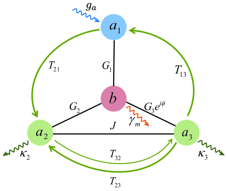
The optomechanical system under consideration is schematically shown in Fig. 1. Three cavity modes are coupled to a common mechanical mode via radiation pressure, respectively. Cavity can have vastly different frequency from that of cavities and , e.g., can be an optical microcavity and , are microwave cavities. Here we consider the cavity is an active cavity, which can be fabricated from doped silica and can emit photons in the 1550-nm band by optically pumping ions with a pump laser in the 1460-nm band PengB as an example. Furthermore, passive cavity is directly coupled to passive cavity via hopping interaction to facilitate the directional amplification between the active and passive cavities. We apply a strong driving field on each cavity mode to establish the parametric coupling. The Hamiltonian of this optomechanical system can be written as
| (1) | |||||
where is the annihilation (creation) operator of the cavity mode with resonance frequency , is the annihilation (creation) operator of the mechanical mode with resonance frequency , and is the single-photon optomechanical coupling strength between the cavity mode and the mechanical mode . The fourth term represents the interaction between the cavities and with being the coupling strength. The last term describes the coupling between the cavity modes and the driving fields with amplitude and frequency . We can write each operator for the cavity modes as the sum of its classical mean value and quantum fluctuation operator, i.e., , where the classical amplitude is determined by solving the classical equation of motion Barzanjeh . Further moving to the rotating frame with respect to , and neglecting the counter-rotating and higher-order terms with , we can obtain the following linearized Hamiltonian
| (2) | |||||
where () is the effective coupling strength between the mechanical mode and the cavity , and the phases of have been absorbed by redefining the operators and , and only the phase difference between them has physical effects. Here we have assumed that , , and .
According to the Heisenberg equations of motion and adding the corresponding damping and noise terms, we can get the following quantum Langevin equations (QLEs) Toth ; Bernier ; Barzanjeh
| (3) | |||||
| (4) | |||||
| (5) | |||||
| (6) |
where is the effective gain rate of cavity and is the gain which can be provided by pumping the ions in cavity Chang ; PengB ; the total decay rate of cavity is described by , where and are the external coupling rate and the intrinsic dissipation rates, respectively; is the damping rate of the mechanical mode . By introducing the Fourier transform of the operators
| (7) | |||
| (8) |
the zero-mean noise operators and associated with the gain in cavity obey Agarwal ; HeB ; Kepesidis ; LiuYL
| (9) |
Here we have assumed that the thermal photon occupation of cavity is zero because at optical frequencies, where is the Boltzmann constant and is the temperature of the environment.
Furthermore, the input field incident on the cavity via the external coupling satisfies the following correlation functions XuXW1 ; XuXW2 ; Agarwal4
| (10) |
where the term 1 results from the effect of vacuum noise and denotes the weak probe field incident on the cavity via the external coupling. The noise operators and correspond to the intrinsic dissipation of cavity and the damping of the mechanical resonator, respectively. Under the white noise assumption, the above zero-mean noise operators satisfy the nonzero correlation functions given by Toth ; Bernier ; Barzanjeh
| (11) |
Here the thermal photon occupations of the cavities are assumed to be zero under the condition that the reservoirs of the cavities are at sufficiently low temperature Aspelmeyer1 ; Malz ; Bernier , and the thermal phonon occupation of the mechanical resonator .
For convenience, the QLEs (4)-(6) can be written in the following matrix form
| (12) |
where the vector , with representing the transpose, the coefficient matrix
| (13) |
| (14) |
The system is stable only if the real parts of all the eigenvalues of matrix are negative. The stability condition can be derived by applying the Routh-Hurwitz criterion DeJesus ; Gradshteyn , whose general form is too cumbersome to give here. However, we will check numerically the stability condition in the following and choose the parameters in the stable regime. The solution to Eq. (12) in the frequency domain is
| (15) |
where represents the unitary matrix. Upon substituting Eq. (15) into the standard input-output relation , we can obtain
| (16) |
where the output field vector is the Fourier transform of , and the transmission matrix is given by
| (17) |
Here the matrix element () describes the transmission amplitude of the signal incident on the cavity and output from the cavity via the external coupling.
III Directional Amplifier
In this section, we consider how to realize the directional amplification between cavity modes and when an input probe field is resonant with the cavity frequency, i.e., . According to Eqs. (13) and (17), we can obtain the transmission matrix elements and as follows
| (18) | |||
| (19) |
where , , , and is the coupling efficiency for the cavity Barzanjeh ; Peterson ; Miri .
In order to realize the directional amplifier, we require e.g. that the probe field input from cavity can be amplified when it is transmitted from cavity , but the probe field input from cavity cannot be transmitted from cavity , i.e., and . We can get from Eqs. (18-19) that and if and , and we will show later that can be larger than 1 due to the optical gain of cavity . In addition, to prevent loss of the input field to other modes such as and , it is desirable that when . By choosing we can obtain that and Therefore, the conditions of directional amplification from cavity to cavity for an incident probe field with include
| (20) |
Under the above conditions, the transmission amplitude on resonance can be simplified as
| (21) | |||||
with the optomechanical cooperativity for . The effective gain rate can be controlled by tuning the gain rate and we can assume for simplicity. The gain of the amplifier is then given by Malz
| (22) |
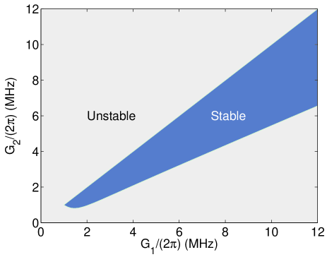
To realize the directional amplifier based on this optomechanical system with optical gain, the system should work in the stable regime. In Fig. 2, we plot the stability diagram with respect to the coupling strength and , where the parameters are given as MHz, MHz, , , , and . It can be seen that the system is stable only in a narrow regime due to the optical gain of cavity . Furthermore, when the coupling strength is larger than a critical value ( MHz), the system can be stable as long as the coupling strength is a little smaller than because we have chosen . Therefore, we can choose for a given to ensure the system is stable, where is the dimensionless value of in units of MHz.
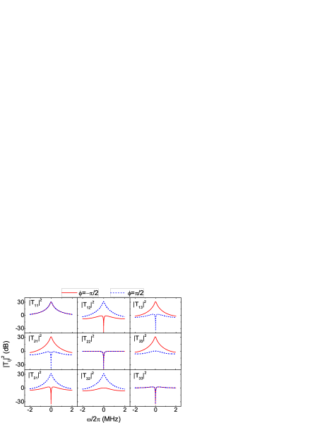
According to the transmission matrix, we can study the frequency and phase dependence of the transmission probabilities. Figure 3 plots the transmission probabilities between the cavities as a function of the probe detuning for phase difference and , respectively. When the phase difference is tuned to be , it can be seen that reaches the maximum value of about 30 dB (30 dB corresponds to ) but when . Therefore, the signal incident on cavity can be greatly amplified when it is transmitted from cavity , but the signal incident on cavity cannot be transmitted from cavity . This directional amplification arises due to interference between two possible paths, where one path is along , and the other path is along . When the phase difference , constructive interference between the two paths and the optical gain of cavity lead to the amplification for the optical transmission from cavity to cavity , but the opposite direction is forbidden due to destructive interference (). In addition, the signal input from cavity can be directionally amplified when it is transmitted from cavity with dB and . Consequently, directional amplifier can be realized based on this optomechanical system, and the input signal can be amplified directionally along the route . Furthermore, if we modulate the phase from to , the signal will be amplified along the opposite direction , which can be illustrated by changing the labels from to and altering the directions of all the arrows in Fig. 1.
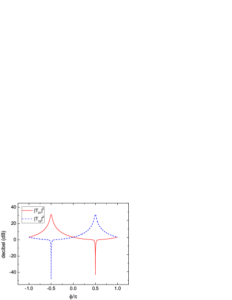
In what follows, we mainly consider the directional amplification between cavities and . In Fig. 4, we plot the transmission probabilities and as a function of the phase difference for . It can be seen that when and , therefore the Lorentz reciprocal theorem is satisfied and the response of this optomechanical system to the signal field is reciprocal. However, when ( is an integer), the time-reversal symmetry is broken, and the optomechanical system with optical gain exhibits a nonreciprocal response. In the regime , we have , but when . The optimal nonreciprocal response is obtained as [ dB and ] and [ dB and ] for the given parameters. Therefore, directional amplifier can be realized by modulating the phase difference .
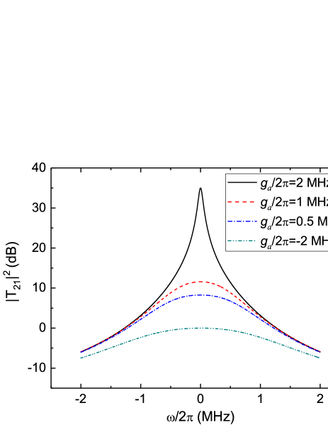
Next, we study the effect of the effective gain rate of cavity on the transmission probability . Figure 5 plots the transmission probability as a function of the probe detuning for different value of . When decreases from 2 MHz to 0.5 MHz, the maximum transmission probability on resonance decreases from about 35 dB to 8 dB with . Furthermore, if the active cavity becomes a passive cavity, i.e., MHz, the transmission probability on resonance , which indicates the appearance of optomechanically induced transparency Agarwal1 ; Weis . In this case, nonreciprocal transmission can still exist in this optomechanical system Tian2 , but the input probe field cannot be amplified. Therefore, the optical gain is the origin of amplification, and the phase difference is responsible for the nonreciprocal transmission in this optomechanical system.
III.1 Bandwidth and Gain-Bandwidth Product
For the phase-preserving linear amplifier, the bandwidth generally decreases with the increase of the gain, which can be seen from Fig. 5. The bandwidth of the amplifier can be approximately obtained according to the denominator of in Eq. (19). If we assume , then where we only keep the terms to the first order of Malz . The bandwidth is approximated by the smallest at which , and it can be given by
| (23) |
In this optomechanical system with optical gain, we can see from Fig. 2 that the system is unstable when the cooperativity is small. Therefore, we consider the large cooperativity limit, i.e. , then the bandwidth approaches resulting in the gain-bandwidth product
III.2 Added Noise
The added number of noise quanta of the amplifier can be obtained by calculating the output spectra of cavity , which is given by Malz ; Metelmann
| (24) | |||||
where we have used the noise correlation function in the frequency domain and the relation . It can be seen from Eq. (24) that output spectra of cavity contains eight components. If we consider the directional amplification of the signal incident on the cavity and output from the cavity via the external coupling, i.e., , then other transmission probabilities associated with thermal occupation can be treated as noise and we can assume . Therefore, the noise added to the amplifier is defined as CavesPRD ; ClerkRMP ; Nunnenkamp ; Malz . The general form of is too cumbersome to give here. However, if , , and , the noise added to the output of cavity can be given by
| (25) |
where we have assumed that the thermal photon occupations for the cavity modes and the thermal phonon occupation for the mechanical mode. The last term 1 on the right side of Eq. (25) results from the gain of cavity . We can see from Eq. (25) that the thermal noise from the mechanical resonator can be suppressed by increasing the cooperativity . For large and with a little larger than , we find at zero frequency .
.
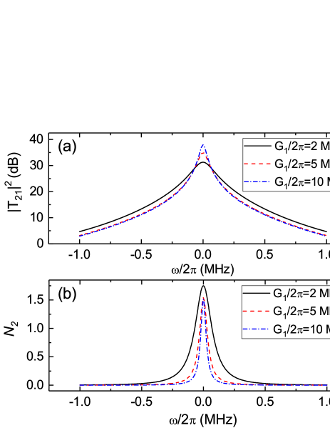
Figures 6(a) and 6(b) plot respectively the transmission probability and noise added to the cavity with respect to the probe detuning for different coupling strengths . It can be seen from Fig. 6(a) that the peak value of becomes larger when increases from to MHz. Furthermore, Fig. 6(b) shows that the added number of noise quanta decreases with increasing the optomechanical coupling constants and . In particular, when are large enough, thus and on resonance can approach to .
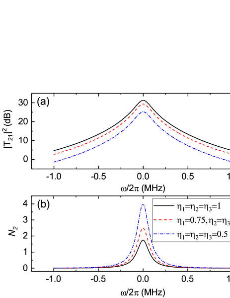
Furthermore, the influence of internal dissipation rate of the cavity on the gain and added noise of the amplifier is discussed in Fig. 7. We find that when the coupling efficiency reduced from 1 to 0.5 (critical coupling), the gain of the amplifier decreases, which can also be seen from Eq. (21). Meanwhile, Fig. 7(b) shows that the noise added to this amplifier becomes larger when the coupling efficiency reduces. Therefore, high coupling efficiency of each cavity is beneficial for enhancing the gain of the amplifier and suppressing the added noise.
IV Slow light effect
Finally, we study the slow light effect in the transmitted probe field. It is well known that the probe field within the electromagnetically induced transparency (EIT) window usually suffers a rapid phase dispersion, which can lead to the dramatic reduction in its group velocity. In optomechanical systems, this kind of slow light effects has been extensively investigated in the past decade Weis ; Naeini1 . Here we focus on the slow light effect associated with directional amplification. The optical group delay of the transmitted light is defined as Weis
| (26) |
where is the phase of the output field from cavity at the frequency of the probe field incident on cavity .
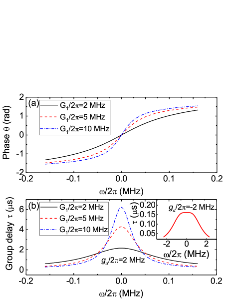
Figure 8 plots (a) phase and (b) group delay of the transmitted probe field from cavity for MHz, respectively. We can see from Fig. 8(a) that the amplified transmitted probe field is accompanied by rapid phase dispersion, and the slope of the phase dispersion around becomes larger when the coupling strength increases. Therefore, the maximum group delay is getting larger with increasing , as can be seen from Fig. 8(b). Furthermore, the inset of Fig. 8(b) shows the group delay with respect to the probe detuning when cavity is also the passive cavity. In this case, optomechanically induced transparency can occur in the probe field transmitted from cavity , as shown in Fig. 5. When MHz, we can see that the maximum group delay on resonance for the active cavity ( MHz) is about 4.3 s, while the maximum group delay for the passive cavity ( MHz) is about 0.16 s. Therefore, the optomechanical system with optical gain allows for directional amplification with prolonged group delay.
V Conclusion
In summary, we have investigated the directional amplifier in a hybrid optomechanical system with optical gain. The transmission between the active cavity and the passive cavity can be directionally amplified, and the direction of the amplification depends on the phase difference between the effective optomechanical couplings. The maximum amplifier gain can be enhanced by increasing the gain rate of the active cavity and the effective coupling strengths. In the large cooperativity limit, the effect of the mechanical noise can be significantly suppressed in the cavity outputs. Furthermore, the group delay of the transmitted probe field in this optomechanical system with optical gain can be improved up to one or two orders of magnitude compared to the optomechanical system without optical gain.
ACKNOWLEDGMENTS
This work is supported by the Science Challenge Project (under Grant No. TZ2018003), the National Key R&D Program of China grant 2016YFA0301200, the National Basic Research Program of China (under Grant No. 2014CB921403), and the National Natural Science Foundation of China (under Grants No. 11774024, No. 11534002, No. U1530401). C.J. is supported by the Natural Science Foundation of China (NSFC) under Grant No. 11304110, the Postdoctoral Science Foundation of China under Grant No. 2017M620593, and Qing Lan Project of Universities in Jiangsu Province.
References
- (1) M. Aspelmeyer, T. J. Kippenberg, and F. Marquardt, Cavity optomechanics, Rev. Mod. Phys. 86, 1391 (2014).
- (2) F. Marquardt and S. M. Girvin, Optomechanics, Physics 2, 40 (2009).
- (3) H. Xiong, L. G. Si, X. Y. Lü, X. X. Yang, and Ying Wu, Review of cavity optomechanics in the weak-coupling regime: from linearization to intrinsic nonlinear interactions, Sci. China Phys. Mech. Astron. 58, 1–13 (2015).
- (4) J. Chan, T. P. M. Alegre, A. H. Safavi-Naeini, J. T. Hill, A. Krause, S. Gröblacher, M. Aspelmeyer, and O. Painter, Laser cooling of a nanomechanical oscillator into its quantum ground state, Nature 478, 89 (2011).
- (5) J. D. Teufel, T. Donner, D. Li, J. W. Harlow, M. S. Allman, K. Cicak, A. J. Sirois, J. D. Whittaker, K. W. Lehnert, and R. W. Simmonds, Sideband cooling of micromechanical motion to the quantum ground state, Nature 475, 359–363 (2011).
- (6) G. S. Agarwal and S. Huang, Electromagnetically induced transparency in mechanical effects of light, Phys. Rev. A 81, 041803 (2010).
- (7) S. Weis, R. Rivière , S. Deléglise, E. Gavartin, O. Arcizet, A. Schliesser, and T. J. Kippenberg, Optomechanically induced transparency, Science 330, 1520 (2010).
- (8) A. H. Safavi-Naeini, T. P. Mayer Alegre, J. Chan, M. Eichenfield, M. Winger, Q. Lin, J. T.Hill, D. E. Chang, and O. Painter, Electromagnetically induced transparency and slow light with optomechanics, Nature 472, 69 (2011).
- (9) L. Tian, Adiabatic state conversion and pulse transmission in optomechanical systems, Phys. Rev. Lett. 108, 153604 (2012).
- (10) Y.-D. Wang and A. A. Clerk, Using interference for high fidelity quantum state transfer in optomechanics, Phys. Rev. Lett. 108, 153603 (2012).
- (11) R. W. Andrews, R. W. Peterson, T. P. Purdy, K. Cicak, R. W. Simmonds, C. A. Regal, and K. W. Lehnert, Bidirectional and efficient conversion between microwave and optical light, Nat. Phys. 10, 321–326 (2014).
- (12) L. Tian, Robust photon entanglement via quantum interference in optomechanical interfaces, Phys. Rev. Lett. 110, 233602 (2013).
- (13) Y.-D. Wang and A. A. Clerk, Reservoir-engineered entanglement in optomechanical Systems, Phys. Rev. Lett. 110, 253601 (2013).
- (14) F. Massel, T. T. Heikkilä, J.-M. Pirkkalainen, S. U. Cho, H. Saloniemi, P. J. Hakonen, and M. A. Sillanpää, Microwave amplification with nanomechanical resonators, Nature (London) 480, 351–354 (2011).
- (15) C. F. Ockeloen-Korppi, E. Damskägg, J.-M. Pirkkalainen, T. T. Heikkilä, F. Massel, and M. A. Sillanpää, Low-noise amplification and frequency conversion with a multiport microwave optomechanical device, Phys. Rev. X 6, 041024 (2016).
- (16) C. F. Ockeloen-Korppi, E. Damskägg, J.-M. Pirkkalainen, T. T. Heikkilä, F. Massel, and M. A. Sillanpää, Noiseless quantum measurement and squeezing of microwave fields utilizing mechanical vibrations, Phys. Rev. Lett. 118, 103601 (2017).
- (17) L. D. Tóth, N. R. Bernier, A. Nunnenkamp, A. K. Feofanov, and T. J. Kippenberg, A dissipative quantum reservoir for microwave light using a mechanical oscillator, Nat. Phys. 13, 787–793 (2017).
- (18) R. J. Potton, Reciprocity in optics, Rep. Prog. Phys. 67, 717 (2004).
- (19) F. D. M. Haldane and S. Raghu, Possible realization of directional optical waveguides in photonic crystals with broken time-reversal symmetry, Phys. Rev. Lett. 100, 013904 (2008).
- (20) A. B. Khanikaev, S. H. Mousavi, G. Shvets, and Y. S. Kivshar, One-way extraordinary optical transmission and nonreciprocal spoof plasmons, Phys. Rev. Lett. 105, 126804 (2010).
- (21) L. Bi, J. Hu, P. Jiang, D. H. Kim, G. F. Dionne, L. C. Kimerling, and C. A. Ross, On-chip optical isolation in monolithically integrated non-reciprocal optical resonators, Nat. Photon. 5, 758-762 (2011).
- (22) H. Lira, Z. Yu, S. Fan, and M. Lipson, Electrically driven nonreciprocity induced by interband photonic transition on a silicon chip, Phys. Rev. Lett. 109, 033901 (2012).
- (23) K. Fang, Z. Yu, and S. Fan, Photonic Aharonov-Bohm effect based on dynamic modulation, Phys. Rev. Lett. 108, 153901 (2012).
- (24) R. Fleury, D. L. Sounas, C. F. Sieck, M. R. Haberman, and A. Alù, Sound isolation and giant linear nonreciprocity in a compact acoustic circulator, Science 343, 516 (2014).
- (25) N. A. Estep, D. L. Sounas, J. Soric, and A. Alù, Magnetic-free non-reciprocity and isolation based on parametrically modulated coupled-resonator loops, Nat. Phys. 10, 923-927 (2014).
- (26) D.-W. Wang, H.-T. Zhou, M.-J. Guo, J.-X. Zhang, J. Evers, and S.-Y. Zhu, Optical diode made from a moving photonic crystal, Phys. Rev. Lett. 110, 093901 (2013).
- (27) L. Fan, J. Wang, L. T. Varghese, H. Shen, B. Niu, Y. Xuan, A. M. Weiner, and M. Qi, An all-silicon passive optical diode, Science 335, 447-450 (2012).
- (28) L. Chang, X. Jiang, S. Hua, C. Yang, J. Wen, L. Jiang, G. Li, G. Wang, and Min Xiao, Parity-time symmetry and variable optical isolation in active-passive-coupled microresonators, Nat. Photon. 8, 524-529 (2014).
- (29) X. Guo, C.-L. Zou, H. Jung, and H. X. Tang, On-chip strong coupling and efficient frequency conversion between telecom and visible optical modes, Phys. Rev. Lett. 117, 123902 (2016).
- (30) K. M. Sliwa, M. Hatridge, A. Narla, S. Shankar, L. Frunzio, R. J. Schoelkopf, and M. H. Devoret, Reconfigurable Josephson circulator/directional amplifier, Phys. Rev. X 5, 041020 (2015).
- (31) F. Lecocq, L. Ranzani, G. A. Peterson, K. Cicak, R. W. Simmonds, J.D. Teufel, and J. Aumentado, Nonreciprocal microwave signal processing with a field-programmable Josephson amplifier, Phys. Rev. Appl. 7, 024028 (2017).
- (32) M. Hafezi and P. Rabl, Optomechanically induced non-reciprocity in microring resonators, Opt. Express 20, 7672-7684 (2012).
- (33) X.-W. Xu and Y. Li, Optical nonreciprocity and optomechanical circulator in three-mode optomechanical systems, Phys. Rev. A 91, 053854 (2015).
- (34) A. Metelmann and A. A. Clerk, Nonreciprocal photon transmission and amplification via reservoir engineering, Phys. Rev. X 5, 021025 (2015).
- (35) Z. Shen, Y.-L. Zhang, Y. Chen, C.-L. Zou, Y.-F. Xiao, X.-B. Zou, F.-W. Sun, G.-C. Guo, and C.-H. Dong, Experimental realization of optomechanically induced non-reciprocity, Nat. Photonics 10, 657 (2016).
- (36) L. Tian and Z. Li, Nonreciprocal quantum-state conversion between microwave and optical photons, Phys. Rev. A 96, 013808 (2017).
- (37) M.-A. Miri, F. Ruesink, E. Verhagen, and A. Alù, Optical nonreciprocity based on optomechanical coupling, Phys. Rev. Appl. 7, 064014 (2017).
- (38) G. A. Peterson, F. Lecocq, K. Cicak, R. W. Simmonds, J. Aumentado, and J. D. Teufel, Demonstration of efficient nonreciprocity in a microwave optomechanical circuit, Phys. Rev. X 7, 031001 (2017).
- (39) X.-W. Xu, Y. Li, A.-X. Chen, and Y.-x. Liu, Nonreciprocal conversion between microwave and optical photons in electro-optomechanical systems, Phys. Rev. A 93, 023827 (2016).
- (40) D. Malz, L. D. Tóth, N. R. Bernier, A. K. Feofanov, T. J. Kippenberg, A. Nunnenkamp, Quantum-limited directional amplifiers with optomechanics, Phys. Rev. Lett. 120, 023601 (2018).
- (41) F. Ruesink, M.-A. Miri, A. Alù, and E. Verhagen, Nonreciprocity and magnetic-free isolation based on optomechanical interactions, Nat. Commun. 7, 13662 (2016).
- (42) N. R. Bernier, L. D. Tóth, A. Koottandavida, M. A. Ioannou, D. Malz, A. Nunnenkamp, A. K. Feofanov, and T. J. Kippenberg, Nonreciprocal reconfigurable microwave optomechanical circuit, Nat. Commun. 8, 604 (2017).
- (43) S. Barzanjeh, M. Wulf, M. Peruzzo, M. Kalaee, P. B. Dieterle, O. Painter, and J. M. Fink, Mechanical on-chip microwave circulator, Nat. Commun. 8, 953 (2017).
- (44) K. Fang, J. Luo, A. Metelmann, M. H. Matheny, F. Marquardt, A. A. Clerk, and O. Painter, Generalized non-reciprocity in an optomechanical circuit via synthetic magnetism and reservoir engineering, Nat. Phys. 13, 465-471 (2017).
- (45) Z. Shen, Y.-L. Zhang, Y. Chen, F.-W. Sun, X.-B. Zou, G.-C. Guo, C.-L. Zou, C.-H. Dong, Reconfigurable optomechanical circulator and directional amplifier, arXiv: 1709.06236.
- (46) X. Z. Zhang, L. Tian, Y. Li, Optomechanical transistor with mechanical gain, Phys. Rev. A 97, 043818 (2018).
- (47) Y. Li, Y. Y. Huang, X. Z. Zhang, and L. Tian, Optical directional amplification in a three-mode optomechanical system, Opt. Express 25, 18907–18916 (2017).
- (48) B. Peng, Ş. K. Özdemir, F. Lei, F. Monifi, M. Gianfreda, G. L. Long, S. Fan, F. Nori, C. M. Bender, and L. Yang, Parity-time-symmetric whispering-gallery microcavities, Nat. Phys. 10, 394-398 (2014).
- (49) X. B. Luo, J. H. Huang, H. H. Zhong, X. Z. Qin, Q. T. Xie, Y. S. Kivshar, and C. H. Lee, Pseudo-Parity-Time symmetry in optical systems, Phys. Rev. Lett. 110, 243902 (2013).
- (50) H. Jing, S. K. Özdemir, X.-Y. Lü, J. Zhang, L. Yang, and F. Nori, -symmetric phonon laser, Phys. Rev. Lett. 113, 053604 (2014).
- (51) B. He, L. Yang, and M. Xiao, Dynamical phonon laser in coupled active-passive microresonators, Phys. Rev. A 94, 031802 (2016).
- (52) H. Jing, S. K. Özdemir, Z. Geng, J. Zhang, X.-Y. Lü, B. Peng, L. Yang, and F. Nori, Optomechanically-induced transparency in parity-time-symmetric microresonators, Sci. Rep. 5, 9663 (2015).
- (53) L. Du, Y.-M. Liu, Y. Zhang, and J.-H. Wu, All-optical photon transport switching in a passive-active optomechanical system, arXiv: 1801.02296.
- (54) X.-Y. Lü, H. Jing, J.-Y. Ma, and Y. Wu, -symmetry-breaking chaos in optomechanics, Phys. Rev. Lett. 114, 253601 (2015).
- (55) Y.-L. Liu and Y.-x. Liu, Energy-localization-enhanced ground-state cooling of a mechanical resonator from room temperature in optomechanics using a gain cavity, Phys. Rev. A 96, 023812 (2017).
- (56) Z.-P. Liu, J. Zhang, S. K. Özdemir, B. Peng, H. Jing, X.-Y. Lü, C.-W. Li, L. Yang, F. Nori, and Y.-x. Liu, Metrology with -symmetric cavities: enhanced sensitivity near the -phase transition, Phys. Rev. Lett. 117, 110802 (2016).
- (57) G. S. Agarwal and K. Qu, Spontaneous generation of photons in transmission of quantum fields in -symmetric optical systems, Phys. Rev. A 85, 031802 (2012).
- (58) K. V. Kepesidis, T. J. Milburn, J. Huber, K. G. Makris, S. Rotter, and P. Rabl, -symmetry breaking in the steady state of microscopic gain-loss systems, New J. Phys. 18, 095003 (2016).
- (59) G. S. Agarwal and S. Huang, Optomechanical systems as single-photon routers, Phys. Rev. A 85, 021801 (2012).
- (60) E. X. DeJesus and C. Kaufman, Routh-Hurwitz criterion in the examination of eigenvalues of a system of nonlinear ordinary differential equations, Phys. Rev. A 35, 5288 (1987).
- (61) I. S. Gradshteyn and I. M. Ryzhik, in Table of Integrals, Series and Products (Academic, 1980), p. 1119.
- (62) A. Metelmann and A. A. Clerk, Quantum-limited amplification via reservoir engineering, Phys. Rev. Lett. 112, 133904 (2014).
- (63) C. M. Caves, Quantum limits on noise in linear amplifiers, Phys. Rev. D 26, 1817 (1982).
- (64) A. A. Clerk, M. H. Devoret, S. M. Girvin, Florian Marquardt, and R. J. Schoelkopf, Introduction to quantum noise, measurement, and amplification, Rev. Mod. Phys. 82, 1155 (2010).
- (65) A. Nunnenkamp, V. Sudhir, A.K. Feofanov, A. Roulet, and T.J. Kippenberg, Quantum-limited amplification and parametric instability in the reversed dissipation regime of cavity optomechanics, Phys. Rev. Lett. 113, 023604 (2014).