PAM: When Overloaded, Push Your Neighbor Aside!
1. Introduction
Network Function Virtualization (NFV) enables efficient development and management of network functions (NFs) by replacing dedicated middleboxes with virtualized Network Functions (vNFs). When a vNF is overloaded, network operators can easily scale it out by creating a new vNF instance and balancing the load between two instances. Meanwhile, network operators usually require packets to be processed by multiple vNFs in a certain sequence, which is referred to as a service chain (Kumar et al., 2015). However, the introduction of NFV results in high latency. Virtualization techniques in NFV significantly increase processing latency (Sun et al., 2017). To address this problem, many research efforts from both industry (Netronome, 2018) and academic communities (Le et al., 2017) introduce programmable Network Interface Cards based on Network Processing Units (NPUs), i.e. SmartNICs, to accelerate NFV. With the advantage of high performance and resource efficiency, offloading vNFs from CPU to SmartNIC brings significant performance benefits.


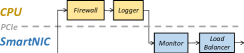
Meanwhile, as the network traffic fluctuates, NFs on SmartNIC can also be overloaded (Le et al., 2017). If we naively refer to the scaling out solutions for CPU, we have to introduce one more SmartNIC to alleviate the hot spot, which is hardly possible since each server is usually equipped with one or two SmartNICs only. UNO (Le et al., 2017) proposed to alleviate the overload situation by identifying the bottleneck vNF with minimum processing capacity and migrating it to CPU. However, this intuitive naive solution may increase the latency of the service chain. As shown in Figure 1(b), if Monitor is the bottleneck vNF and we migrate it to CPU, packets have to be transmitted over PCIe for two more times. This adds tens of microseconds latency according to our experiments, which may be unacceptable for latency-sensitive applications (Sun et al., 2017).
To address this problem, in this poster, we propose PAM, the Push Aside Migration scheme, which identifies the right vNFs to migrate to alleviate the hot spot on SmartNIC without introducing long-term performance degradation. We consider from the scope of the entire service chain and propose our key observation that when a vNF is overloaded, we can migrate other vNFs on the SmartNIC away to release resources for the overloaded vNF. To avoid introducing extra packet transmissions over PCIe, we choose to migrate vNFs on the border of SmartNIC and CPU. As shown in Figure 1(c), we migrate the Logger to CPU to alleviate the Monitor hot spot. However, selecting the right border vNFs for migration is challenging. Migrating too few vNFs may not effectively alleviate the hot spot, while migrating too many vNFs may waste CPU resource. To address this challenge, PAM carefully models SmartNIC and CPU resources and proposes an effective algorithm to find the most suitable vNFs for migration. Our evaluation shows that PAM could effectively alleviate the hot spot on SmartNIC and generate a service chain with 18% lower latency compared with the naive solution.
2. PAM Design
In this section, we first introduce the resource constraints of SmartNIC and CPU. We then introduce how PAM identifies proper border elements on SmartNIC for migration to effectively alleviate the hot spots on SmartNIC without performance degradation due to extra packet transmissions.
To understand the resource constraints of the CPU and SmartNIC, we refer to (Meng et al., 2018) and assume that the resource utilization of a vNF on both SmartNIC and CPU increases linearly with the vNF throughput. Suppose the throughput capacity of vNF on SmartNIC is and the current throughput is , the ratio of consumed resource on SmartNIC is . We measure and present the capacity of several vNFs in Table 1. We adopt the NF migration mechanism between SmartNIC and CPU introduced in (Le et al., 2017). The network administrators can periodically query the load of SmartNIC and CPU and execute the PAM border vNF selection algorithm:
| vNF | Firewall | Logger | Monitor | Load Balancer |
| 10 Gbps | 2 Gbps | 3.2 Gbps | 10 Gbps | |
| 4 Gbps | 4 Gbps | 10 Gbps | 4 Gbps |
Step 1: Border vNFs Identification. We first find out the border vNFs of SmartNIC. We classify them into left border and right border vNFs, whose upstream or downstream vNF is placed on CPU. For example, the left border vNF in Figure 1(a) is Logger and the right border vNF is Firewall. Due to the several packet transmissions between SmartNIC and CPU, there may be multiple border vNFs in a service chain. We respectively denote them as set and . Migrating border vNFs will not introduce new packet transmissions.
Step 2: Migration vNF Selection. To alleviate the overload with minimum number of vNF to migrate, we select the vNF from border vNFs with minimum capacity on SmartNIC:
| (1) |
Step 3: Overload Alleviation Check. Meanwhile, we need to ensure migration will not cause new hot spots on CPU, and the overload of SmartNIC can be alleviated. For :
| (2) |
If Equation 2 is not satisfied, which indicates migration will create new hot spots on CPU, we cannot migrate it to CPU. We remove from or and go back to Step 2. Otherwise, we can continue to check constraint :
| (3) |
The algorithm terminates if Equation 3 is satisfied. Otherwise, we migrate to CPU. If , we remove it from and add its downstream element into the set if the downstream element is also placed on SmartNIC. If , we execute similar actions on its upstream element. We then go back to Step 2 to continue the loop. If both CPU and SmartNIC are overloaded, which rarely happens, the network operator must start another instance to alleviate the hot spot (Gember-Jacobson et al., 2014).
3. Preliminary Evaluation
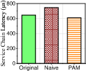
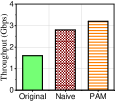
We implement the service chain in Figure 1 on a server equipped with one Netronome Agilio CX 210GbE SmartNIC (Netronome, 2018), two Intel Xeon E5-2620 v2 CPUs (2.10 GHz, 6 physical cores), and 128G RAM. For the naive algorithm, we pick the vNF on SmartNIC with minimal capacity . We measure the service chain throughput and latency of different migration selection mechanisms in Figure 1. We vary the packet size from 64B to 1500B with a DPDK packet sender (Intel, 2018) and present the average latency and throughput in Figure 2.
PAM decreases the service chain latency by 18% on average compared to the naive solution. The service chain latency with PAM is almost unchanged compared to the latency before migration because PAM does not introduce redundant packet transmissions. Meanwhile, the throughput of the service chain of PAM is improved a little since NFs may perform differently on SmartNIC and CPU.
4. Conclusion and Future Work
We have proposed a vNF selection scheme, PAM, which reduces the service chain latency when alleviating hot spots on SmartNIC. We present our key novelty of pushing the border vNFs aside to release resources for the bottleneck vNF. Evaluation shows that PAM could alleviate the hot spot on SmartNIC and generate a service chain with 18% lower latency compared with the naive solution. As our future work, we will analyze PCIe transmissions in detail, consider the difference of processing the same vNF on both devices, and extend PAM to work in FPGA-based SmartNICs.
References
- (1)
- Gember-Jacobson et al. (2014) Aaron Gember-Jacobson, Raajay Viswanathan, Chaithan Prakash, Robert Grandl, Junaid Khalid, Sourav Das, and Aditya Akella. 2014. OpenNF: Enabling innovation in network function control. In Proceedings of the Conference of the ACM Special Interest Group on Data Communication (SIGCOMM’14). ACM, 163–174.
- Intel (2018) DPDK Intel. 2018. Data Plane Development Kit. http://dpdk.org
- Kumar et al. (2015) S Kumar, M Tufail, S Majee, C Captari, and S Homma. 2015. Service function chaining use cases in data centers. IETF SFC WG (2015).
- Le et al. (2017) Yanfang Le, Hyunseok Chang, Sarit Mukherjee, Limin Wang, Aditya Akella, Michael M Swift, and TV Lakshman. 2017. UNO: uniflying host and smart NIC offload for flexible packet processing. In Proceedings of the 2017 Symposium on Cloud Computing (SoCC’17). ACM, 506–519.
- Meng et al. (2018) Zili Meng, Jun Bi, Chen Sun, Haiping Wang, and Hongxin Hu. 2018. CoCo: Compact and Optimized Consolidation of Modularized Service Function Chains in NFV. In Proceedings of the 2018 International Conference on Communications (ICC’18). IEEE.
- Netronome (2018) Netronome. 2018. Netronome Agilio CX Dual-Port 10 Gigabit Ethernet SmartNIC. http://www.colfaxdirect.com/store/pc/viewPrd.asp?idproduct=3017
- Sun et al. (2017) Chen Sun, Jun Bi, Zhilong Zheng, Heng Yu, and Hongxin Hu. 2017. NFP: Enabling Network Function Parallelism in NFV. In Proceedings of the Conference of the ACM Special Interest Group on Data Communication (SIGCOMM’17). ACM, 43–56.