Influence of plasma background on 3D scrape-off layer filaments
Abstract
This paper presents the effect of self-consistent plasma backgrounds including plasma-neutral interactions, on the dynamics of filament propagation. The principle focus is on the influence of the neutrals on the filament through both direct interactions and through their influence on the plasma background. Both direct and indirect interactions influence the motion of filaments. A monotonic increase of filament peak velocity with upstream electron temperature is observed, while a decrease with increasing electron density is observed. If ordered by the target temperature, the density dependence disappears and the filament velocity is only a function of the target temperature. Smaller filaments keep a density dependence, as a result of the density dependence of the plasma viscosity. The critical size , where filaments are fastest, is shifted to larger sizes for higher densities, due to the plasma viscosity. If the density dependence of the plasma viscosity is removed, has no temperature dependence, but rather a density dependence.
-
June 2018
1 Introduction
Filaments are field-aligned non-linear pressure perturbations that have been observed in most magnetized plasmas [1]. These intermittent, localized objects have a much smaller cross-section perpendicular to the magnetic field than parallel. In tokamaks they can carry a significant amount of heat and particles to the first wall materials, which may cause sputtering, thereby diluting the plasma and degrading the wall. The plasma wall interaction can cause dust production as well as increase tritium retention, both concerns for ITER [2]. Further filaments contribute to the cross field transport in the scrape-off layer (SOL), which influences the width of the SOL and affects the power handling at the diveror [3, 4, ?]. Understanding filaments with a view to predicting and controlling them in future devices is therefore of interest.
Computer simulation of filaments were done initially in two dimensions [5, 6, 7]. In 2D simulations closures are needed due to the lack of resolution in the parallel direction. The two commonly used closures are sheath dissipation closure, neglecting parallel gradients, or the vorticity advection closure, neglecting parallel currents. Both cannot reproduce the results from full 3D simulation [8]. Boltzmann spinning and the associated poloidal motion is also not observed with 2D closures [8]. Further drift waves cannot be captured properly by 2D simulation [9]. Going towards a more complete picture of the physics, the complexity of simulations was further increased. For example finite thermal perturbation can significantly influence filament dynamics, as it increases the poloidal motion and decreases the radial velocity [10]. For a more complete review of both the computational advances, as well as experimental observations, see the review given in [1].
Neutral plasma interactions are important for the operation of fusion devices, in particular for detached operation, where neutrals dissipate the majority of the parallel heat fluxes in the divertor region. Also in the attached regime, neutrals can have a significant influence on plasma dynamics. Compared to present day machines, future fusion devices will have an increased density in the divertor. This further increases the importance of understanding the influence of neutral plasma interactions in the divertor. Plasma wall interaction are a main issue, not only for the operation of ITER, but also for future fusion devices. Therefore increasing the understanding of filaments, one of the main transport mechanisms in the SOL is needed, especially in the presence of neutrals. Plasma turbulence interactions with neutrals studies have recently been conducted [11, 12, 13]. Leddy et al [11] show that the neutral interaction can be increased by resolving the fluctuations, compared to the mean field approach. Bisai and Kaw [12] show that neutrals can reduce electric fields, reduce fluctuations and increase pressure gradients in the SOL. In terms of filament neutral interaction, a recent study showed that filaments can significantly increase the fuelling of the core by creating energetic neutrals [14]. Scaling laws, describing the filaments radial velocity as a function of plasma background parameter, have been derived [7, 10, 6]. The scalings neglect not only neutral plasma interactions, but simplify the equations in further ways, to get an analytical expression for the filament velocity.
The study presented here extends this by taking not only the plasma neutral interaction into account, but further looking at self consistent parallel background profiles which include parallel gradients. By looking at both direct and indirect interactions between filaments and the neutral population, these simulation extend the earlier study of direct interactions [15]. By looking at the influence of background profiles, earlier studies looking at the influence of resistivity are extended in a self consistent way [16].
The equations and the setup used here are described in section 2, followed by a short introduction to the background profiles in section 3. The 3D dynamics of the simulated filaments is discussed in section 4. This is followed by the influence of the neutrals, the background profiles in general, and the filament size in section 5, before the summary in section 6.
2 Modelling setup
The model is based on the STORM module [8, 16, 10, 15], using BOUT++ [17, 18]. In this section we first discuss the simplified 3D straight field line SOL geometry and then we present the drift ordered fluid equations.
The direction along the magnetic field is denoted by . The target is at , where sheath boundary conditions are enforced. Due to the symmetry of the system, only half of the domain is simulated, namely . At symmetry boundary conditions are applied.
In addition to the parallel direction, the domain is spanned by the radial direction denoted by and the bi-normal direction, denoted by . The length along the magnetic field is m, and is resolved by grid points. In the perpendicular direction the length are i.e. dependent on the perpendicular extent of the filament . The resolution is . For mm this gives a grid spacing if mm. The filament size of mm was chosen, as it is both close to the critical size (introduced later), but also similar to the size experimentally observed in MAST[15, 10].
The STORM model is a drift ordered full fluid model, following the approach of Simakov and Catto [19, 20]. The equations are given in Bohm units [10]. The time is normalized using the ion gyro frequency , lengths with the gyro radius and speeds with the speed of sound .
The model consists of the electron density continuity equation
| (1) | ||||
| with the potential being the Laplacian inversion of the vorticity. is the magnitude of the magnetic field, and is its direction. is the diffusion coefficient for the electron density. The terms with are terms due to curvature, which are artificially reintroduced, to drive the filaments. is related to the radius of curvature as m-1. , and are the ionization, recombination and charge exchange rates. The equation for the parallel electron velocity is | ||||
| (2) | ||||
| with the ion-electron mass ratio is . The parallel ion-electron resistivity is given by . The equation for the parallel ion velocity | ||||
| (3) | ||||
| the equation for the electron temperature | ||||
| (4) | ||||
| The parallel heat conduction is given by and is the perpendicular heat transport coefficient. The equation for the vorticity is | ||||
| (5) | ||||
| with the vorticity diffusion coefficient . The equation for the neutral density is | ||||
| (6) | ||||
The diffusion constants, resistivity and neutral rates are calculated self consistently [10]. In the equation for the neutral density, is the neutral diffusion, given by
| (7) | ||||
| (8) |
with deuterium’s thermal speed at 300 K and the atomic deuterium-deuterium cross section pm. The diffusion limiter is needed to compensate for the lack of pressure in high neutral density regions, in which case an unphysically high diffusion occurs. The term emulates cross field losses. Recycling of the neutrals is proportional to the particle flux at the target , the recycling coefficient and depends on a Gaussian recycling falloff length m:
| (9) |
where is a normalization constant, ensuring that a fraction of the target flux are recycled along the field line. This non-local model was chosen, as the lack of pressure combined with high neutral densities near the target results in low return fluxes of particles back along the field line. This non-local recycling model combined with a limiter for the neutral diffusion ensures that the neutral are transported from the target up stream. The recycling model is an extension of the density source previously used in STORM [8, 16, 10].
In the radial direction Neumann boundary conditions with zero gradient are enforced, with the exception of and , which are set to respective background values. The direction is periodic for all quantities. At the symmetry plane the velocities and are set to zero, whereas for the other quantities zero gradients are enforced. At the target magnetic pre-sheath boundary conditions were set. The ions need to reach the speed of sound , and the electrons have to reach at the sheath boundary
| (10) |
where is the floating potential [21, 22]. The neutral density is forced to have a vanishing gradient at the target boundary.
3 Background profiles
In order to study the influence of self consistent backgrounds on filaments, a procedure for producing such backgrounds is needed. Filaments will be seeded on these backgrounds, as described in section 4. The backgrounds are an extension of the two-point model. They feature only dependence along the magnetic field, and not in the radial direction. In order to generate the one dimensional background profiles, the equations presented above were used, with the perpendicular terms dropped and the current forced to be zero. The particle and energy influx was set to an exponential shape, to localize the influx at the mid-plane. The magnitude was controlled with an PID-controller to achieve a predefined value for upstream temperature and density. A PID controller sets the influx as a function of the instantaneous difference to the predefined value, the integral and the derivative of the difference. It is a commonly used control loop feedback mechanism. For the 3D simulation the controller is replaced by the steady state value of the background simulation. While setting the value via a Dirichlet boundary condition would be easier in the case of the background profiles, the influx needed for maintaining the background isn’t known. This causes issues for the filament simulations, as a Dirichlet boundary condition would interact non-trivially with the seeded filament. Further, a Dirichlet boundary condition would concentrate all the influx in a single point, instead of spreading it.
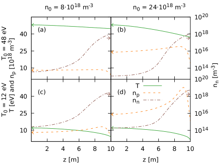
In order to generate different profiles, the upstream electron temperature and upstream electron density were scanned, which allowed for different SOL regimes to be investigated. Fig. 1 shows temperature and density of the electrons, as well as neutral density. The 12 eV temperature simulations are in the high recycling regime, as the temperature drops significantly along the field line. The high temperature simulations are in the low recycling regime (also known as the sheath-limited regime) [23]. Note that these simulations do not feature detachment, which requires a more precise treatment of neutrals.
In order to reduce the interaction of the filaments with neutrals, a second set of background profiles was generated, where the plasma neutrals interaction was limited to ionization. This allows us to keep the recycling dominated fuelling of the plasma, without the need to change the model, except setting . Fig. 2 shows that in this case, the temperature decreases faster towards the target. This leads to slower ion and electron velocities at the target.
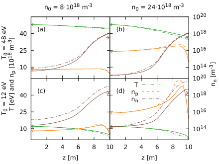
Further, the densities of both plasma and neutrals is increased. The strongest differences between the models is in the low temperature cases.
4 Filament evolution
The filament is seeded as a density and temperature perturbation on top of the background profiles. The initial shape in the perpendicular direction is Gaussian. The width is, unless otherwise noted, 20 mm. In the parallel direction a shape is used with a typical parallel length of 5 m.
Theoretical predictions suggest a scaling of the radial velocity of the filament, that scales with
| (11) | ||||
| for the sheath limited regime and | ||||
| (12) | ||||
for the inertial limited regime [10]. is the perturbation above the background value , for . The pressure perturbation consists of density and temperature perturbation . To simplify the scalings, we take a density perturbation equal to the upstream density, , such that . Doing the same for the temperature perturbation, setting yields for the pressure perturbation . The scalings (11) and (12) reduce to:
| (13) | ||||
| (14) |
yielding a temperature dependence of for the inertial regime and for the sheath limited regime and no dependence on the density. This convention for the filament perturbations will be adopted through out this paper. Within the scaling describes a “background” temperature. As the background temperature changes along the magnetic field lines, it is not obvious how this for the scaling should be calculated.
From the filament simulations the centre of mass was calculated in the radial direction :
| (15) | ||||
| with | ||||
| (16) | ||||
where the cut of density was computed by taking the background density of that cross-section. As the initial amplitude near the target is very small, the shown results are measured near the mid-plane. However the filaments move rigidly, so this velocity is representative of the whole filament.
For each filament simulation, the maximum of the centre-of-mass velocity is computed and compared.
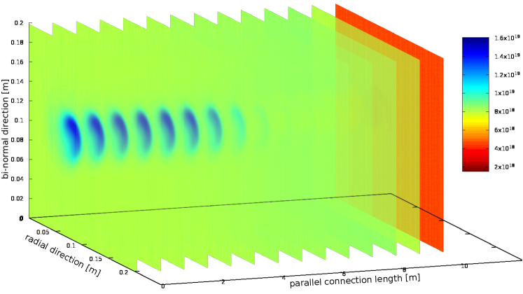
An example of a filament shape is shown in fig. 3. The mushrooming behaviour, typical for these filaments [1, 8, 10], can be seen. The filament is not symmetric in the -direction. This motion in the -direction, due to the temperature perturbation, has been observed and discussed [10, 24]. The temperature perturbation causes an even parity contribution in the potential due to the sheath potential, which causes Boltzmann spinning.
5 Influence on filament velocity
In order to distinguish the direct and the indirect influence of neutrals on filaments, first different neutral models are compared. This will be followed by a study of the background dependence on filaments, before we conclude with results of the filament size dependence.
5.1 Neutrals
In order to study the direct interaction between the neutrals and the filaments, different neutrals-filament interaction models were used.
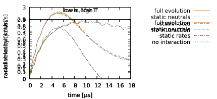
The results are shown in fig. 4. The no interaction case is where the neutral term in the vorticity equation is set to zero. For the other terms the neutrals are kept static and the neutral rates are calculated self consistently. In the static rates case the neutral plasma interaction rates, namely charge exchange rate , ionization rate and recombination rate , are kept at their steady state values. This ensures that areas not affected by the filament are kept at the steady state value. The static rates case represents a state where the neutrals are still interacting with the plasma, but the plasma filament interaction is reduced to the neutral plasma background interaction. The interaction is partially further switched on in the case of the static neutrals. There the neutral profiles are not evolved, but the neutral plasma interaction rates are calculated taking the filament into account. In the full evolution case the interaction is fully enabled. The neutrals are evolved self consistently, and the interaction rates are computed including both background and filament contributions to density and temperature.
These simulations were done for the different backgrounds shown in fig. 1. The result shown in fig. 4 is the one with the strongest difference between the velocities, the background profile with high density and high temperature . It can be seen that there is only a small difference for the static neutrals and static rates cases. In the case where the neutrals are evolved, the filament moves slightly faster. The filament is fastest when the neutrals drag term in the vorticity equation is switched off. In the case where the neutrals are co-evolved with the filament, the filament ‘burn‘ partially through the neutrals which explains why the velocities lie between the static cases and the no interaction case.
This shows that neutrals impact the motion of filament - at least in the high density and high temperature cases. The following results are obtained using the static neutral approximation, as this significantly accelerates the computation. The deviation from the full neutrals evolution is less then 1.5 % in the conditions featured here, which do not include detachment.
In addition to the weak dependence on the direct interaction between filament and neutrals, the filament velocity does vary with background conditions. This is shown in fig. 5, where on the left filaments were seeded on the backgrounds with full neutral interactions. Also shown is the effect of removing charge exchange and recombination from the simulations. This impacts filament velocity through the change in the backgrounds, indicating that neutrals are important and interact with the filament indirectly via the plasma background. In the next section, the dependence of the filament velocities on the background conditions is studied in more detail.
5.2 Background dependence
This section presents the dependence of the filaments radial velocity on the background conditions. Fig. 6 (a) shows the time evolution of filaments seeded on the background profiles shown in fig. 1.
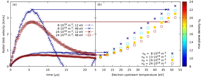
On the right hand side of fig. 6 is a plot of the peak of the filaments radial velocity as a function of the upstream temperature. The velocity increases with an increase of temperature. The velocity decreases with increasing density, with the exception of low temperatures, where this trend is inverted. As the filaments are seeded such that stays constant, the density dependence is not expected from the simple scaling analysis shown in section 4.
Earlier studies in STORM looked at the influence of the resistivity [16]. This was done by artificially changing the resistivity. In this study this is repeated in a self consistent way. In order to change the resistivity, the temperature needs to be changed.
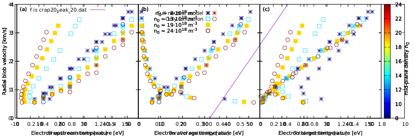
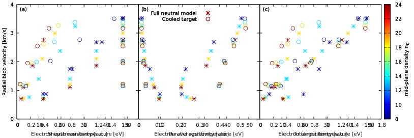
Fig. 7 shows the peak velocity as a function of (a) the sheath resistivity, (b) the plasma resistivity integrated along the magnetic field lines and in (c) the total resistivity, consisting of the sum of both. Note that the non-monotonic behaviour below 1 km/s is because the density at the target reduces quite strongly with decreasing temperature, therefore the sheath resistivity increases, and the colder temperatures have a higher target resistivity. Fig. 7 shows that the resistivity doesn’t have a major impact on the filament dynamics, and the temperature of the filament is more important, for the conditions studied here. As the plasma resistivity is a function of the temperature, the scaling in (b) shows a monotonic decreasing behaviour. This is not an effect of the resistivity, as with increasing resistivity, the vorticity should increase, which would results in faster filaments [16]. This shows that in this self consistent study, the change in resistivity is less important than the associated change in temperature.

The simple scaling analysis shown in section 4 does require a single background temperature, however the temperature is not constant along the magnetic field lines. Fig. 8 shows the filament peak velocities for the different profiles as a function of the upstream temperature, the average temperature and the target temperature. In all cases a monotonic increase with temperature is observed. In the case of the target temperature, the different upstream density profiles collapse approximately onto a single line. This suggests that the target temperature is a good scaling quantity for the radial velocity of the filaments studied here. In fig. 8 (f) the results from the different neutral models are much closer to each other than in fig 8 (d-e) where they are plotted as function of the upstream temperature and the average temperature.
The vorticity equation, which determines the filament radial velocity, represents a balance between parallel, polarization and viscous currents with the driving diamagnetic currents in the filament. As part of the filaments vorticity is closed via polarization currents, we do not expect such a strong dependence on the target temperature. To study this further, a set of simulations was run, removing the density dependence of the plasma viscosity in eq. (5). has otherwise linear density dependence, so an increased density leads to an increased diffusion of the vorticity, thereby reducing the drive.
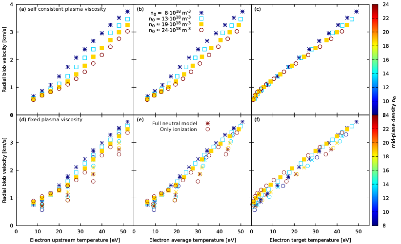
Fig. 9 compares the self consistent viscosity simulation (a-c) with the ones where the plasma viscosity has no density dependence (d-f). The density dependence, if plotted against the upstream temperature, is significantly reduced. In fig. 9 (e) the radial velocity is plotted against the target temperature. Although the points do not collapse onto a single line, they are still reasonably close to a single line. This supports the point that the filaments aren’t only influenced by the target temperature. It is worth noting that a similar data collapse is apparent in fig. 9(d). As there is no reason that filaments should be influenced by the average temperature if the density dependence of the viscosity is fixed, while being influenced by the target temperature in case of the full dynamics, this supports the point that the collapse onto a single line is a coincidence, and most likely will not be true for other conditions. As in the here presented simulations sheath currents play a significant role, the results are not directly applicable to situations where they are suppresed, for example in detached regimes.
Looking at fig. 9 (a) and (d), removing the density dependence of the plasma viscosity reduces the dependence of the filament velocity on the density. For the remaining density dependence, different reasons come into play. The plasma viscosity still has a temperature dependence and for higher densities the target temperature drops to lower values than for higher densities, causing a higher viscosity near the target. This shows that the filaments are indeed influenced by the conditions at the target. Note that the filaments have been seeded unconnected from the sheath, but due to the fast electon motion, they still connect to the target, and are therefore influenced by the plasma conditions at the target.
Another reason for the density dependence is via the neutrals. As shown earlier for the higher density cases the neutrals cause a larger reduction in filament velocity. Further, the background parallel velocity is decreasing with increasing density. The change in the parallel velocity is stronger for lower temperatures. This can be explained by an increasing importance of recycling in comparison to upstream density fuelling. Although this contribution is only small, it might explain to some extent the crossover at low temperatures, where low densities are slower then high densities. This cross over is observed in the case (fig. 9 (b)) and the ionisation only case (fig. 5 (b)), while in the full case the density dependence is reduced.
Finally parallel currents are playing a significant role in the generation of vorticity. The parallel currents are affected by the sheath conditions, as they are flowing through the sheath. Therefore also currents closer to upstream, are influenced by the sheath temperature.
To further test the dependence of the filament velocity on the various temperatures within the system, the upstream and target temperatures have been partially decoupled from one-another. This has been achieved by inserting an artificial heat sink localised near the target to control the target electron temperature independent of the upstream temperature.
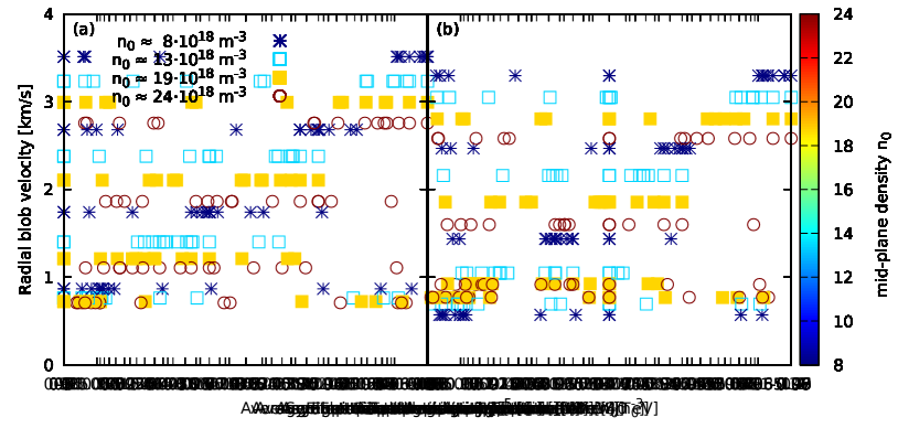
This was done for the simulations with an upstream temperature of eV. The temperature close the target was set to values between 12 eV and 48 eV. The radial velocities are shown in fig. 10. Although the filaments were all seeded with the same perturbation of eV, the filament velocity agrees with the scaling of the target temperature, rather then the upstream temperature. Note that in this case the term is significantly stronger near the target, then in the simulations without the target heat sink. Therefore the vorticity is larger in amplitude near the target, than further upstream. Therefore the viscosity near the target has a strong influence, which results in a strong influence of the target temperature. As the target temperature also influences sheath currents, the strong target temperature dependence of the filament velocity is probably due to both the viscosity as well as the sheath currents.
5.3 Filament size
To study the influence of the size of the filament on its dynamics, different sized filaments have been seeded, and their motion analysed.
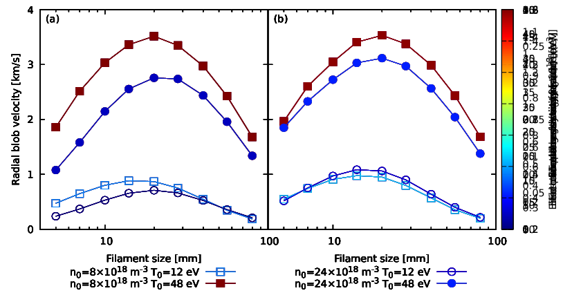
Fig. 11 (a) presents the scan in filament size. It can be seen that the filament size , where the filaments are fastest is for the m-3 between 14 and 20 mm, and for the m-3 between 20 and 28 mm. The position does seem to be only influenced by the upstream density , and not by the temperature.
As already done in the previous section, a scan where the plasma viscosity had no density dependence was performed. This is shown in fig. 11 (b). In this case the fastest filaments are around mm for the 48 eV cases, and between 14 and 20 mm for the 12 eV case. This shows that the density dependence of this point is due to the density dependence of the plasma viscosity, which hasn’t been included in past studies. Further, a weak temperature dependence of is observed. From the simple scaling derived in section 4, a temperature but no density dependence is expected, suggesting that future derivations of should include a self consistent plasma viscosity, and currents due to viscosity.
The stronger density dependence of small filaments can be explained by the density dependence of the viscosity. As for small filaments the currents are closed via currents in the drift plane, where viscous currents can contribute. For large filaments, no dependence on the viscosity is observed, as the currents are closed via the sheath.
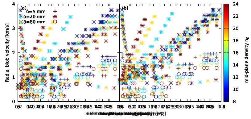
Fig. 12 shows the peak radial velocity for different sized filaments. The ones with size are the fastest ones. The smaller ones and larger ones are significantly slower. The larger ones collapse on a line. This agrees with theory, as the vorticity for larger filaments is mainly closed via sheath currents, therefore a dependence on the sheath conditions is expected. The smaller ones, where the currents are closed mainly via currents in the drift plane, show a stronger dependence on the density. This strong density dependence can be explained by the viscosity. If the density dependence of the viscosity is fixed, they do not collapse that closely onto a single line, suggesting a weaker target dependence compared to larger filaments. As this geometry does not include an X-point, filaments can be connected to the target, and therefore influenced by the target. If a more realistic geometry is used, it is quite likely that at least for the smaller filaments the influenced of the plasma condition at the sheath is reduced.
6 Summary
Filament radial velocities in the scrape-off layer for different background profiles have been studied. Thereby the upstream temperature and density have been varied, resulting in self consistent parallel profiles. The backgrounds do not include gradients in the radial direction. Filaments were seeded on the background profiles, and the radial filament velocity was measured.
It has been shown, that the direct interaction between the filament and the neutrals are most strong in the high density and high temperature case, where a weak reduction of velocity was observed. The indirect interaction, via changing the background profiles have been observed in all cases. To accurately capture filament dynamics, the parallel variation of the background plasma, including interactions with the neutral population, should be included.
Increasing the upstream temperature resulted in faster radial motion of the filament, and decreased with increasing upstream density. This can be explained by the reduced target temperature with increasing density, as the target temperature was shown to be the best ordering parameter for the filaments studied here. As the filament perturbation is seeded unconnected to the sheath, it is the fast electron motion, that connects the filament electricly to the sheath. This way the target temperature dependence can be explained by the temperature dependence of the plasma viscosity and by sheath currents.
The strong target temperature dependence is not only observed for filament sizes close to the critical size but also for larger ones. Here a significant amount of the current is closed via sheath currents. Smaller filaments show a strong dependence on plasma density, due to the density dependence of the plasma viscosity. If this influence is reduced, they show also a strong dependence on the sheath temperature. Further a shift of with density is observed. This is not expected from scaling laws, but can be explained by the density dependence of the plasma viscosity. This suggests that the plasma viscosity should be included if scalings for are derived.
The geometry used does not include an X-point or magnetic shear. Furthermore detachment was not studied here, as a more accurate neutral model would be required. Both these aspects could reduce the target dependence, and further studies are required to validate this findings in the case of detached conditions or in scenarios including high magnetic shear.
7 Acknowledgement
This work has been carried out within the framework of the EUROfusion Consortium and has received funding from the Euratom research and training programme 2014-2018 under grant agreement No 633053 and from the RCUK Energy Programme [grant number EP/P012450/1]. To obtain further information on the data and models underlying this paper please contact PublicationsManager@ukaea.uk. The views and opinions expressed herein do not necessarily reflect those of the European Commission. Simulations in this paper made use of the ARCHER UK National Supercomputing service (www.archer.ac.uk) under the Plasma HEC Consortium EPSRC grant number EP/L000237/1.
References
- [1] D. D’Ippolito, J. Myra, and S. Zweben, “Convective transport by intermittent blob-filaments: Comparison of theory and experiment,” Physics of Plasmas (1994-present), vol. 18, no. 6, p. 060501, 2011.
- [2] J. Roth, E. Tsitrone, A. Loarte, T. Loarer, G. Counsell, R. Neu, V. Philipps, S. Brezinsek, M. Lehnen, P. Coad, C. Grisolia, K. Schmid, K. Krieger, A. Kallenbach, B. Lipschultz, R. Doerner, R. Causey, V. Alimov, W. Shu, O. Ogorodnikova, A. Kirschner, G. Federici, and A. Kukushkin, “Recent analysis of key plasma wall interactions issues for ITER,” Journal of Nuclear Materials, vol. 390–391, pp. 1 – 9, 2009.
- [3] J. A. Boedo, D. Rudakov, R. Moyer, S. Krasheninnikov, D. Whyte, G. McKee, G. Tynan, M. Schaffer, P. Stangeby, P. West, S. Allen, T. Evans, R. Fonck, E. Hollmann, A. Leonard, A. Mahdavi, G. Porter, M. Tillack, and G. Antar Physics of Plasmas, vol. 8, no. 11, pp. 4826–4833, 2001.
- [4] F. Militello and J. T. Omotani, “On the relation between non-exponential scrape off layer profiles and the dynamics of filaments,” Plasma Physics and Controlled Fusion, vol. 58, no. 12, p. 125004, 2016.
- [5] G. Q. Yu and S. I. Krasheninnikov, “Dynamics of blobs in scrape-off-layer/shadow regions of tokamaks and linear devices,” Physics of Plasmas, vol. 10, no. 11, pp. 4413–4418, 2003.
- [6] G. Yu, S. Krasheninnikov, and P. Guzdar, “Two-dimensional modelling of blob dynamics in tokamak edge plasmas,” Physics of Plasmas (1994-present), vol. 13, no. 4, p. 042508, 2006.
- [7] O. Garcia, N. Bian, and W. Fundamenski, “Radial interchange motions of plasma filaments,” Physics of Plasmas (1994-present), vol. 13, no. 8, p. 082309, 2006.
- [8] L. Easy, F. Militello, J. Omotani, B. Dudson, E. Havlíčková, P. Tamain, V. Naulin, and A. H. Nielsen, “Three dimensional simulations of plasma filaments in the scrape off layer: A comparison with models of reduced dimensionality,” Physics of Plasmas, vol. 21, no. 12, 2014.
- [9] J. R. Angus, M. V. Umansky, and S. I. Krasheninnikov, “Effect of drift waves on plasma blob dynamics,” Phys. Rev. Lett., vol. 108, p. 215002, May 2012.
- [10] N. R. Walkden, L. Easy, F. Militello, and J. T. Omotani, “Dynamics of 3d isolated thermal filaments,” Plasma Physics and Controlled Fusion, vol. 58, no. 11, p. 115010, 2016.
- [11] J. Leddy, H. V. Willett, and B. D. Dudson, “Simulation of the interaction between plasma turbulence and neutrals in linear devices,” Nuclear Materials and Energy, October 2016. This is an author-produced version of the published paper. Uploaded in accordance with the publisher?s self-archiving policy. Further copying may not be permitted; contact the publisher for details. (no embargo).
- [12] N. Bisai and P. Kaw, “Role of neutral gas in scrape-off layer of tokamak plasma in the presence of finite electron temperature and its gradient,” Physics of Plasmas (1994-present), vol. 23, no. 9, p. 092509, 2016.
- [13] C. Wersal and P. Ricci, “A first-principles self-consistent model of plasma turbulence and kinetic neutral dynamics in the tokamak scrape-off layer,” Nuclear Fusion, vol. 55, no. 12, p. 123014, 2015.
- [14] A. S. Thrysøe, L. E. H. Tophøj, V. Naulin, J. J. Rasmussen, J. Madsen, and A. H. Nielsen, “The influence of blobs on neutral particles in the scrape-off layer,” Plasma Physics and Controlled Fusion, vol. 58, no. 4, p. 044010, 2016.
- [15] D. Schwörer, N. Walkden, H. Leggate, B. Dudson, F. Militello, T. Downes, and M. Turner, “Influence of plasma background including neutrals on scrape-off layer filaments using 3d simulations,” Nuclear Materials and Energy, vol. 12, pp. 825 – 830, 2017.
- [16] L. Easy, F. Militello, J. Omotani, N. Walkden, and B. Dudson, “Investigation of the effect of resistivity on scrape off layer filaments using three-dimensional simulations,” Physics of Plasmas (1994-present), vol. 23, no. 1, p. 012512, 2016.
- [17] B. Dudson, M. Umansky, X. Xu, P. Snyder, and H. Wilson, “BOUT++: A framework for parallel plasma fluid simulations,” Computer Physics Communications, vol. 180, no. 9, pp. 1467 – 1480, 2009.
- [18] B. D. Dudson, A. Allen, G. Breyiannis, E. Brugger, J. Buchanan, L. Easy, S. Farley, I. Joseph, M. Kim, A. D. McGann, J. T. Omotani, M. V. Umansky, N. R. Walkden, T. Xia, and X. Q. Xu, “BOUT++: Recent and current developments,” Journal of Plasma Physics, vol. 81, 1 2015.
- [19] A. N. Simakov and P. J. Catto, “Drift-ordered fluid equations for field-aligned modes in low- collisional plasma with equilibrium pressure pedestals,” Physics of Plasmas, vol. 10, no. 12, pp. 4744–4757, 2003.
- [20] A. N. Simakov and P. J. Catto, “Erratum: “drift-ordered fluid equations for field-aligned modes in low- collisional plasma with equilibrium pressure pedestals” [phys. plasmas 10, 4744 (2003)],” Physics of Plasmas, vol. 11, no. 5, pp. 2326–2326, 2004.
- [21] R. Chodura, “Plasma-wall transition in an oblique magnetic field,” 1981.
- [22] P. C. Stangeby, “The bohm–chodura plasma sheath criterion,” Physics of Plasmas, vol. 2, no. 3, pp. 702–706, 1995.
- [23] P. C. Stangeby et al., The plasma boundary of magnetic fusion devices, vol. 224. Institute of Physics Publishing Bristol, 2000.
- [24] J. Myra, D. D’ippolito, S. Krasheninnikov, and G. Yu, “Convective transport in the scrape-off-layer by nonthermalized spinning blobs,” Physics of Plasmas (1994-present), vol. 11, no. 9, pp. 4267–4274, 2004.