Send correspondence to VSD – email: vik.dhillon@sheffield.ac.uk, tel: +44 114 222 4528
First light with HiPERCAM on the GTC
Abstract
HiPERCAM is a quintuple-beam imager that saw first light on the 4.2 m William Herschel Telescope (WHT) in October 2017 and on the 10.4 m Gran Telescopio Canarias (GTC) in February 2018. The instrument uses re-imaging optics and 4 dichroic beamsplitters to record (300–1000 nm) images simultaneously on its five CCD cameras. The detectors in HiPERCAM are frame-transfer devices cooled thermo-electrically to C, thereby allowing both long-exposure, deep imaging of faint targets, as well as high-speed (over 1000 windowed frames per second) imaging of rapidly varying targets. In this paper, we report on the as-built design of HiPERCAM, its first-light performance on the GTC, and some of the planned future enhancements.
keywords:
instrumentation: detectors – instrumentation: photometers – techniques: photometric1 INTRODUCTION
The study of astrophysical objects that vary in brightness is set to be revolutionised in the coming years with the advent of major new survey facilities like Gaia, SKA, LSST and Euclid. The plethora of interesting new targets that these facilities are expected to reveal will require detailed follow-up on large-aperture telescopes. HiPERCAM has been designed to perform this follow-up role, providing CCD imaging in five optical bands () simultaneously at frame rates ranging from 0.001 Hz to 1000 Hz. The scientific motivation and preliminary design of HiPERCAM have been described before[1], and details of the HiPERCAM data acquisition system are described elsewhere at this conference[2]. In this paper, we report on the final design and first-light performance of the instrument when mounted on the GTC on La Palma. We also describe some of the instrument enhancements we are planning to implement in the near future.
2 FINAL DESIGN
The HiPERCAM project began in January 2014, the start date of the €3.5M European Research Council Advanced Grant that funded the instrument. First light took place just under 4 years after this date, on budget and on time.
The design of HiPERCAM is based on our successful predecessor instrument, ULTRACAM[3], but offers a very significant advance in performance, as shown in Table 1 and described in the following sections.
| ULTRACAM | HiPERCAM | Notes | |
|---|---|---|---|
| Number of simultaneous bands | 3 () | 5 () | |
| Readout noise | 3 e- at 100 kHz | 4.5 e- at 263 kHz | Dummy output (HiPERCAM) |
| CCD operating temperature | 233 K | 183 K | |
| Dark current | 360 e-/pix/hr | 100 e-/pix/hr | |
| Longest exposure time | 30 s | 1800 s | |
| Highest frame rate | 400 Hz | 1050 Hz | 2424 pixel windows, bin 66 |
| Field of view on WHT | 5.1’5.1’ | 10.2’x5.1’ | platescale 0.3”/pixel |
| Field of view on GTC | – | 2.8’1.4’ | 0.081”/pixel (HiPERCAM) |
| Probability of comparison | 45% | 78% | WHT, galactic latitude = 30∘ |
| Comparison star pick-off | No | Yes | Under development – Sect. 2.6 |
| Dummy CCD outputs | No | Yes | |
| Deep depletion | No | Yes | |
| QE at 700/800/900/1000 nm | 83/61/29/5 % | 88/78/53/13 % | |
| Fringe suppression CCDs | No | Yes | |
| Fringe amplitude in | 10% | 1% |
2.1 Optics
A ray trace through the HiPERCAM optics has been presented before[1]. Light from the telescope is first collimated and then split into five beams using four dichroic beamsplitters. The beam in each arm then passes through a re-imaging camera, which focuses the light through a bandpass filter and cryostat window onto a CCD. The HiPERCAM collimator has been designed for use on both the 4.2 m William Herschel Telescope (WHT) on La Palma and the 3.5 m New Technology Telescope (NTT) on La Silla, giving a platescale of 0.3”/pixel and 0.35”/pixel, and a field of view of 11.4’ and 13.4’, respectively, along the diagonal of the detector. The same collimator also gives excellent optical performance on the 10.4 m Gran Telescopio Canarias (GTC) on La Palma, giving a platescale of 0.081”/pixel and a field of view of 3.1’ (diagonal).
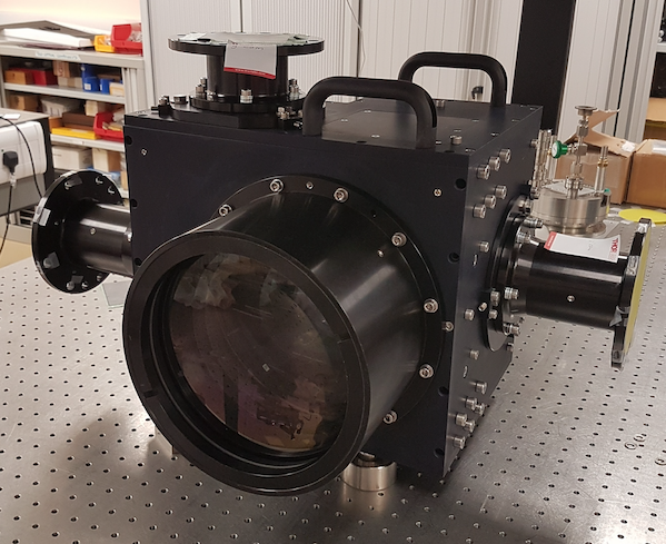
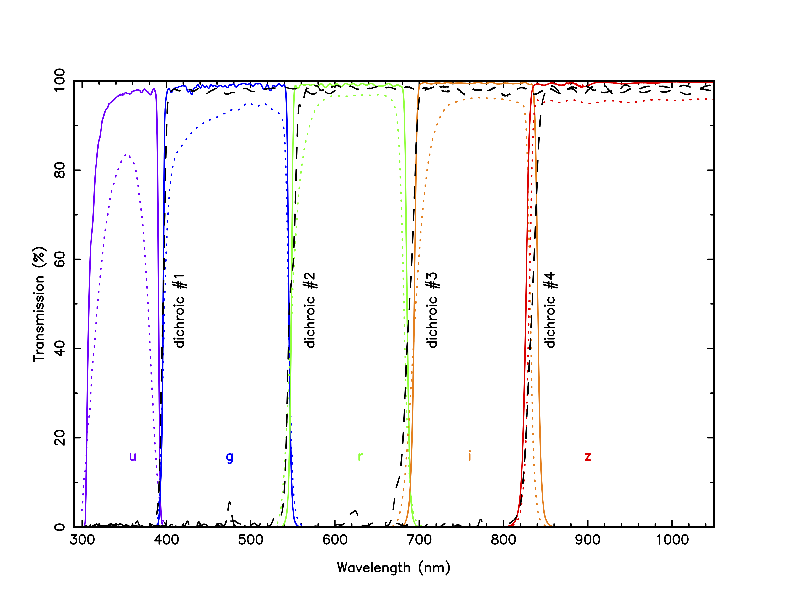
The dichroics, lens barrels, filters and CCDs are housed in/on an aluminium hull, which forms a sealed system to light and dust – see Fig. 1. The bandpasses of the five arms are defined by a set of so-called “Super” SDSS filters (Fig. 2), which were designed specifically for HiPERCAM. These filters do not use coloured glasses, but instead rely only on multi-layer coatings to define the filter bandpasses, with the cut-on/off wavelengths designed to match the original SDSS filter set[4]. The percentage improvements in throughput of the HiPERCAM Super SDSS filters, which we call , over the original SDSS filters, , are 41/9/6/9/5 %, respectively.
 |
 |
2.2 Detectors
The HiPERCAM CCDs have been described in detail elsewhere[1, 2]. The specifications of the five detectors currently in use in HiPERCAM are detailed in Table 2.
| CCD model | Teledyne e2v CCD231-42 |
|---|---|
| Cosmetic grade | 1 |
| Architecture | Split frame transfer, back thinned, 2-phase, NIMO |
| Format | 20482048 pixels |
| Image area | 20481024 pixels |
| Storage area | 2 2048512 pixels |
| Pixel size | 15 m |
| Outputs | 4 |
| Readout noise | 3.2 e- at 200 kHz, single-ended |
| Gain | 1.2 e-/ADU |
| Dark current | 10 e-/pix/hr at 173 K |
| Deep depletion Si | and bands |
| AR coatings | Astro Broadband in , Astro Multi-2 in |
| Peak QE in bands | 76/89/88/88/78 % |
| Fringe suppression | and bands |
| Fringe amplitude | % in and % in band |
| Full well | 120 ke- |
| Non linearity | 0.5% |
| Vertical clocking | 10 s/row |
| Horizontal clocking | 0.1 s/pix, split serial-register |
| Full frame time (bin 11) | 3.0 s in slow, 1.25 s in fast readout mode |
| Full frame time (bin 22) | 0.9 s in slow, 0.4 s in fast readout mode |
| Drift-mode frame time | 0.0009 s with 2424 pixel windows, bin 66 |
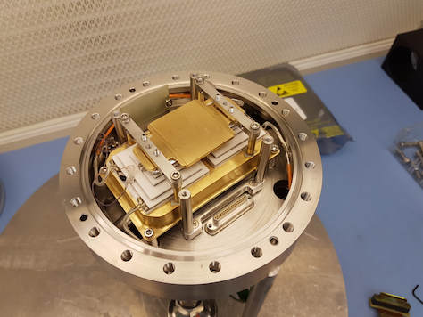
The HiPERCAM detectors need to be cooled to below 187 K in order to achieve the dark current requirement of e-/pixel/hr, which corresponds to 10% of the faintest sky level we can observe with HiPERCAM (set by observations in the -band in dark time on the GTC). Cooling to below 187 K therefore ensures that dark current is always a negligible noise source in HiPERCAM. We looked at a number of cooling options[1] before deciding to use thermo-electric (peltier) coolers (TECs), which are the simplest, cheapest, lightest and most compact of coolers. Our solution uses two Marlow NL5010 five-stage TECs mounted side by side, as shown in Fig. 3. Our detector head design uses all-metal seals rather than o-rings in order to minimize leaks. We went to great lengths to avoid using any materials inside the detector heads that could outgas. So, for example, we mounted the pre-amplifier board outside the head[2], and used a corrugated indium foil to make good thermal connections between the heatsink, TECs and cold plate. We also reduced outgassing by thoroughly cleaning all components prior to assembly, and then baking the assembled head whilst vacuum pumping. Even with all of these precautions, outgassing limits the vacuum hold time of the HiPERCAM CCD heads to around 1 week, due primarily to the small interior volume of the heads ( litres) and the lack of a sufficiently cold, large-area interior surface to give effective cryopumping. Fortunately, it only takes a few minutes to pump down the heads whilst on the telescope, thanks to the use of a 5-way vacuum manifold system permanently installed on the instrument.
|
The heat generated by the TECs is extracted using a 278 K water-glycol cooling circuit. To ensure that cooling fluid of the same temperature enters each of the 5 CCD heads, the heads are connected in parallel rather than series, via two 6-way manifolds (the sixth arm is for cooling the NGC controller). Each arm in this parallel circuit is equipped with a flow sensor connected to a Honeywell Minitrend GR Data Recorder mounted in the electronics cabinet. As well as providing a display of the flow rate through each CCD head, the data recorder has relays that can switch off the power to the TEC power supplies if the flow rate in any head drops below a user-defined limit, thereby protecting the CCDs from overheating. As a backup to this system, the TEC power supplies themselves (made by Meerstetter, model LTR-1200) have a high-temperature cut-off facility: if the temperature of the heat-sink in the CCD head rises above a user-defined value, such as would occur if the coolant supply fails, the power to the TEC is automatically shut off. The TEC power supplies are able to maintain the CCD temperatures at their C set points to within C.
In case of high humidity, HiPERCAM has a 5-way manifold that enables clean, dry air from a telescope supply to be blown across each of the CCD windows at approximately 1 litre/min to prevent condensation.
2.3 Mechanics
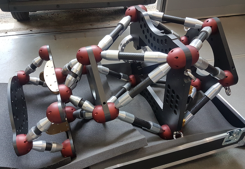 |
The HiPERCAM opto-mechanical chassis is a triple octopod composed of 3 large aluminium plates connected by carbon fibre struts, as shown in Fig. 4. This design ensures a stiff, compact (1.25 m long), light-weight (220 kg) and open structure, which is relatively insensitive to temperature variations. These characteristics make HiPERCAM easy to maintain, transport and mount/dismount at the telescope.
The top plate of the triple octopod is used to mount the instrument onto the telescope, the middle plate is used to mount the hull on (Fig. 1), and the bottom plate is used to mount the CCD controller onto the instrument. Two different interface collars are used to attach HiPERCAM onto the rotator of the WHT and GTC, and place the instrument at the correct distance from the respective telescope focal planes (see Fig. 5).
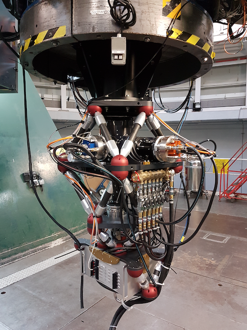 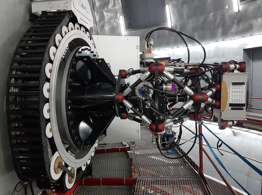
|
2.4 Data acquisition system
The HiPERCAM data acquisition system (DAS) has been described in detail elsewhere[1, 2]. The DAS in HiPERCAM is detector limited, i.e. the throughput of data from the output of the CCDs to the hard disk on which it is archived is always greater than the rate at which the data comes off the CCDs. This means that the instrument is capable of running continuously all night at its maximum data rate without ever having to pause for archiving of data. All CCDs are read out simultaneously and have identical exposure start and end times. In order to change the exposure times of the CCDs with respect to each other, it is possible to skip the readout of selected CCDs using the NSKIP parameter. For example, if NSKIP is set to 3,2,1,2,3 for the CCDs, and the exposure time is set to 10 s, then the CCD controller will read out only the -band CCD on the first readout cycle (giving a 10 s exposure), then the , and -band CCDs on the second cycle (giving and a 20 s exposure), then the , and -band CCDs on the third cycle (giving and a 30 s exposure), etc.
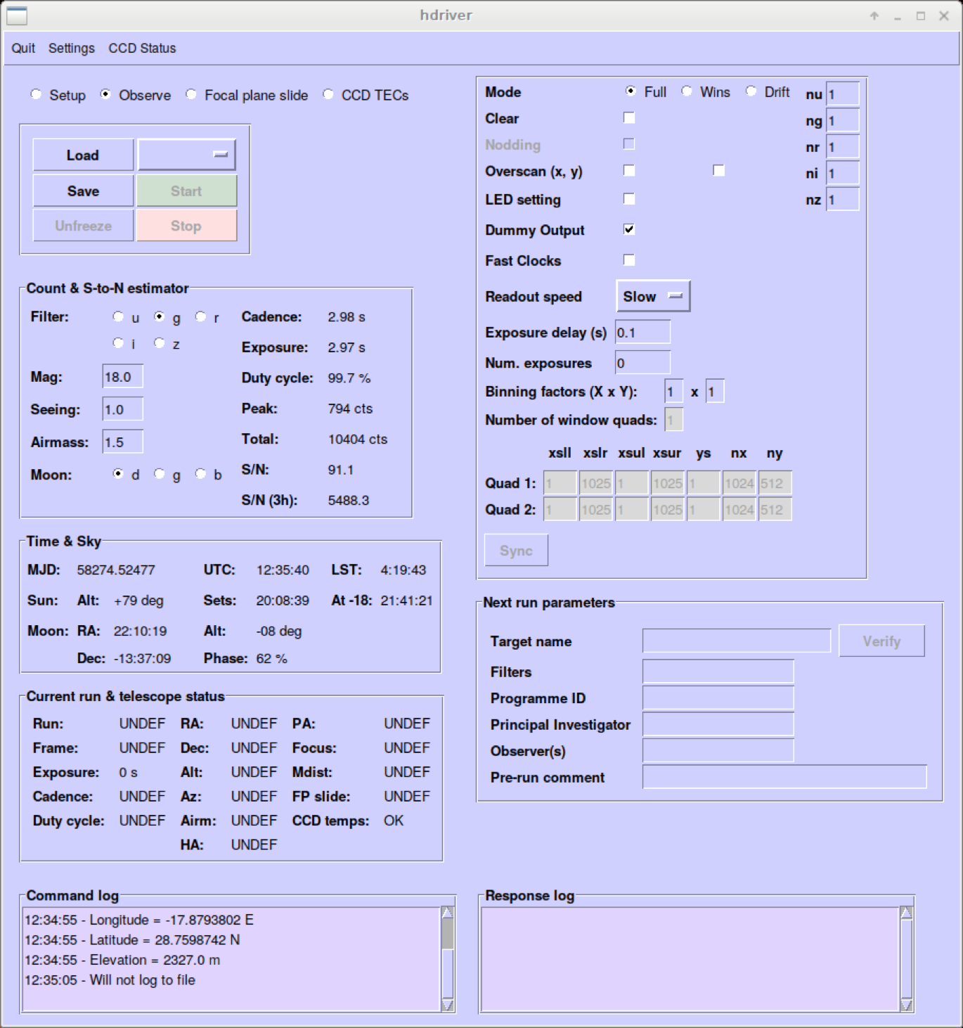 |
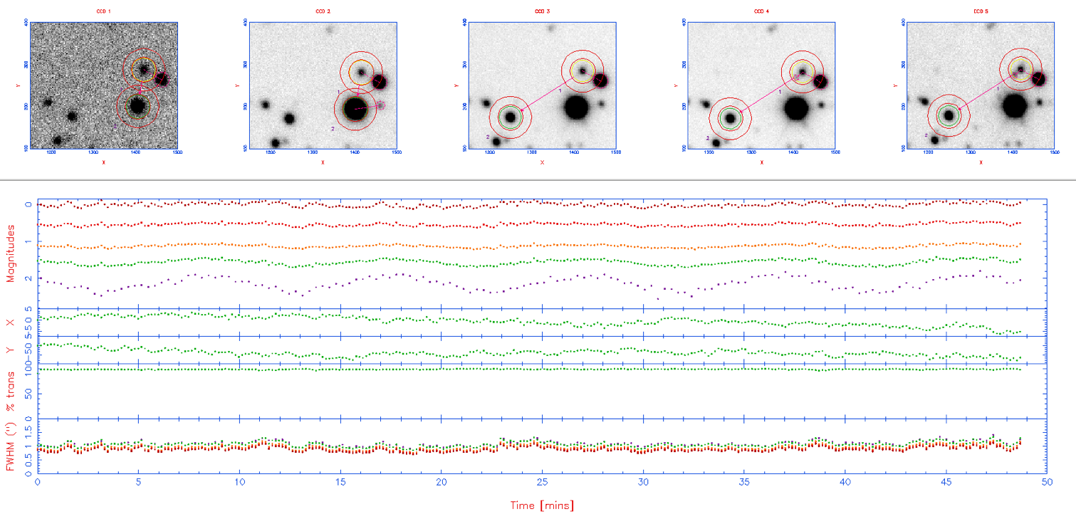
The HiPERCAM graphical user interface (GUI) is shown in Fig. 6. The top right of the GUI shows three buttons that allows the astronomer to change the readout mode: full frame, windowed or drift mode[3]. Below this are the various CCD readout parameters, giving the astronomer complete control over the detector setup. The number of exposures is usually set to zero in the GUI and the green Start button is then pressed: the data acquisition system will then take data continuously until the red Stop button is pressed. All frames of a HiPERCAM run on a target are written to a single, custom-format FITS file. The HiPERCAM data-reduction pipeline software (see Fig. 7) reads this file and provides a quick-look reduction of the data whilst observing. The pipeline is a fully-featured photometry reduction package and so can also be used off-line to produce publication-ready light curves.
 |
2.5 On-sky performance
We commissioned HiPERCAM on the sky for the first time on the WHT during October 2018. This was a short run of only 1 commissioning night and 4 science nights, and was intended primarily to be a shake-down of the instrument prior to commissioning on the GTC. The instrument was then moved to the GTC, where we were allocated 3 commissioning nights and 10 science nights in February 2018. We suffered from terrible weather during this run, and only observed for the last 3 nights, when we completed all of the commissioning. Three more observing runs followed in April, May and June 2018, totalling 16 nights. A wide range of science was performed during this time, including the observation of black holes, white dwarfs, neutron stars, brown dwarfs, extrasolar planets/asteroids, AGN, FRBs, GRBs, SNe and ultra-diffuse galaxies. We report on the performance of HiPERCAM on the GTC below.
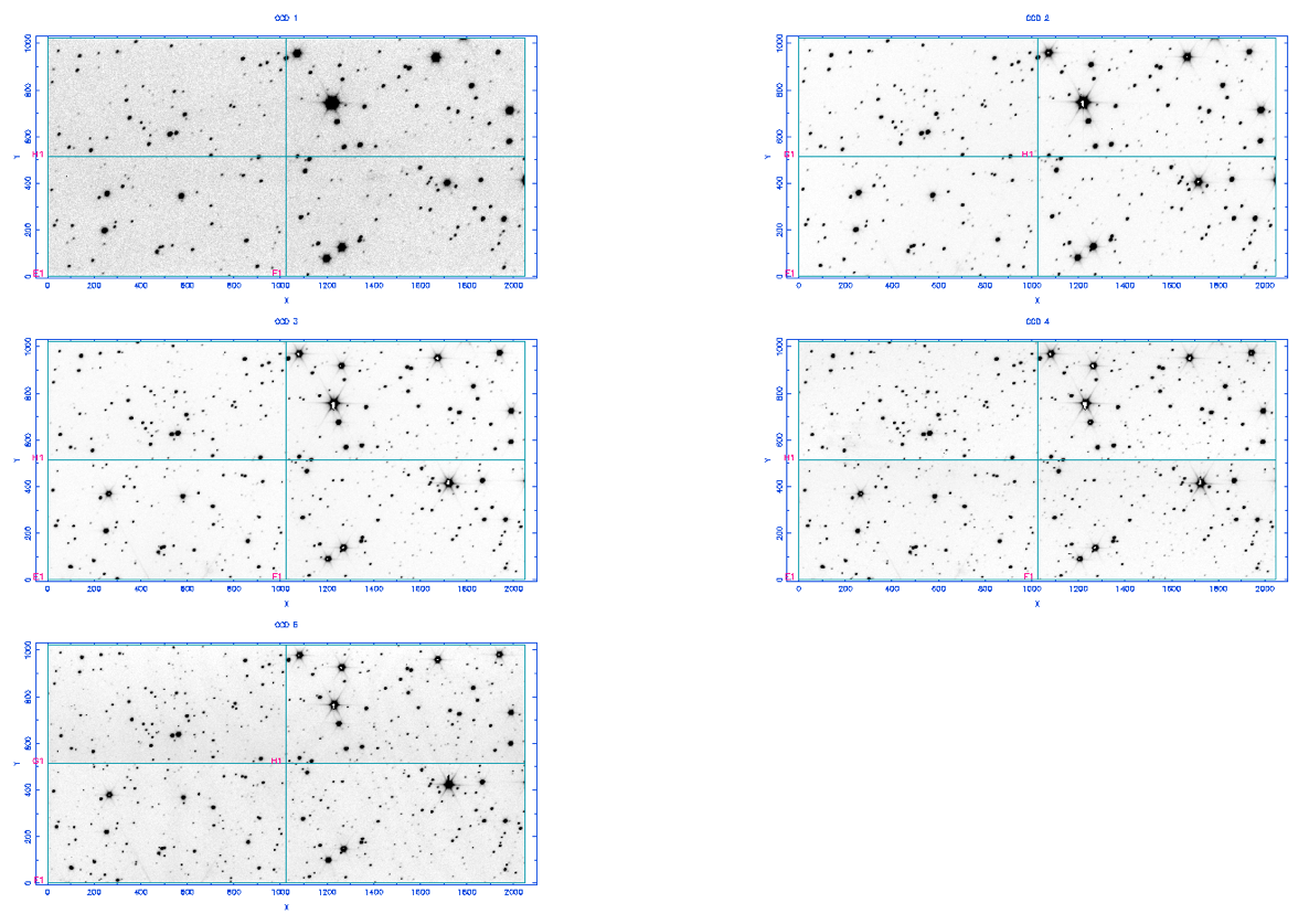
An example star field observed with HiPERCAM on the GTC is shown in Fig. 8. The FWHM of the stars in these images are , , , , , with no discernible variation with field angle. This indicates that HiPERCAM on the GTC can provide seeing-limited images across the whole field of view in even the very best seeing conditions on La Palma. Since the dichroics operate in a collimated beam and have anti-reflection coatings on their rear surfaces, we do not expect to see any ghosting in our images, and this is indeed the case: a careful inspection of the brightest stars in Fig. 8 reveals no discernible ghosting. The pixel positions of the stars at the corners of the field of view are the same on all 5 CCDs, to within approximately 5 pixels (75 m), indicating that there is no discernible variation of platescale with wavelength and that the CCD heads are well aligned with respect to each other. Twilight-sky flat fields show no discernible vignetting in the corners of the field of view.
 |
The measured photometric zero points of HiPERCAM on the GTC, defined here as the magnitude of a star that would give 1 electron per second above the atmosphere, are: , , , , . The numbers in brackets show the corresponding values for OSIRIS, the common-user, single-channel optical imager at the GTC[5]. These two sets of zero points were measured within a few days of each other during May 2018, using observations of SDSS standard stars. It can be seen that unless one needs the full 7.8’ field of view of OSIRIS, or just one of the redder bands, it is much more efficient to use HiPERCAM for standard imaging at the GTC, and one would also gain from the huge reduction in dead time between exposures (0.01 s with HiPERCAM, 21 s with OSIRIS).
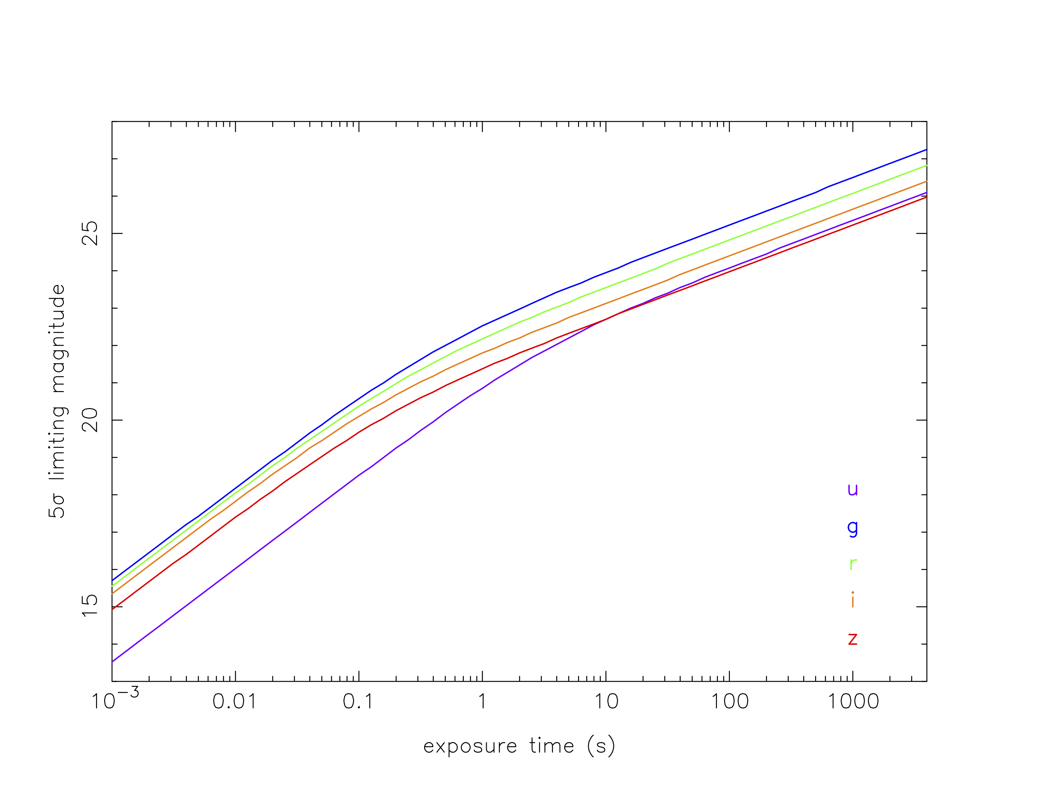
The 5 limiting magnitudes of HiPERCAM on the GTC are shown as a function of exposure time in Fig. 9, calculated using the zero points given above. It can be seen that it is possible to achieve a limiting magnitude of in a single 0.001 s exposure, in 1 s, and in 1800 s.
 |
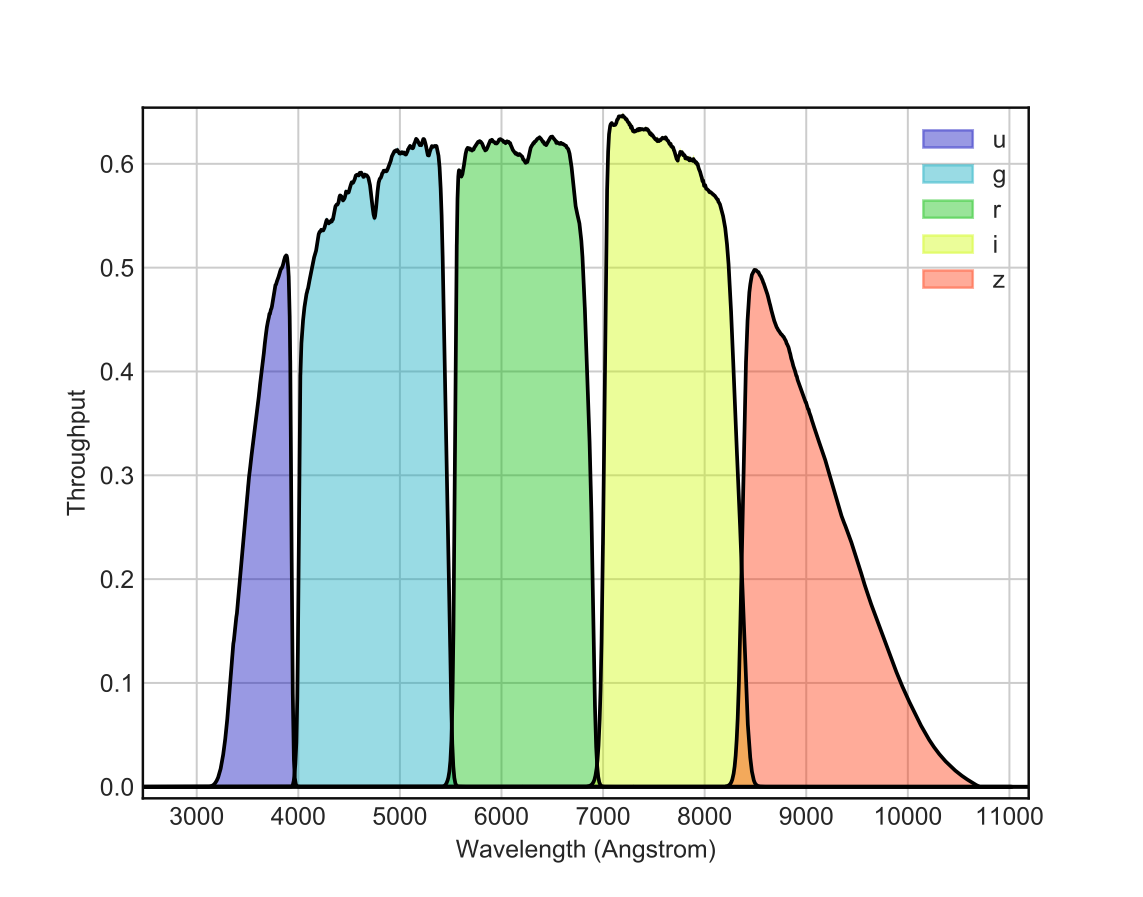
The throughput curves of HiPERCAM, which include all optics and CCDs but not the atmosphere and telescope, are shown in Fig. 10. The throughput peaks at over 60% in , , and 50% in , . This high throughput has been achieved by using high-performance multi-layer coatings on the lenses, dichroics, filters and windows, as well as CCDs optimised for operation in each band.
 |
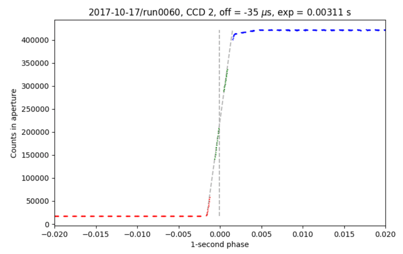
We measured the accuracy of the GPS absolute timestamping of each CCD frame in HiPERCAM by observing an LED connected to the pulse-per-second (PPS) output of our GPS system. An example observation is shown in Fig. 11, where we plot the light curve of the LED phase-folded on its 1 s period. The shape of the light curve is a convolution of two top-hat functions, one for the LED pulse and the other for the exposure time duration (in this example, 0.003 s). Hence the folded light curve exhibits a ramp, the centre of which should correspond to the start of the GPS second. Fig. 11 shows that this is indeed the case: the offset between the start of the GPS second and centre of the ramp is only 35 s and is set by the measurement accuracy of our experiment. Hence we can say that the absolute timestamping of each CCD frame in HiPERCAM is accurate to better than tens of microseconds.
 |
2.6 Future plans
HiPERCAM was removed from the GTC rotator in June 2018 so that an autoguider can be installed. The instrument will be remounted on the telescope from September 2018 to the end of the year for more science runs. In 2019, HiPERCAM will share the Folded Cassegrain focus of the GTC with CanariCam[6]. The situation from 2020 onwards is less clear at the moment, due to the arrival of MIRADAS at the GTC[7].
We are planning on making two enhancements to HiPERCAM during the coming year. The first is to modify the CCD preamp boards so that it is possible to switch the bandwidth from the current value of 1.06 MHz[2] to approximately half this value. In this way, we hope to reduce the readout noise from its current value of e- to e- in slow readout mode (263 kHz).
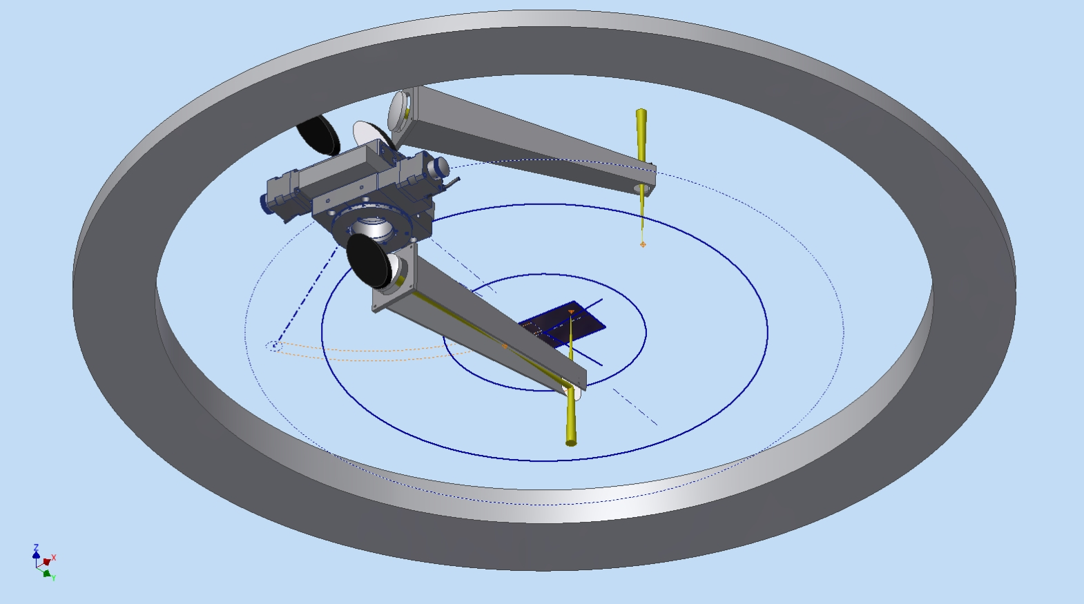
The second enhancement is to implement a COMParison star Pick-Off system (COMPO), as shown in Fig. 12. Light from a bright comparison star that falls outside the 3.1’ diagonal field of view of HiPERCAM, but within the 10’ diameter field of view of the Folded Cassegrain focus of the GTC, is collected by a pick-off arm. The light is then redirected to a second arm, via a set of relay optics, which injects the starlight onto one of the corners of the HiPERCAM CCDs. In this way it is possible to use much brighter comparison stars than would usually be available for differential photometry. This will be of particular importance when observing bright targets, like exoplanet host stars, for which nearby comparison stars of comparable or greater brightness are rare. More quantitatively, without COMPO, there is a 90% probability of finding a comparison star of magnitude in the field of view, whereas with COMPO one will be able to find comparison stars of magnitude with the same probability. COMPO will also be of great benefit to most -band observations, as many of the targets observed by HiPERCAM tend to be blue (e.g. white dwarfs) and hence bright in the -band, whereas most comparison stars tend to be red and hence faint in the -band.
 |
3 CONCLUSIONS
We have described the as-built design and first-light performance of HiPERCAM on the GTC, as well as some of the enhancements we are planning to implement over the coming year. The on-sky results demonstrate that HiPERCAM is performing to specification. The instrument is now entering its exploitation phase on the GTC, and promises to revolutionise the field of high time-resolution optical astrophysics.
Acknowledgements.
HiPERCAM is funded by the European Research Council under the European Union’s Seventh Framework Programme (FP/2007-2013) under ERC-2013-ADG Grant Agreement no. 340040 (HiPERCAM). We would like to thank the staff of the mechanical workshops at the University of Sheffield and the UKATC for their major contribution to the project. We would also like to thank the staff of the ING and GTC for their assistance during commissioning.References
- [1] Dhillon, V. S., Marsh, T. R., Bezawada, N., Black, M., Dixon, S., Gamble, T., Henry, D., Kerry, P., Littlefair, S., Lunney, D. W., Morris, T., Osborn, J., and Wilson, R. W., “HiPERCAM: a high-speed quintuple-beam CCD camera for the study of rapid variability in the universe,” in [Ground-based and Airborne Instrumentation for Astronomy VI ], Proc. SPIE 9908, 99080Y (Aug. 2016).
- [2] Bezawada, N., Gao, X., Henry, D., Black, M., Miller, C., Lunney, D., Dhillon, V., Littlefair, S., Kerry, P., Gamble, T., Dixon, S., Parsons, S., Marsh, T., Mehrgan, L., Stegmeier, J., and Ives, D., “Configuration of readout electronics and data acquisition for the HiPERCAM instrument,” in [High Energy, Optical, and Infrared Detectors for Astronomy VIII ], Proc. SPIE 10709 (2018).
- [3] Dhillon, V. S., Marsh, T. R., Stevenson, M. J., Atkinson, D. C., Kerry, P., Peacocke, P. T., Vick, A. J. A., Beard, S. M., Ives, D. J., Lunney, D. W., McLay, S. A., Tierney, C. J., Kelly, J., Littlefair, S. P., Nicholson, R., Pashley, R., Harlaftis, E. T., and O’Brien, K., “ULTRACAM: an ultrafast, triple-beam CCD camera for high-speed astrophysics,” MNRAS 378, 825–840 (July 2007).
- [4] Fukugita, M., Ichikawa, T., Gunn, J. E., Doi, M., Shimasaku, K., and Schneider, D. P., “The Sloan Digital Sky Survey Photometric System,” AJ 111, 1748 (Apr. 1996).
- [5] Cepa, J., Aguiar-Gonzalez, M., Bland-Hawthorn, J., Castaneda, H., Cobos, F. J., Correa, S., Espejo, C., Fragoso-Lopez, A. B., Fuentes, F. J., Gigante, J. V., Gonzalez, J. J., Gonzalez-Escalera, V., Gonzalez-Serrano, J. I., Joven-Alvarez, E., Lopez-Ruiz, J.-C., Militello, C., Cano, L. P., Perez, A., Perez, J., Rasilla, J. L., Sanchez, B., and Tejada, C., “OSIRIS tunable imager and spectrograph for the GTC. Instrument status,” in [Instrument Design and Performance for Optical/Infrared Ground-based Telescopes ], Iye, M. and Moorwood, A. F. M., eds., Proc. SPIE 4841, 1739–1749 (Mar. 2003).
- [6] Telesco, C. M., Packham, C., Ftaclas, C., Hough, J. H., Moerchen, M. M., Hanna, K. T., Julian, J. A., Varosi, F., Julian, R. E., Bennett, G., Murphey, C., Reyes, F., and Warner, C., “Day-one science with CanariCam, the Gran Telescopio Canarias multi-mode mid-infrared camera,” in [Ground-based and Airborne Instrumentation for Astronomy II ], Proc. SPIE 7014, 70140R (July 2008).
- [7] Eikenberry, S. S., Raines, S. N., Stelter, R. D., Garner, A., Dallilar, Y., Ackley, K., Bennett, J. G., Murphey, C. H., Miller, P., Tooke, D., Williams, L., Chinn, B., Mullin, S. A., Schofield, S. L., Warner, C. D., Varosi, F., Zhao, B., Eikenberry, S. A., Vega, C., Donoso, H. V., Sabater, J., Gómez, J. M., Torra, J., Rosich Minguell, J., Garzón López, F., Cardiel, N., Gallego Maestro, J., Marín-Franch, A., Galipienzo, J., Carrera Astigarraga, M. Á., Fitzgerald, G. J., Prees, I., Stolberg, T. M., Kornik, P. A., Ramaprakash, A. N., Burse, M. P., Punnadi, S. P., and Hammersley, P., “MIRADAS for the Gran Telescopio Canarias,” in [Ground-based and Airborne Instrumentation for Astronomy VI ], Proc. SPIE 9908, 99081L (Aug. 2016).