Experimental realization of a quantum CNOT gate for orbital angular momentum and polarization with linear optical elements
Abstract
We propose and experimentally demonstrate that a Mach-Zehnder interferometer composed of polarized beam splitters and a pentaprism in the place of one of the mirrors works as a linear optical quantum controlled-NOT (CNOT) gate. To perform the information processing, the polarization and orbital angular momentum (OAM) of the photons act as the control and target qubits, respectively. The readout process is simple, requiring only a linear polarizer and a triangular diffractive aperture before detection. The viability and stability of the experiment makes the present proposal a valuable candidate for future implementations in optical quantum computation protocols.
I Introduction
The capacity of a photon to carry information can be greatly increased if one accesses its many degrees of freedom: spatial, polarization, frequency and the orbital angular momentum (OAM). In doing so, it is possible to make a single-photon encode multiple qubits, whose manipulation can give rise to the implementation of photonic quantum logic gates, which are the building blocks of future technologies such as quantum communication Nielsen and Chuang (2011); Ekert (1991); Bennett and Wiesner (1992); Bennett et al. (1993) and quantum computation Knill et al. (2001); Bouwmeester et al. (2010); Shor (1997); Lanyon et al. (2007). The great advantage in using light for such purposes is the fact that photons are practically unaffected by detrimental decohering processes Zurek (2003); Schlosshauer (2005); de Lima Bernardo (2017); Balthazar et al. (2016, 2014, 2015). A celebrated result in quantum information science was the demonstration that single-qubit and controlled-NOT (CNOT) gates together are sufficient for realizing universal quantum computation DiVincenzo (1995). In realizing such task with optical schemes, the information is commonly encoded on the polarization degree of freedom, in which the one-qubit logic gates are carried out with birefringent waveplates Kok and Lovett (2010). However, the implementation of an optical two-qubit CNOT operation for a single-photon demands necessarily the control of a second degree of freedom Kok et al. (2007).
In 2001, Knill, Laflamme and Milburn Knill et al. (2001) demonstrated a probabilistic method to realize efficient quantum computation, which is efficient and scalable, using only linear optical elements, photodetectors and single-photon sources. After that, a number of works have proposed ways to construct CNOT gates with linear optics. For example, Fiorentino et al. created a linear CNOT logic gate using the polarization and momentum of a single photon Fiorentino and Wong (2004). Oliveira et. al. realized a single-photon CNOT gate manipulating the polarization and the transverse spatial modes of the electromagnetic field de Oliveira et al. (2005). Deng et. al. theoretically proposed a CNOT operation involving the polarization and the OAM of a single-photon, but the use of computer generated hologram (CGH) inside the circuit was required Deng et al. (2007). More recently, an experimental realization of a photonic CNOT gate also involving polarization and OAM was reported, however, making use of nonlinear optical elements Zeng et al. (2016).
In this work, we theoretically study and experimentally verify an optical implementation of a CNOT logic gate manipulating the polarization and OAM degrees of freedom only with linear optical elements. The polarization orientation and the sign of the OAM state are the control and target qubits, respectively. Contrary to the theoretical proposal by Deng and co-workers Deng et al. (2007), our CNOT scheme does not require the usage of CGH to process information, which undoubtedly is a practical advantage towards a scalable construction of quantum information processors. We also show that the same apparatus can generate the family of maximally entangled Bell states involving polarization and OAM states. The readout process, which usually is not straightforward for OAM states, could be performed through the pragmatic triangular aperture method Hickmann et al. (2010), therefore, preventing faulty measurement outcomes.
II Theory
It is well known that light beam with the phase dependence , where is the azimuthal variable, carries an OAM of per photon, with integer Allen et al. (1992); Yao and Padgett (2011). This property, which takes place when the beam wavefront has a helical structure, represents a new photonic degree of freedom that raised the possibility of using its high-dimensionality to encode a large amount of information in a single photon Barreiro et al. (2008); Malik et al. (2016); Fickler et al. (2016). Particularly, the joint manipulation of polarization and OAM to access a higher-dimensional quantum state space of a unique photon is progressively allowing the realization of novel optical quantum information protocols Yao and Padgett (2011). In the same line of thought, in this section we propose an experimental method to use OAM states along with polarization to construct a linear optical CNOT gate.
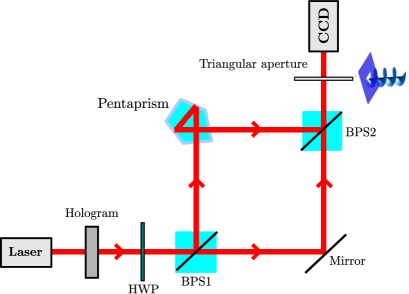
Our experimental proposal consists in submitting a light beam endowed with an arbitrary nonzero OAM to a modified Mach-Zehnder interferometer (MZI) composed by two polarizing beam splitter (PBS), in which horizontally- and vertically-polarized fields are respectively transmitted and reflected, a mirror, a pentaprism, and a charge-coupled-device (CCD) camera. In the experimental setup, which is sketched in Fig.1, the light beam will have the horizontally and vertically-polarized components separated by the first polarizing beam splitter, PBS1. The former will be deflected by 90∘ towards the second beam splitter PBS2, while the latter will reflect twice inside the pentaprism before being deviated. The net effect of the pentaprism is to deviate the light beam by 90∘ with high precision, facilitating the alignment of the interferometer, and invert the image, due to the double reflection, as described in Ref. Sasada and Okamoto (2003). This last fact causes an inversion in the OAM sign of the output beam that is also sent towards PBS2.
In order to understand the effect of the proposed optical circuit, let us investigate, for example, the transformations obtained in the evolution of an input beam that is horizontally-polarized and has an arbitrary OAM quantified by . After being transmitted through PBS1, the beam will be deflected in the mirror and sent towards PBS2 to be again transmitted and detected by the CCD camera. Note that the states of both polarization and OAM are unchanged in this lower arm of the interferometer. On the other hand, in considering a vertically-polarized input beam with an arbitrary OAM, , it will be reflected at PBS1 to be later deviated by the pentaprism with an inverted OAM, . This beam will then suffer a new reflection at PBS2 before being detected by the CCD camera.
Now, let us translate the overall effect of this optical circuit in terms of quantum logic operations. First, we adopt some basis states for the representation of polarization and OAM. The horizontally- and vertically-polarized states are and , respectively. In turn, positive and negative OAM states will be represented respectively by and . In this form, the basis states that span our four-dimensional space with the polarization and OAM of the photons are . Observe that, if we consider the polarization states as the control and the OAM state as the target, with the experimental proposal above, the four classical CNOT gate transformations are naturally implemented,
| (1) |
| (2) |
| (3) |
| (4) |
However, the optical circuit of Fig. 1 also serves as a quantum CNOT logic gate. Indeed, if one considers a general combination of the basis states,
| (5) |
the following transformation takes place:
| (6) |
where the coefficients , , and are arbitrary complex numbers, satisfying the normalization condition, . Eq. 6 is the necessary condition for the implementation of a quantum CNOT gate, i.e., if the control qubit is 0 (1), the target qubit is unchanged (changed).
Another interesting aspect related to the circuit of Fig. 1 is the possibility of creating entangled states involving the polarization and the OAM degree of freedom of a single-photon. This task can be realized if a Hadamard gate is applied to the control qubit (polarization) prior to the quantum CNOT gate Nielsen and Chuang (2011). In fact, with this procedure we are able to create maximally entangled Bell states involving the polarization and OAM Hilbert spaces. Therefore, what we need here is an optical element that acts as a Hadamard operation in the polarization state space. A waveplate placed before PBS1 that rotates the polarization by 45∘, would play this role. In this case, in considering both the polarization and OAM states, if the polarization of the incident light is horizontal (vertical), after the waveplate, it is transformed into a diagonal (antidiagonal) polarization, that is,
| (7) |
| (8) |
| (9) |
| (10) |
Therefore, after these operations, the transformed state will be submitted to the circuit of Fig. 1. The circuit will execute the CNOT operation given by the rules of Eqs. 1 to 4, producing the complete family of maximally entangled Bell states
| (11) |
| (12) |
| (13) |
| (14) |
which demonstrate the entangling properties of the proposed experimental setup.
A fundamental stage in implementing any quantum information protocol is obviously the readout process. In the present case, it is essential that the four basis states of Eqs. 1 to 4 be distinguishable in an experimental realization. The readout of the polarization basis states, and , is trivial with the usage of linear polarizers oriented along the horizontal and vertical directions. Nevertheless, the readout of the OAM basis states, and , is not so straightforward. Indeed, by direct detection of a light beam endowed with OAM, one can only see the well-known donut-shaped intensity profile, independent of the topological charge of the optical vortex Yao and Padgett (2011).
To circumvent this problem, we propose the observation of the far field pattern of the output beam after being diffracted by a triangular aperture. This method was proposed in Ref. Hickmann et al. (2010) as a practical and precise procedure to determine the OAM of optical fields. Specifically, it was found that the diffraction pattern is a triangular optical lattice whose number of bright points on any side of the triangle is related with the topological charge as . However, the readout process in our protocol does not require the knowledge about , but only its sign. This is where the triangular aperture method is more effective. The sign of , which is related to the handedness of the optical vortex, is found out just by observing the direction to which the triangular optical lattice is pointing. If the triangular lattice points to same direction of the triangular aperture is because the the sign of the OAM is positive, which means . Conversely, if the triangular lattice points to the opposite direction, it signifies that the OAM sign is negative, rendering . In this form, for the present setup, the triangular aperture should be placed before the CCD camera for the observation of the handedness of the output optical vortex.
III Experimental methods and results
We realized an experiment following the theoretical proposal sketched in Fig. 1. The light source used was the Gaussian mode of an Argon Laser operating at 532 nm with a power of 10 mW with vertical polarization. The beam then illuminates a CGH with controllable pixels written in an (Hamamatsu Model X10468-01) spatial light modulator (SLM) for the generation of the helical phase profile, . In our experiment, we created a beam with before PBS1. Next, the reflected beam is deviated by the pentaprism, which also inverts the sign of the OAM, to recombine with the beam transmitted by PBS1 at the second polarized beam splitter PBS2. After this stage, the output beam passes through an equilateral triangular aperture with side length of 2 mm. Then, a 30 cm focal length lens was placed immediately after the aperture to create the far field diffraction pattern at the focal length of the lens. Finally, the intensity diffraction pattern is registered by the CCD camera.
The preparation and measurement of the control qubit (polarization) is made by using a half-wave plate (HWP) before PBS1, if one wants to make the input polarization horizontal, and a linear polarizer placed after PBS2 oriented either along the vertical or the horizontal direction in order to verify the final control state.
| Input state | Output state |
|---|---|
| H polarization; | H polarization; |
| H polarization; | H polarization; |
| V polarization; | V polarization; |
| V polarization; | V polarization; |
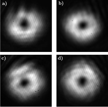
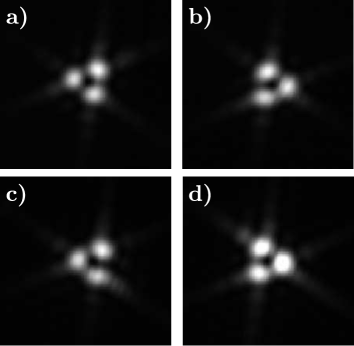
The target (OAM) state is measured according to the orientation of the triangular truncated optical lattice observed in the camera Hickmann et al. (2010). In order to see the efficiency of the method, in Fig. 2 we show the intensity patterns of the four output states of Eqs. 1 to 4 recorded by the camera when the triangular aperture is absent in the experiment. As can be seen, all we obtain is the characteristic donut-like intensity profile, without OAM state information. In a different perspective, Fig. 3 shows the pattern when the aperture is present. We observe that the states with and are easily distinguishable. Table I shows the truth table of our CNOT gate, whose output state profiles are shown in Fig. 3. The results completely agree with the transformations indicated in Eqs. 1 to 4.
IV Conclusion
To sum up, we theoretically and experimentally demonstrated a linear optical quantum CNOT gate involving the polarization and OAM degrees of freedom, which serve as the control and target qubits, respectively. The experimental setup does not demand the usage of computer generated holograms to process information; a fact that makes the arrangement suitable for scaling up quantum-computing architectures. The readout process is based only on the use of a linear polarizer and a diffractive triangular aperture. With the present configuration, the experimental results confirmed our theoretical predictions in an unambiguous way. Given the stability of the experimental setup and the robustness of the polarization and OAM states against environmental noise, we consider the present proposal a promising candidate to be used in future schemes of linear optical quantum computation.
Acknowledgements
The authors acknowledge the Brazilian funding agencies CNPq (AC’s Universal grant No. 423713/2016-7 & BLB’s PQ grant No. 309292/2016-6), CAPES and Alagoas state research agency FAPEAL. We also thank UFAL (AC’s and WCS’s paid license for scientific cooperation at UFRN and UFSC, respectively) and MEC/UFRN (AC’s postdoctoral fellowship).
References
- Nielsen and Chuang (2011) M. A. Nielsen and I. L. Chuang, Quantum Computation and Quantum Information: 10th Anniversary Edition, 10th ed. (Cambridge University Press, New York, NY, USA, 2011).
- Ekert (1991) A. K. Ekert, Phys. Rev. Lett. 67, 661 (1991).
- Bennett and Wiesner (1992) C. H. Bennett and S. J. Wiesner, Phys. Rev. Lett. 69, 2881 (1992).
- Bennett et al. (1993) C. H. Bennett, G. Brassard, C. Crépeau, R. Jozsa, A. Peres, and W. K. Wootters, Phys. Rev. Lett. 70, 1895 (1993).
- Knill et al. (2001) E. Knill, R. Laflamme, and G. J. Milburn, Nature 409, 46 EP (2001), article.
- Bouwmeester et al. (2010) D. Bouwmeester, A. K. Ekert, and A. Zeilinger, The Physics of Quantum Information: Quantum Cryptography, Quantum Teleportation, Quantum Computation, 1st ed. (Springer Publishing Company, Incorporated, 2010).
- Shor (1997) P. W. Shor, SIAM J. Comput. 26, 1484 (1997).
- Lanyon et al. (2007) B. P. Lanyon, T. J. Weinhold, N. K. Langford, M. Barbieri, D. F. V. James, A. Gilchrist, and A. G. White, Phys. Rev. Lett. 99, 250505 (2007).
- Zurek (2003) W. H. Zurek, Rev. Mod. Phys. 75, 715 (2003).
- Schlosshauer (2005) M. Schlosshauer, Rev. Mod. Phys. 76, 1267 (2005).
- de Lima Bernardo (2017) B. de Lima Bernardo, Physics Letters A 381, 2239 (2017).
- Balthazar et al. (2016) W. F. Balthazar, C. E. R. Souza, D. P. Caetano, E. F. G. ao, J. A. O. Huguenin, and A. Z. Khoury, Opt. Lett. 41, 5797 (2016).
- Balthazar et al. (2014) W. F. Balthazar, D. P. Caetano, C. E. R. Souza, and J. A. O. Huguenin, Brazilian Journal of Physics 44, 658 (2014).
- Balthazar et al. (2015) W. F. Balthazar, M. H. M. Passos, A. G. M. Schmidt, D. P. Caetano, and J. A. O. Huguenin, Journal of Physics B: Atomic, Molecular and Optical Physics 48, 165505 (2015).
- DiVincenzo (1995) D. P. DiVincenzo, Phys. Rev. A 51, 1015 (1995).
- Kok and Lovett (2010) P. Kok and B. W. Lovett, Introduction to Optical Quantum Information Processing (Cambridge University Press, 2010).
- Kok et al. (2007) P. Kok, W. J. Munro, K. Nemoto, T. C. Ralph, J. P. Dowling, and G. J. Milburn, Rev. Mod. Phys. 79, 135 (2007).
- Fiorentino and Wong (2004) M. Fiorentino and F. N. C. Wong, Phys. Rev. Lett. 93, 070502 (2004).
- de Oliveira et al. (2005) A. N. de Oliveira, S. P. Walborn, and C. H. Monken, Journal of Optics B: Quantum and Semiclassical Optics 7, 288 (2005).
- Deng et al. (2007) L.-P. Deng, H. Wang, and K. Wang, J. Opt. Soc. Am. B 24, 2517 (2007).
- Zeng et al. (2016) Q. Zeng, T. Li, X. Song, and X. Zhang, Opt. Express 24, 8186 (2016).
- Hickmann et al. (2010) J. M. Hickmann, E. J. S. Fonseca, W. C. Soares, and S. Chávez-Cerda, Phys. Rev. Lett. 105, 053904 (2010).
- Allen et al. (1992) L. Allen, M. W. Beijersbergen, R. J. C. Spreeuw, and J. P. Woerdman, Phys. Rev. A 45, 8185 (1992).
- Yao and Padgett (2011) A. M. Yao and M. J. Padgett, Adv. Opt. Photon. 3, 161 (2011).
- Barreiro et al. (2008) J. T. Barreiro, T.-C. Wei, and P. G. Kwiat (2008).
- Malik et al. (2016) M. Malik, M. Erhard, M. Huber, M. Krenn, R. Fickler, and A. Zeilinger, Nature Photonics 10, 248 EP (2016).
- Fickler et al. (2016) R. Fickler, G. Campbell, B. Buchler, P. K. Lam, and A. Zeilinger, Proceedings of the National Academy of Sciences 113, 13642 (2016), http://www.pnas.org/content/113/48/13642.full.pdf .
- Sasada and Okamoto (2003) H. Sasada and M. Okamoto, Phys. Rev. A 68, 012323 (2003).