Send correspondence to D. Barkats, 60 Garden Street, MS 42, Cambridge, MA 02138 USA. E-mail: dbarkats@cfa.harvard.edu
Ultra-Thin Large-Aperture Vacuum Windows for Millimeter Wavelengths Receivers
Abstract
Targeting faint polarization patterns arising from Primordial Gravitational Waves in the Cosmic Microwave Background
requires excellent observational sensitivity. Optical elements in small aperture experiments such as Bicep3 and Keck Array are designed to
optimize throughput and minimize losses from transmission, reflection and scattering at millimeter wavelengths. As aperture size increases, cryostat vacuum windows must withstand larger forces from atmospheric pressure and the solution has often led to a thicker window at the expense of larger transmission loss. We have identified a new candidate material for the fabrication of vacuum
windows: with a tensile strength two orders of magnitude larger than previously used materials,
woven high-modulus polyethylene could allow for dramatically thinner windows, and therefore significantly reduced
losses and higher sensitivity. In these proceedings we investigate the suitability of high-modulus polyethylene windows for ground-based CMB experiments, such as current and future receivers in the Bicep/Keck Array program. This includes characterizing their optical transmission as well as their mechanical behavior under atmospheric pressure. We find that such ultra-thin materials are promising candidates to improve the performance of large-aperture instruments at millimeter wavelengths, and outline a plan for further tests ahead of a possible upcoming field deployment of such a science-grade window.
keywords:
Millimeter Wavelengths, Vacuum Windows, Polymer Materials, Cosmic Microwave Background, Primordial Gravitational Waves, Polarization, BICEP, Keck Array1 INTRODUCTION
Many ground-based millimeter-wave receivers, such as those targeting the 2.7 K Cosmic Microwave Background (CMB), are designed around cryogenically cooled detectors and optics. Cryogenic receivers therefore include a vacuum window that separates cold components under vacuum from ambient air. Materials suitable for the fabrication of such windows must withstand the force developed by atmospheric pressure over the large area of the clear optical aperture, and minimize optical loading (transmission loss, reflections and scattering). These specifications lead to conflicting solutions, as strong materials are typically not transparent in-band (Kevlar®, Dacron®, carbon fiber, composites), while transparent materials have comparatively low bulk modulus and tensile strength (Polyethylene, Polypropylene, Teflon). CMB experiments so far have found a compromise by using various forms of polyethylene.
Zotefoam®111http://www.zotefoams.com/ (HD30, PPA30), a Nitrogen-expanded polyethylene closed-cell foam, has been employed for experiments with aperture sizes smaller than (e.g. Bicep1 [1], Bicep2 [2], Keck Array [3], SPT-SZ [4], SPTpol [5], ACBAR [6], PolarBear [7]). Zotefoam® has been used successfully in stacks up to 5” thick for windows up to 13” in diameter. With in-band transmission exceeding % and low index of refraction , no anti-reflective (AR) coating is necessary. This made Zotefoam® an ideal candidate for mm-wave windows. However, scaling to larger diameter and thicker layers has proved too cumbersome.
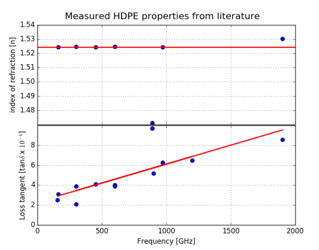
For larger apertures, where the required thickness of Zotefoam® would become unwieldy, slabs of bulk high-density polyethylene or ultra-high molecular weight polyethylene (HDPE and UHMWPE) have been the default solution (e.g. for Bicep3 [8, 9], Abs [10], SPT-3G [11], Class [12], QUIET [13], ACT-MBAC [14], ACTPol and AdvACT [15]). The transmission properties of these materials have been studied in the lab (e.g. [16]) and their loss is known to scale with the thickness. With an index , antireflection-coating becomes necessary to minimize reflection losses.
 |
|
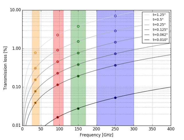
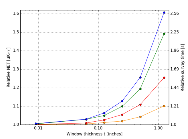
To achieve ever-increasing sensitivities, CMB experiments depend on a steady increase in optical throughput (more detectors in the focal plane and larger focal planes), which naturally translates into larger optical apertures. The thickness of HDPE/UHMWPE slabs used as vacuum windows must increase accordingly in order to withstand larger forces from atmospheric pressure. Figure 1 shows the dependence of transmission loss and relative sensitivity on nominal window thickness, for different observing frequencies assuming the standard bulk polyethylene windows. The Noise-Equivalent-Temperature (NET) is a steep function of window thickness, especially at higher frequencies. Above 100 GHz, even a modest thickness of HDPE significantly affects the sensitivity on the sky, as the window begins to contribute significantly to the total optical loading on the detectors. ‘Stage 3’ CMB experiments are planning receivers with apertures in excess of 60 cm (for example Bicep Array’s 28” diameter receivers) with several bandpasses up to 270 GHz. Improvements in vacuum window design and fabrication are necessary in order to prevent degradation in sensitivity as observations push to higher frequencies.
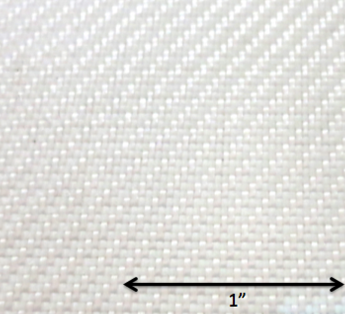
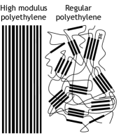
Since the 1990s, advancements in gel spinning technology have allowed the commercial development of spun UHMWPE fibers known as Dyneema®222Dyneema® is a regisitered trademark of Royal DSM N.V. or Spectra®333Spectra® is a regisitered trademark of Honeywell International.. For the rest of this paper, we refer to these fibers as High Modulus Polyethylene (HMPE). Extruding UHMWPE gel through a spinneret at a carefully controlled temperature leads to a high degree of molecular chain alignment (see Figure 2). The alignment of the fibers, or crystallinity, yields a quoted tensile modulus and tensile strength approximately 100 times higher than that of the bulk UHMWPE. The tensile strength of HDPE is typically between 20 and 40 MPa while that of HMPE is 1-4 GPa [18, 19, 20, 21]. Thin, fabric-like sheets can be woven from individual fibers and coated to prevent fraying. With a strength-to-weight ratio exceeding that of steel by a factor of approximately 10, industrial applications of HMPE have included radomes, ballistics protection, lightweight link chains and a wide range of technical fabrics.
|
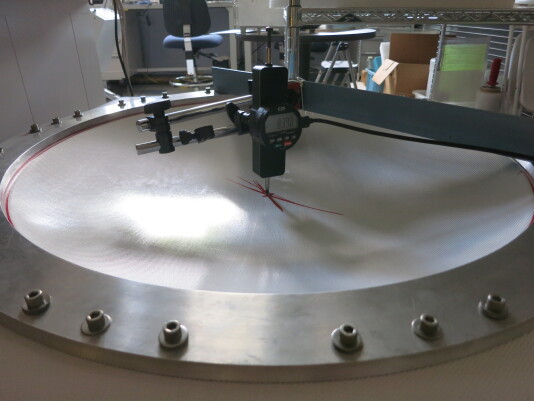
Since these HMPE fibers are fabricated from Ultra High Molecular Weight Polyethylene, we expect they might have similar refractive index and loss tangent at millimeter wavelengths as the bulk material. The combination of increased strength and likely suitable optical properties presents the potential of dramatically thinner (and therefore more transparent) vacuum windows. Here we present initial results of an investigation aiming to test the relevant mechanical and optical characteristics of windows made of woven HMPE fabric. An example prototype with 27” clear aperture is shown under test on a vacuum chamber in Figure 2. The woven-like nature of the ‘raw’ HMPE fabric requires further custom processes to laminate it with other plastics to obtain a vacuum tight surface, to prevent fraying, and to transform the woven matrix into an optically homogeneous material.
The outline of these proceedings is as follows. In Section 2 we present tests aiming to validate the high tensile characteristics of the HMPE fibers and to investigate the behavior of prototype windows placed under atmospheric pressure for long periods of time. We have experimented with various fabrication processes and are therefore including results for different samples and prototypes. Throughout these proceedings we use the term ‘raw Dyneema®’ or ‘raw HMPE’ to refer to the unlaminated woven fabric of high modulus fibers as received from the manufacturer. The samples referred to as ‘single layer’ or ‘double layers’ are made of one or more layers of raw HMPE fabric laminated in between thin layers of LDPE on either side. We are also experimenting with a different form of non-woven HMPE fabric, which we refer to as ‘CT10’, consisting of wider flat-pressed sheets of HMPE laminated together. We note that we are still optimizing the window fabrication process and do not discuss the details here. In Section 3 we present results from reflection spectra of HMPE samples that confirm their index of refraction is consistent with that of bulk UHMWPE. Section 4 describes plans for future work paving the way to a full technology demonstration and eventual field deployment of a large-aperture HMPE window on BICEP3 at the South Pole. Section 5 summarizes our Conclusions.
2 Mechanical Properties of HMPE Window Prototypes
 |
The first step in assessing the suitability of woven HMPE fabric for vacuum windows is to understand its behavior when placed under mechanical stress. We carried out different types of tests, with the aim to:
-
•
confirm the manufacturer-quoted tensile properties of these HMPE fibers,
-
•
compare it to previously used materials (bulk HDPE/UHMWPE),
-
•
and assess the long-term behavior of realistic science-grade windows under realistic operating conditions.
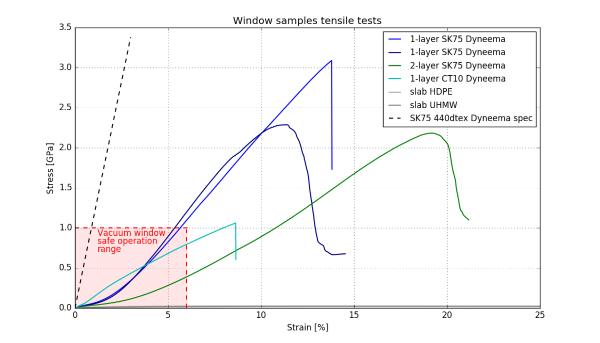
As a first step, we measure the stress-strain relationship of different HMPE window variants and compare them to manufacturer specification and to reference bulk HDPE/UHMWPE samples. We obtain curves for force (in Newtons) vs. extension (in mm) using an Instron®444http://www.instron.us/ testing system. Those curves are then converted to stress (in units of Pascals) vs. strain (in %) based on the measured lengths and cross-sectional area of our samples. We note that it is critical to carefully account for the correct cross-sectional area of the fabric based on its matrix structure, not on its bulk properties treating it as a homogeneous material. Figure 3 presents representative profiles for our different types of samples. The resulting modulus, yield stress and yield strain values are summarized in Table 1. We find that the yield strength (the maximum stress on the curves just before failure) for our laminated single-layer sample closely matches the manufacturer-quoted specification for the HMPE yarn. We also find that all our laminated samples are more elastic (lower Young’s modulus and higher strain at yield) than the specification for the single yarn. This result is not unexpected. Compared to a individual yarns, the woven structure of the HMPE fabric tends to straighten itself under tension, yielding more elastic properties than the individual yarn. We also tested 2-layer laminates samples. We confirmed that the holding force scales with cross section (yield strength in Pa remained equal for 1- and 2-layer laminates) but noted an unexpected increase in elasticity. We suspect this is caused by imperfect bonding between the two woven fabric layers and are still exploring the optimal bonding procedure to reduce this effect. In the end, all our tested HMPE woven laminates were significantly stronger and stiffer than the bulk HDPE/UHMWPE (whose stress vs. strain curves are barely visible near the bottom of Figure 3). For vacuum window applications, we plan to fabricate windows that remain well within the elastic deformation regime, approximately below 1 GPa stress and 6% strain for the samples tested.
| Material | Tensile modulus [GPa] | Yield stress [GPa] | Strain at yield [%] |
|---|---|---|---|
| Dyneema® spec | 113 | 3.4 | 3.5 |
| 1-layer woven HMPE fabric | 26.9 | 3.1 | 11.9 |
| 2-layer woven HMPE fabric | 14.3 | 2.2 | 16.4 |
| 1-layer CT10 fabric | 11.9 | 1.1 | 9.3 |
| Bulk HDPE | 0.9 | 0.025 | 10 |
| Bulk UHMWPE | 0.7 | 0.022 | 30 |
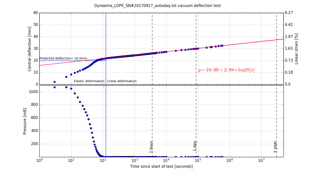 |
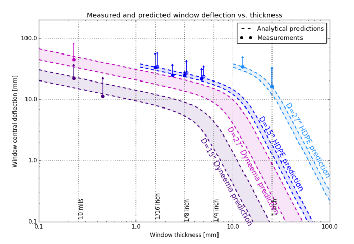
Moving beyond unit-level verification of material properties, we seek to assess the long term creep (visco-elastic deformation) of realistic science-grade windows under operating conditions. We have at our disposal two test vacuum chamber with 15” and 27” diameter aperture. The 27”-diameter chamber nearly matches the diameter of Bicep3 and planned Bicep Array receiver windows and therefore provides an ideal testing setup for those future windows. Figure 4 shows the results of a long duration test where a prototype single-layer woven HMPE, 15”-diameter window was placed under vacuum for several months. Initially the window deflects suddenly as a result of the rapid pressure drop. Once the pressure inside the chamber stabilizes to a low value ( mBar), the window experiences the maximum force from atmospheric pressure and continues to deform logarithmically in time. In this creep deformation regime, we can extrapolate the deflection to a full year and show it remains well within the safe operating zone outlined in Figure 3 (strain ). We have tested many windows, including thicker bulk HDPE and thin laminated woven HMPE fabrics, for durations ranging from 1 week to 6 months, on our 15” and 27”-diameter test chambers and the results are summarized in Figure 5.
|
Figure 5 (left) shows the measured initial deflections (solid circles), the extrapolated deflection after 1 year (arrows), and the analytical deflection predictions (dashed bands). The agreement between the measured initial deflection and the simple analytical expectation is excellent. The deflection due to creep is not accounted for in the calculation. The analytical predictions for deflection follow the model given by Equation 1 from [22]:
| (1) |
where , , and are the window material central deflection, thickness, and radius in meters, is the material’s unitless Poisson’s ratio, is the pressure differential on the window, and is the material’s (flexural or tensile) modulus. We can see that in the linear regime of small deflection to thickness ratio (bottom right of Figure 5 left panel), the deflection scales as
| (2) |
At the other end of the spectrum, in the regime of large deflection to thickness ratio (top left of Figure 5 left panel), the deflection scales as
| (3) |
The windows made of ultra-thin HMPE woven laminates presented here are taking advantage of this latter regime where the deflection increases more slowly with thickness. With a 27”-diameter aperture, we have indeed obtained similar deflections with 0.5”-thick HDPE ( mm) as with a 0.010”-thick woven HMPE laminated window ( mm).
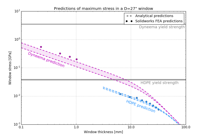
We also compute analytical predictions for the maximum stress experienced by these windows. The equations for stress are also taken from [22] and can be written as simple expressions in the two limiting cases. In the regime with large deflection to thickness ratio, we have
| (4) |
and in the regime of large deflection to thickness, we obtain
| (5) |
where is a unitless factor between 0 and 1, and is the maximum stress on the window. The stress predictions for a nominal 27”-diameter window are shown in the right panel of Figure 5 for both bulk HDPE and HMPE. The colors correspond to those used for the deflection curves on the left side of Figure 5. The analytical curves are truncated at a nominal safety factor of two (where the stress reaches half the nominal yield strength of the material). We have taken the yield strength of HDPE to be 40 MPa and that of HMPE to be 3.5 GPa. To form complete curves, we have combined the expressions for the two limiting cases in inverse quadrature. We validate the analytical predictions of stress with accompanying Finite Element Analysis (FEA) simulations and find good agreement in the overall shape. These predictions indicate that for 27”-diameter, a 0.010”- to 0.050”-thick HMPE window will nominally provide a larger safety factor than ” to ”-thick HDPE/UHMWPE window. We also note that these simulations and deflection tests were all performed with sea level atmospheric pressure of 14.7 psi (1013 mBar). Actual deployment on an instrument at the South Pole will have significantly less mechanical loading. (The South Pole atmospheric pressure is 9.7 psi or 670 mBar.)
3 Optical Properties of HMPE Samples
 |
 |
Ensuring the mechanical resilience of vacuum windows is critical for overall system safety. For HMPE windows, characterizing the expected optical transmission loss and the possible scattering associated with these new materials is also essential. Optimal millimeter-wave vacuum windows must have minimal bulk loss as well as low reflectivity and scattering. Reflected light can be minimized through the application of an AR coating layer, with thickness and an index of refraction approximately equal to the square root of that of the bulk material. For example, layers of expanded Teflon () on either side of an UHMWPE () window can reduce the band-averaged reflections to less than 1%. Since the HMPE fabric windows we are testing are made from woven fibers of UHMWPE, we hypothesize that their index of refraction and transmissivity may be similar to a thin layer of bulk UHMWPE. Here we present reflection tests carried out with the aim of:
-
•
confirming high transmission consistent with that of UHMWPE, and
-
•
demonstrating we can minimize reflectivity through the application of an AR coat.
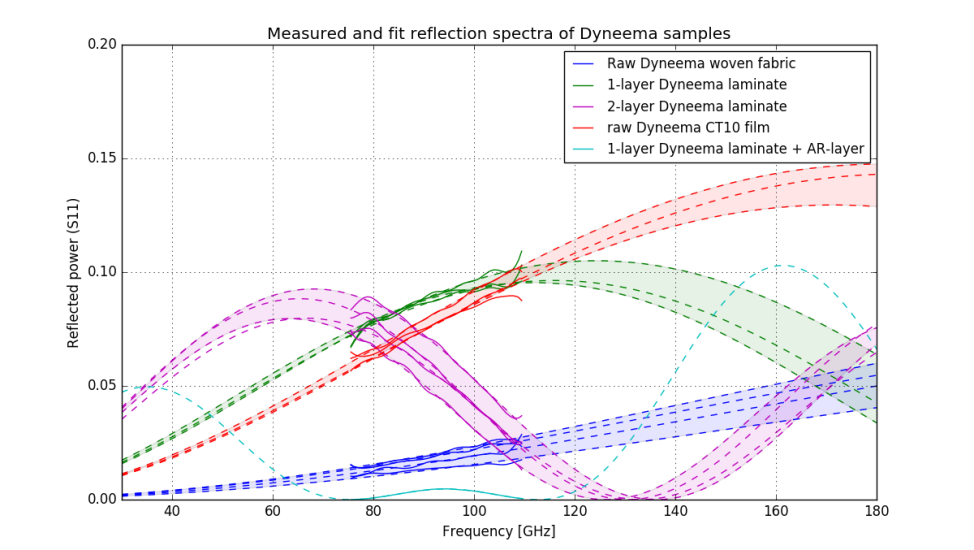
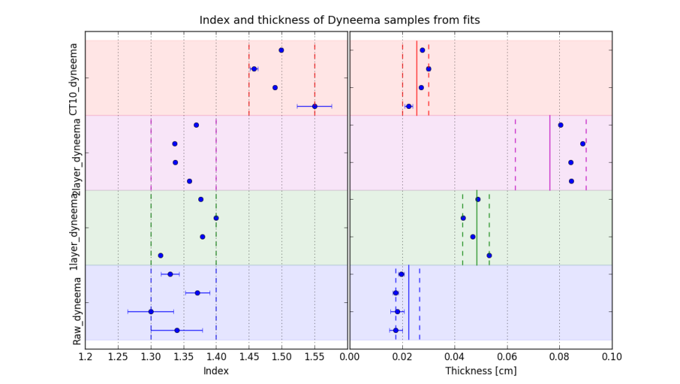
We use a Vector Network Analyzer (VNA) to produce a frequency sweep from 75 to 110 GHz and measure the reflected spectra (S11) from various HMPE window samples. The signal is coupled to free space with a standard gain horn, and the beam is then collimated with a refocusing mirror. The samples are placed in the near-field of the collimating optics to obtain nearly-orthogonal angles of incidence on the sample. The samples are carefully tensioned in a stretching device in order to produce a flat, repeatable surface of incidence. In addition to the standard in-waveguide short/load calibration, we apply a time-domain gating filter to the measured S11 response to isolate the free space reflections from our samples. For the raw, one-layer and two-layer samples, data is acquired multiple times from distinct samples from the same batch, in order to evaluate measurement error and sample-to-sample variations. The resulting spectra are shown in Figure 6. We also include the reflection spectrum measured for a single-layer sample laminated with an expanded Teflon (Teadit®) AR coating layer. The data are fit with a theoretical spectrum for a stratified medium computed with the transfer matrix method.
From these fits, we recover the thickness and index of refraction for each sample and show the results in Figure 6. All three woven HMPE fabric samples (raw, single- and double-layer) present an index , somewhat lower than the expectation for bulk UHMWPE (). This low index is indeed consistent with the density of the woven HMPE fabric, whether laminated or not. Measurements of the density suggest a 40-60% fill factor. This interpretation is reasonable given the interweaving of fibers in the fabric is expected to give rise to voids. We expect the recovered density and index of refraction to strongly depend on the lamination process parameters (temperature, pressure, and time) and this dependence is still under investigation. Altogether, our reflection measurements confirm that the reflection characteristics of woven HMPE fabric are similar to those of the bulk UHMWPE material. We expect the (more difficult to measure) transmission loss to yield similar results. We also demonstrate that the in-band reflected power can be strongly reduced through the application of a standard AR layer. One additional advantage of these ultra-thin laminated windows is that their intrinsic thickness can be tuned ahead of AR coating to minimize reflections around a particular frequency. In combination with standard AR layers, this can produce low reflections over very wide bandwidths. We eventually plan to extend these free space reflectivity tests down to 30 GHz and up to 270 GHz to cover the expected bandpasses of Bicep Array receivers.
4 Future Work and Pathway to Field Deployment
Further characterization of both the mechanical behavior and optical properties of these woven HMPE windows is needed prior to field deployment. Beyond the results presented in these proceedings, here we outline ongoing and future tests to be carried out before integration into a working receiver.
4.1 Testing and Optimization of Mechanical Properties
The next step is to scale up the testing effort in order to replicate the full Bicep3 and Bicep Array aperture size and flange design in the lab. In parallel, we plan to carry out long duration tests in order to study the creep and deflection behavior over longer ( months) timescales than those shown in Figure 4. Another area of interest for the windows featuring multiple layers of HMPE is the effect of fiber alignment. Because of the woven matrix structure of these fabrics, they mainly withstand stress in two orthogonal directions, whereas a window under load develops forces in all radial directions. We are therefore in the process of investigating the advantages and drawbacks of laminating multiple layers at different angles from each other, compared to co-aligning all layers. Preliminary tests suggest that co-alignment of the fibers allows for higher yield stresses, likely because it helps maintain layer cohesion. However, these results must be confirmed once the lamination process parameters are optimized. Further validations needed prior to field deployment include investigating cold temperature creep behavior, leak rates, UV-light stability, and failure modes during destructive testing. While many of these properties are already known and largely satisfactory for the HMPE fiber itself [20], we nevertheless plan further tests of the most important properties to our application. We also note that the combination of lower atmospheric pressure at the South Pole and the lower operating temperature of the windows are both expected to significantly decrease HMPE fiber creep rate, possibly by 1-2 orders of magnitude [23] compared to lab conditions, and therefore contribute to increasing the lifetime of the window.
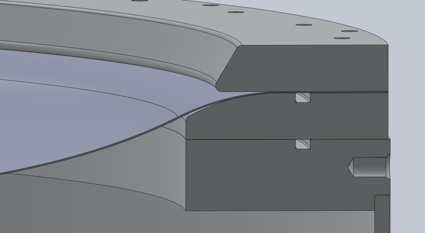
In a parallel effort, we are working to optimize the design of the vacuum window flanges. The large force of atmospheric pressure directed downward on the window can cause it to slip inwards and accumulate high stresses around the clamping points. As a result, we are experimenting with special clamping features in order to improve gripping forces on the plastic surface, for example using different designs of knurling and serrations. Another aspect of frame design we are currently examining is the transition from supported to unsupported surfaces around the window edge. At those locations, the windows experience a steep sudden deflection that can cause stress accumulation. A smoother transition with optimal curvature to match the natural launch angle of the deflected window will contribute to reduced shear in thicker materials, and reduced stress concentrations around the edge. Figure 7 shows an example design of window frame and clamp where the edge of the HMPE window under load conforms to a curved flange.
 |
4.2 Optical Characterization
Along with loss due to absorption and reflection, scattering from optical elements is detrimental as it increases loading and can introduce systematic noise in CMB observations if the scattered light is not properly baffled. The woven, mesh-like nature of these HMPE windows could conceivably introduce additional scattering compared to homogeneous UHWMPE. We are investigating this possibility using two complementary approaches. During the 2017-2018 austral summer, data was gathered with prototype raw, 1-layer, 2-layer HMPE windows placed in front of the Bicep3 and Keck Array receivers at 95, 210 and 270 GHz. The procedure included datasets which should enable us to constrain the integrated scattered radiation. Secondly, we plan to measure scattered spectra at different angles away from standard specular reflection in the lab with a VNA. We specifically wish to test the hypothesis that samples laminated and filled in with LDPE will appear optically more homogeneous to radiation and therefore exhibit weaker scattering than the raw material. Finally, the crystalline woven nature of the HMPE fabric may introduce polarization effects. We are planning to characterize the polarization-dependent index of refraction of the HMPE windows and to confirm that it is not birefringent on the large scales probed by the beams of the Bicep/Keck telescopes.
5 Conclusions
For experiments with photon-limited detectors, probing the faint polarization patterns in the CMB requires ever-increasing sensitivity and therefore expanding focal plane arrays. The aperture size of CMB telescopes has been growing, driving the need for new technology development. In particular, future large-aperture receivers will have to meet the challenge of fabricating larger optical elements that retain structural integrity without introducing prohibitively large losses. Ultra-thin windows made from woven high modulus fibers of UHMWPE are promising candidates for large-aperture receivers operating at millimeter wavelengths. By providing an order of magnitude reduction in loss from the window, they could lead to a significant reduction in the photon loading from the instrument and therefore an improvement in sensitivity. We have presented the initial mechanical and optical system-level tests that are currently underway in order to vet these new materials for use in CMB receivers. Provided our continued testing of prototypes is successful, we plan to deploy a science-grade multi-layer woven HMPE window on the Bicep3 receiver in the coming year. We expect that replacing the current 1.25”-thick slab HDPE with a new multi-layer woven HMPE window will improve the sensitivity by 25%.
References
- [1] Yoon, K. W., Ade, P. A. R., Barkats, D., Battle, J. O., Bierman, E. M., Bock, J. J., Brevik, J. A., Chiang, H. C., Crites, A., Dowell, C. D., Duband, L., Griffin, G. S., Hivon, E. F., Holzapfel, W. L., Hristov, V. V., Keating, B. G., Kovac, J. M., Kuo, C. L., Lange, A. E., Leitch, E. M., Mason, P. V., Nguyen, H. T., Ponthieu, N., Takahashi, Y. D., Renbarger, T., Weintraub, L. C., and Woolsey, D., “The Robinson Gravitational Wave Background Telescope (BICEP): a bolometric large angular scale CMB polarimeter,” in [Society of Photo-Optical Instrumentation Engineers (SPIE) Conference Series ], Proc. SPIE 6275, 62751K (June 2006). http://adsabs.harvard.edu/abs/2006SPIE.6275E..1KY.
- [2] BICEP2 Collaboration, Ade, P. A. R., Aikin, R. W., Amiri, M., Barkats, D., Benton, S. J., Bischoff, C. A., Bock, J. J., Brevik, J. A., Buder, I., Bullock, E., Davis, G., Day, P. K., Dowell, C. D., Duband, L., Filippini, J. P., Fliescher, S., Golwala, S. R., Halpern, M., Hasselfield, M., Hildebrandt, S. R., Hilton, G. C., Irwin, K. D., Karkare, K. S., Kaufman, J. P., Keating, B. G., Kernasovskiy, S. A., Kovac, J. M., Kuo, C. L., Leitch, E. M., Llombart, N., Lueker, M., Netterfield, C. B., Nguyen, H. T., O’Brient, R., Ogburn, IV, R. W., Orlando, A., Pryke, C., Reintsema, C. D., Richter, S., Schwarz, R., Sheehy, C. D., Staniszewski, Z. K., Story, K. T., Sudiwala, R. V., Teply, G. P., Tolan, J. E., Turner, A. D., Vieregg, A. G., Wilson, P., Wong, C. L., and Yoon, K. W., “BICEP2. II. Experiment and three-year Data Set,” Astrophysical Journal 792, 62 (Sept. 2014). http://adsabs.harvard.edu/abs/2014ApJ...792...62B.
- [3] Vieregg, A. G., Ade, P. A. R., Aikin, R., Bischoff, C., Bock, J. J., Bonetti, J. A., Bradford, K. J., Brevik, J. A., Dowell, C. D., Duband, L., Filippini, J. P., Fliescher, S., Golwala, S. R., Gordon, M. S., Halpern, M., Hilton, G., Hristov, V. V., Irwin, K., Kernasovskiy, S., Kovac, J. M., Kuo, C. L., Leitch, E., Lueker, M., Montroy, T., Netterfield, C. B., Nguyen, H. T., O’Brient, R., Ogburn, R. W., Pryke, C., Ruhl, J. E., Runyan, M., Schwarz, R., Sheehy, C., Staniszewski, Z., Sudiwala, R., Teply, G., Tolan, J., Turner, A. D., Wilson, P., and Wong, C. L., “Optical characterization of the Keck array polarimeter at the South Pole,” in [Millimeter, Submillimeter, and Far-Infrared Detectors and Instrumentation for Astronomy VI ], Proc. SPIE 8452, 845226 (Sept. 2012). http://adsabs.harvard.edu/abs/2012SPIE.8452E..26V.
- [4] Carlstrom, J. E., Ade, P. A. R., Aird, K. A., Benson, B. A., Bleem, L. E., Busetti, S., Chang, C. L., Chauvin, E., Cho, H.-M., Crawford, T. M., Crites, A. T., Dobbs, M. A., Halverson, N. W., Heimsath, S., Holzapfel, W. L., Hrubes, J. D., Joy, M., Keisler, R., Lanting, T. M., Lee, A. T., Leitch, E. M., Leong, J., Lu, W., Lueker, M., Luong-Van, D., McMahon, J. J., Mehl, J., Meyer, S. S., Mohr, J. J., Montroy, T. E., Padin, S., Plagge, T., Pryke, C., Ruhl, J. E., Schaffer, K. K., Schwan, D., Shirokoff, E., Spieler, H. G., Staniszewski, Z., Stark, A. A., Tucker, C., Vanderlinde, K., Vieira, J. D., and Williamson, R., “The 10 Meter South Pole Telescope,” Publications of the Astronomical Society of the Pacific 123, 568 (May 2011). http://adsabs.harvard.edu/abs/2011PASP..123..568C.
- [5] Austermann, J. E., Aird, K. A., Beall, J. A., Becker, D., Bender, A., Benson, B. A., Bleem, L. E., Britton, J., Carlstrom, J. E., Chang, C. L., Chiang, H. C., Cho, H.-M., Crawford, T. M., Crites, A. T., Datesman, A., de Haan, T., Dobbs, M. A., George, E. M., Halverson, N. W., Harrington, N., Henning, J. W., Hilton, G. C., Holder, G. P., Holzapfel, W. L., Hoover, S., Huang, N., Hubmayr, J., Irwin, K. D., Keisler, R., Kennedy, J., Knox, L., Lee, A. T., Leitch, E., Li, D., Lueker, M., Marrone, D. P., McMahon, J. J., Mehl, J., Meyer, S. S., Montroy, T. E., Natoli, T., Nibarger, J. P., Niemack, M. D., Novosad, V., Padin, S., Pryke, C., Reichardt, C. L., Ruhl, J. E., Saliwanchik, B. R., Sayre, J. T., Schaffer, K. K., Shirokoff, E., Stark, A. A., Story, K., Vanderlinde, K., Vieira, J. D., Wang, G., Williamson, R., Yefremenko, V., Yoon, K. W., and Zahn, O., “SPTpol: an instrument for CMB polarization measurements with the South Pole Telescope,” in [Millimeter, Submillimeter, and Far-Infrared Detectors and Instrumentation for Astronomy VI ], Proc. SPIE 8452, 84521E (Sept. 2012). http://adsabs.harvard.edu/abs/2012SPIE.8452E..1EA.
- [6] Runyan, M. C., Ade, P. A. R., Bhatia, R. S., Bock, J. J., Daub, M. D., Goldstein, J. H., Haynes, C. V., Holzapfel, W. L., Kuo, C. L., Lange, A. E., Leong, J., Lueker, M., Newcomb, M., Peterson, J. B., Reichardt, C., Ruhl, J., Sirbi, G., Torbet, E., Tucker, C., Turner, A. D., and Woolsey, D., “ACBAR: The Arcminute Cosmology Bolometer Array Receiver,” Astrophysical Journal Supplement Series 149, 265–287 (Dec. 2003). http://adsabs.harvard.edu/abs/2003ApJS..149..265R.
- [7] Kermish, Z. D., Ade, P., Anthony, A., Arnold, K., Barron, D., Boettger, D., Borrill, J., Chapman, S., Chinone, Y., Dobbs, M. A., Errard, J., Fabbian, G., Flanigan, D., Fuller, G., Ghribi, A., Grainger, W., Halverson, N., Hasegawa, M., Hattori, K., Hazumi, M., Holzapfel, W. L., Howard, J., Hyland, P., Jaffe, A., Keating, B., Kisner, T., Lee, A. T., Le Jeune, M., Linder, E., Lungu, M., Matsuda, F., Matsumura, T., Meng, X., Miller, N. J., Morii, H., Moyerman, S., Myers, M. J., Nishino, H., Paar, H., Quealy, E., Reichardt, C. L., Richards, P. L., Ross, C., Shimizu, A., Shimon, M., Shimmin, C., Sholl, M., Siritanasak, P., Spieler, H., Stebor, N., Steinbach, B., Stompor, R., Suzuki, A., Tomaru, T., Tucker, C., and Zahn, O., “The POLARBEAR experiment,” in [Millimeter, Submillimeter, and Far-Infrared Detectors and Instrumentation for Astronomy VI ], Proc. SPIE 8452, 84521C (Sept. 2012). http://adsabs.harvard.edu/abs/2012SPIE.8452E..1CK.
- [8] Ahmed, Z., Amiri, M., Benton, S. J., Bock, J. J., Bowens-Rubin, R., Buder, I., Bullock, E., Connors, J., Filippini, J. P., Grayson, J. A., Halpern, M., Hilton, G. C., Hristov, V. V., Hui, H., Irwin, K. D., Kang, J., Karkare, K. S., Karpel, E., Kovac, J. M., Kuo, C. L., Netterfield, C. B., Nguyen, H. T., O’Brient, R., Ogburn, R. W., Pryke, C., Reintsema, C. D., Richter, S., Thompson, K. L., Turner, A. D., Vieregg, A. G., Wu, W. L. K., and Yoon, K. W., “BICEP3: a 95GHz refracting telescope for degree-scale CMB polarization,” in [Millimeter, Submillimeter, and Far-Infrared Detectors and Instrumentation for Astronomy VII ], Proc. SPIE 9153, 91531N (Aug. 2014). urlhttp://adsabs.harvard.edu/abs/2014SPIE.9153E..1NA.
- [9] Grayson, J. A., Ade, P. A. R., Ahmed, Z., Alexander, K. D., Amiri, M., Barkats, D., Benton, S. J., Bischoff, C. A., Bock, J. J., Boenish, H., Bowens-Rubin, R., Buder, I., Bullock, E., Buza, V., Connors, J., Filippini, J. P., Fliescher, S., Halpern, M., Harrison, S., Hilton, G. C., Hristov, V. V., Hui, H., Irwin, K. D., Kang, J., Karkare, K. S., Karpel, E., Kefeli, S., Kernasovskiy, S. A., Kovac, J. M., Kuo, C. L., Leitch, E. M., Lueker, M., Megerian, K. G., Monticue, V., Namikawa, T., Netterfield, C. B., Nguyen, H. T., O’Brient, R., Ogburn, R. W., Pryke, C., Reintsema, C. D., Richter, S., Schwarz, R., Sorenson, C., Sheehy, C. D., Staniszewski, Z. K., Steinbach, B., Teply, G. P., Thompson, K. L., Tolan, J. E., Tucker, C., Turner, A. D., Vieregg, A. G., Wandui, A., Weber, A. C., Wiebe, D. V., Willmert, J., Wu, W. L. K., and Yoon, K. W., “BICEP3 performance overview and planned Keck Array upgrade,” in [Millimeter, Submillimeter, and Far-Infrared Detectors and Instrumentation for Astronomy VIII ], Proc. SPIE 9914, 99140S (July 2016). http://adsabs.harvard.edu/abs/2016SPIE.9914E..0SG.
- [10] Essinger-Hileman, T., Appel, J. W., Beall, J. A., Cho, H. M., Fowler, J., Halpern, M., Hasselfield, M., Irwin, K. D., Marriage, T. A., Niemack, M. D., Page, L., Parker, L. P., Pufu, S., Staggs, S. T., Stryzak, O., Visnjic, C., Yoon, K. W., and Zhao, Y., “The Atacama B-Mode Search: CMB Polarimetry with Transition-Edge-Sensor Bolometers,” ArXiv e-prints (Aug. 2010). http://adsabs.harvard.edu/abs/2010arXiv1008.3915E.
- [11] Benson, B. A., Ade, P. A. R., Ahmed, Z., Allen, S. W., Arnold, K., Austermann, J. E., Bender, A. N., Bleem, L. E., Carlstrom, J. E., Chang, C. L., Cho, H. M., Cliche, J. F., Crawford, T. M., Cukierman, A., de Haan, T., Dobbs, M. A., Dutcher, D., Everett, W., Gilbert, A., Halverson, N. W., Hanson, D., Harrington, N. L., Hattori, K., Henning, J. W., Hilton, G. C., Holder, G. P., Holzapfel, W. L., Irwin, K. D., Keisler, R., Knox, L., Kubik, D., Kuo, C. L., Lee, A. T., Leitch, E. M., Li, D., McDonald, M., Meyer, S. S., Montgomery, J., Myers, M., Natoli, T., Nguyen, H., Novosad, V., Padin, S., Pan, Z., Pearson, J., Reichardt, C., Ruhl, J. E., Saliwanchik, B. R., Simard, G., Smecher, G., Sayre, J. T., Shirokoff, E., Stark, A. A., Story, K., Suzuki, A., Thompson, K. L., Tucker, C., Vanderlinde, K., Vieira, J. D., Vikhlinin, A., Wang, G., Yefremenko, V., and Yoon, K. W., “SPT-3G: a next-generation cosmic microwave background polarization experiment on the South Pole telescope,” in [Millimeter, Submillimeter, and Far-Infrared Detectors and Instrumentation for Astronomy VII ], Proc. SPIE 9153, 91531P (July 2014). http://adsabs.harvard.edu/abs/2014SPIE.9153E..1PB.
- [12] Essinger-Hileman, T., Ali, A., Amiri, M., Appel, J. W., Araujo, D., Bennett, C. L., Boone, F., Chan, M., Cho, H.-M., Chuss, D. T., Colazo, F., Crowe, E., Denis, K., Dünner, R., Eimer, J., Gothe, D., Halpern, M., Harrington, K., Hilton, G. C., Hinshaw, G. F., Huang, C., Irwin, K., Jones, G., Karakla, J., Kogut, A. J., Larson, D., Limon, M., Lowry, L., Marriage, T., Mehrle, N., Miller, A. D., Miller, N., Moseley, S. H., Novak, G., Reintsema, C., Rostem, K., Stevenson, T., Towner, D., U-Yen, K., Wagner, E., Watts, D., Wollack, E. J., Xu, Z., and Zeng, L., “CLASS: the cosmology large angular scale surveyor,” in [Millimeter, Submillimeter, and Far-Infrared Detectors and Instrumentation for Astronomy VII ], Proc. SPIE 9153, 91531I (July 2014). http://adsabs.harvard.edu/abs/2014SPIE.9153E..1IE.
- [13] Bischoff, C., Brizius, A., Buder, I., Chinone, Y., Cleary, K., Dumoulin, R. N., Kusaka, A., Monsalve, R., Næss, S. K., Newburgh, L. B., Nixon, G., Reeves, R., Smith, K. M., Vanderlinde, K., Wehus, I. K., Bogdan, M., Bustos, R., Church, S. E., Davis, R., Dickinson, C., Eriksen, H. K., Gaier, T., Gundersen, J. O., Hasegawa, M., Hazumi, M., Holler, C., Huffenberger, K. M., Imbriale, W. A., Ishidoshiro, K., Jones, M. E., Kangaslahti, P., Kapner, D. J., Lawrence, C. R., Leitch, E. M., Limon, M., McMahon, J. J., Miller, A. D., Nagai, M., Nguyen, H., Pearson, T. J., Piccirillo, L., Radford, S. J. E., Readhead, A. C. S., Richards, J. L., Samtleben, D., Seiffert, M., Shepherd, M. C., Staggs, S. T., Tajima, O., Thompson, K. L., Williamson, R., Winstein, B., Wollack, E. J., and Zwart, J. T. L., “The Q/U Imaging ExperimenT Instrument,” The Astrophysical Journal 768, 9 (May 2013). http://adsabs.harvard.edu/abs/2013ApJ...768....9B.
- [14] Swetz, D. S., Ade, P. A. R., Amiri, M., Appel, J. W., Battistelli, E. S., Burger, B., Chervenak, J., Devlin, M. J., Dicker, S. R., Doriese, W. B., Dünner, R., Essinger-Hileman, T., Fisher, R. P., Fowler, J. W., Halpern, M., Hasselfield, M., Hilton, G. C., Hincks, A. D., Irwin, K. D., Jarosik, N., Kaul, M., Klein, J., Lau, J. M., Limon, M., Marriage, T. A., Marsden, D., Martocci, K., Mauskopf, P., Moseley, H., Netterfield, C. B., Niemack, M. D., Nolta, M. R., Page, L. A., Parker, L., Staggs, S. T., Stryzak, O., Switzer, E. R., Thornton, R., Tucker, C., Wollack, E., and Zhao, Y., “Overview of the Atacama Cosmology Telescope: Receiver, Instrumentation, and Telescope Systems,” Astrophysical Journal Supplement Series 194, 41 (June 2011).
- [15] Thornton, R. J., Ade, P. A. R., Aiola, S., Angilè, F. E., Amiri, M., Beall, J. A., Becker, D. T., Cho, H.-M., Choi, S. K., Corlies, P., Coughlin, K. P., Datta, R., Devlin, M. J., Dicker, S. R., Dünner, R., Fowler, J. W., Fox, A. E., Gallardo, P. A., Gao, J., Grace, E., Halpern, M., Hasselfield, M., Henderson, S. W., Hilton, G. C., Hincks, A. D., Ho, S. P., Hubmayr, J., Irwin, K. D., Klein, J., Koopman, B., Li, D., Louis, T., Lungu, M., Maurin, L., McMahon, J., Munson, C. D., Naess, S., Nati, F., Newburgh, L., Nibarger, J., Niemack, M. D., Niraula, P., Nolta, M. R., Page, L. A., Pappas, C. G., Schillaci, A., Schmitt, B. L., Sehgal, N., Sievers, J. L., Simon, S. M., Staggs, S. T., Tucker, C., Uehara, M., van Lanen, J., Ward, J. T., and Wollack, E. J., “The Atacama Cosmology Telescope: The Polarization-sensitive ACTPol Instrument,” Astrophysical Journal Supplement Series 227, 21 (Dec. 2016). http://adsadsabsabs.harvard.edu/abs/2016ApJS..227...21T.
- [16] D’Alessandro, G., Paiella, A., Coppolecchia, A., Castellano, M. G., Colantoni, I., de Bernardis, P., Lamagna, L., and Masi, S., “Ultra high molecular weight polyethylene: Optical features at millimeter wavelengths,” Infrared Physics and Technology 90, 59–65 (May 2018).
- [17] Lamb, J. W., “Miscellaneous data on materials for millimetre and submillimetre optics,” International Journal of Infrared and Millimeter Waves 17, 1997–2034 (Dec. 1996). http://adsabs.harvard.edu/abs/1996IJIMW..17.1997L.
- [18] DSM Dyneema, “Ultra high molecular weight polyethylene fibers from dsm dyneema,” (2017). https://issuu.com/eurofibers/docs/name8f0d44.
- [19] DSM Dyneema, “Technical brochure: Dyneema® in marine and industrial applications,” (2017). http://issuu.com/eurofibers/docs/name8f0d44.
- [20] Vlasblom, M. P. and van Dingenen, J. L. J., “The manufacture, properties and applications of high strength, high modulus polyethylene fibers,” in [Handbook of Tensile Properties of Textile and Technical Fibres ], Woodhead Publishing Ltd., Cambridge.
- [21] Marissen, R., “Design with ultra strong polyethylene fibers,” Materials Sciences and Applications 2 (2011). http://file.scirp.org/pdf/MSA20110500002_65580510.pdf.
- [22] Timoshenko, S. and Woinowsky-Krieger, W., [Theory of Plates and Shells ], McGraw-Hill Book company, New York (1959). https://archive.org/details/TheoryOfPlatesAndShells.
- [23] M. P. Vlasblom, R. M. B., “Predicting the creep lifetime of hmpe mooring rope applications,” (2006). https://www.dsm.com/content/dam/dsm/dyneema/en_GB/Downloads/Researchpapers/PredictingtheCreepLifetimeofHMPEMooringRopeApplications.pdf.