Multi-Sector and Multi-Panel Performance
in 5G mmWave Cellular Networks
Abstract
The next generation of cellular networks (5G) will exploit the mmWave spectrum to increase the available capacity. Communication at such high frequencies, however, suffers from high path loss and blockage, therefore directional transmissions using antenna arrays and dense deployments are needed. Thus, when evaluating the performance of mmWave mobile networks, it is necessary to accurately model the complex channel, the directionality of the transmission, but also the interplay that these elements can have with the whole protocol stack, both in the radio access and in the higher layers. In this paper, we improve the channel model abstraction of the mmWave module for ns-3, by introducing the support of a more realistic antenna array model, compliant with 3GPP NR requirements, and of multiple antenna arrays at the base stations and mobile handsets. We then study the end-to-end performance of a mmWave cellular network by varying the channel and antenna array configurations, and show that increasing the number of antenna arrays and, consequently, the number of sectors is beneficial for both throughput and latency.
Index Terms:
5G, millimeter wave, performance evaluation, beamforming, 3GPP, NR.I Introduction
The next generation of cellular networks will need to cope with an ultra-high mobile traffic demand, due to the expected increase in the number of connected devices and to multimedia applications such as video streaming and Virtual Reality (VR) [1]. A possible enabler for these capacity-intensive applications is the communication in the mmWave band, i.e., approximately between 10 and 300 GHz, thanks to the availability of wide portions of free spectrum [2]. Therefore, the fifth generation of cellular networks (5G), which is currently being standardized by the 3rd Generation Partnership Project (3GPP) as NR 111According to the latest 3GPP specifications [3], the acronym NR is used to refer to the 5G Radio Access Network., will exploit carrier frequencies in the mmWave spectrum, up to 52.6 GHz [3].
The Physical (PHY) and Medium Access Control (MAC) layer specifications for 3GPP NR also include distinct procedures aimed at overcoming the main limitations of mmWave communications in a mobile environment [3, 4]. The propagation at such high frequencies, indeed, suffers from a high path loss, which is proportional to the square of the carrier frequency. A possible solution is the usage of directional communications, which are supported by 3GPP NR. Antenna arrays with a large number of elements can be used to generate narrow beams and increase the link budget with the beamforming gain [2]. Given the small wavelength at mmWaves, it is possible to pack many antenna elements in a small area: for example, at 30 GHz the wavelength is approximately 1 cm, thus a rectangular array with 16 antennas (4 by 4) spaced by would fit in a package with area smaller than a 2 cm by 2 cm square, and can be installed into a modern smartphone or VR headset.
Additionally, mmWave signals are easily blocked by common materials such as brick, mortar, or even by the human body [5], thus the quality of the mmWave signal can exhibit high variability over time, with variations in the received power in the order of 30 dB for transitions between Line of Sight (LOS) and Non Line of Sight (NLOS). Therefore, NR will use multi-connectivity solutions with a sub-6 GHz radio overlay for coverage, possibly based on Long Term Evolution (LTE) thanks to a tight internetworking [6], and mmWave links for capacity. Finally, the harsh propagation environment at mmWaves has an impact on the whole protocol stack, with higher layer protocols, such as those at the transport layer, being affected by the complex interplay with the mmWave channel variability [7, 8].
Given the complexity of the interactions between the underlying physical propagation phenomena and the full protocol stack, it is important to carefully consider every single component of an end-to-end mmWave cellular network when analyzing its performance. System level simulators are natural candidates for end-to-end performance evaluations, given that, as of today, there are no real deployments at scale of NR mmWave cellular networks. In [9], NYU and the University of Padova have introduced a mmWave cellular network module for the popular ns-3 simulator [10], which features the implementation of the 3GPP channel model for frequencies above 6 GHz [11], and a 3GPP-like cellular protocol stack.
In this paper we extend the model in [9], introducing the possibility of deploying multiple antenna arrays at each gNB and UE, thus allowing a sectorized deployment. Moreover, we add the possibility of simulating non-isotropic antenna patterns for each single antenna elements in each array, following the 3GPP specifications. With the aim to provide an accurate tool to evaluate the end-to-end performance in mmWave mobile scenarios, our framework simulates the radiation pattern of a patch antenna element and provides the precise antenna gain in each direction. Moreover, we also report simulation results based on the realistic antenna pattern extension, considering end-to-end transport protocols (i.e., UDP) and a multi-site cellular network deployment. In particular, we characterize the system throughput and latency when varying the number of antenna arrays at the gNB, as well as the user and gNB density, and the 3GPP deployment scenario. We show that by increasing the number of sectors it is possible to improve the Signal to Interference plus Noise Ratio (SINR), thus increasing throughput and decreasing latency, especially for the users with the worst channel conditions.
The rest of the paper is organized as follows. In Sec. II we provide insights on the 3GPP antenna array model, with references to the standards, and detail its ns-3 implementation. In Sec. III we describe our simulation setup, and report the results of the simulation campaign. Finally, in Sec. IV we conclude the paper and suggest possible extensions.
II 3GPP Realistic Antenna Array Model
The ns-3 mmWave module provides an implementation of the 3GPP channel model for frequencies above 6 GHz [11, 12], which should be used for the evaluation of NR networks at mmWave frequencies. It is a Spatial Channel Model (SCM), i.e., the channel is represented by a matrix , whose entry models the channel between the -th and the -th antenna elements at the transmitter and the receiver, respectively. Each entry is given by the contribution of clusters, which represent the direct LOS path (if present) and the additional NLOS reflections. Each cluster is modeled using different powers and delays, and depends itself on multiple rays, distributed around a common cluster angle of arrival and departure.
The implementation of the ns-3 mmWave module also includes an optimal beamforming model, which assumes a perfect knowledge of the channel matrix , and a simple brute-force beam search method. Nevertheless, the implementation described in [12] supports a single panel per gNB (or UE), with isotropic antenna elements. However, two assumptions of the available models have a limited realism. First, having a perfect knowledge of the channel is not feasible in practice, even though a partial estimation can be achieved using reference and synchronization signals. Second, also the use of antenna elements with an isotropic radiation pattern is a non-realistic hypothesis, given that such antenna elements do not exist [13].
In this paper, we introduce in the ns-3 mmWave module the support for the 3GPP antenna array model, which makes it possible to precisely determine the array radiation pattern as suggested in 3GPP Technical Reports [11, 14, 15], and does not use isotropic antenna elements. Moreover, given that with non-isotropic elements it is not possible to uniformly cover the whole angular space, we extend the channel model classes with a multi-sector model for the gNBs, with each sector covered by a different antenna array, and with a multi-panel model for UEs 222 Using the 3GPP terminology, at the UE multiple arrays are associated to different panels. At the gNB, instead, each array covers a sector. .
In this section, we first provide a mathematical characterization of the antenna array patterns and of the field factor , and then describe how the realistic antenna model was implemented in ns-3.
II-A Antenna pattern definition
The radiation pattern of the whole array, defined also as the array radiation pattern , is given by the superposition of its array factor , which models the directivity of an antenna array, and the element radiation pattern . The latter takes into account how power is radiated by the single antenna elements [16].
Let us first consider the element radiation pattern , which characterizes how the power is radiated by a single antenna element in all possible directions. It is defined for any pair of vertical and horizontal angles , and is fundamental in scenarios where directional transmission is used, because it precisely models the direction through which the antenna element transmits or receives power. Following the 3GPP specifications, the of each single antenna element is composed of horizontal and vertical radiation patterns [11, 15]. Specifically, the latter, , is obtained as
| (1) |
where is the vertical 3 dB beamwidth, and is the side-lobe level limit. Similarly, the horizontal pattern is computed as
| (2) |
where is the horizontal 3 dB beamwidth, and dB is the front-back ratio. By considering both the vertical and horizontal patterns it is possible to obtain the 3D antenna element gain for each angular direction as
| (3) |
where is the maximum directional gain in the main-lobe direction of the antenna element [11, 16]. The expression in Eq. (3) provides the gain in dB that can be applied to a single ray of a cluster, with angle , due to the effect of the element radiation pattern. Notice that some of these antenna settings, such as the directivity and the 3 dB beamwidths and , differ in the gNBs and the UEs. For this reason, we report in Tab. I the values of the different parameters for the gNB and UE antennas, as suggested in the 3GPP specifications. The values in Tab. I will be used in our performance evaluation.
Consequently, the radiation of the entire array is obtained considering the effect of all the single elements, through the radiation pattern , and is defined, following [14], as
| (4) |
This last equation considers the effect of the element radiation pattern in combination with the array factor . Further details regarding all the previously reported antenna terms and expressions can be found in [14, 16].
Finally, in order to apply the array radiation pattern to the channel matrix H, we compute the field pattern [15], which is composed by a vertical and a horizontal polarization term, i.e.,
| (5) | |||
| (6) |
respectively, where is the polarization slant angle and is the 3D antenna array gain pattern previously obtained in Eq. (4).
|
|
# sectors/panels | |||||
|---|---|---|---|---|---|---|---|
| gNB | 8 dBi | () | 3 | ||||
| UE | 5 dBi | () | 2 |
According to the 3GPP channel definition (Equation (7.5-22) in [11]) the field factor can be easily considered in the channel matrix and, with a slight abuse of notation, each element of the channel matrix H, for a single cluster, can be represented as
| (7) |
where and are the indices of the -th and -th elements of the transmitter and receiver array, respectively, is the small-scale fading gain of ray , and are the receiver and transmitter field patterns previously computed in Eq. (6), and and indicate the 3D spatial signature elements of the receiver and transmitter, respectively. Moreover, is the angular spread of the vertical and horizontal angles of arrival and is the angular spread of the vertical and horizontal angles of departure.
II-B ns-3 integration
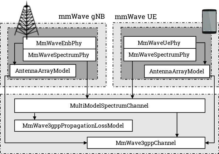
As already mentioned, in this work we extend the ns-3 framework in [9] by incorporating the possibility to simulate the realistic antenna patterns and configurations described in the previous section. As shown in Fig. 2, the channel model implementation in the ns-3 mmWave module depends on a number of classes, with different functionalities. The propagation loss is computed by the MmWave3gppPropagationLossModel class, which implements also a probabilistic model for the LOS and NLOS condition according to [11]. The MmWave3gppChannel, instead, computes the channel matrix for each single transmitter-receiver pair, and applies the beamforming vectors to get the beamformed received power spectral density. Moreover, the AntennaArrayModel class models the antenna arrays at the gNB and the UE. Finally, in each terminal an instance of the MmWaveSpectrumPhy handles the interaction between the PHY layer implementation, the error model and the channel abstraction.
In order to implement the 3GPP antenna array model, the AntennaArrayModel class has been extended to properly handle the presence of multiple antenna arrays, allowing each terminal to transmit and receive with the proper sector (or panel) according to the angular direction of the other transceiver in the link. In the same class, we introduce the possibility of modeling accurate antenna radiation patterns, providing the field patterns to the MmWave3gppChannel, which applies them to the channel matrix. In this first version, we consider the LOS direction to compute the beamforming vector pair for the link. Future extensions will include the possibility of performing a codebook-based beamforming, with a realistic cell scan.
We highlight that all the introduced antenna settings are tunable using the ns-3 attributes system, therefore the framework can be adjusted to simulate 3GPP NR specifications (i.e., with the settings in Tab. I), but also other configurations, resulting in a useful tool for the evaluation of realistic end-to-end mmWave networks.
III Performance Evaluation
III-A Scenario
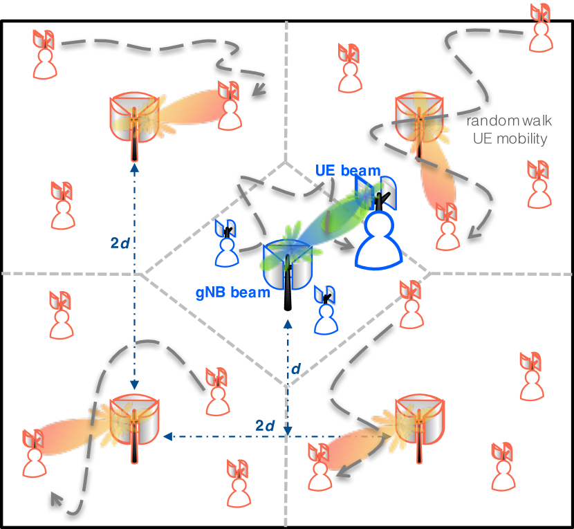
In this paper, we study the performance in terms of end-to-end user throughput and latency in a multi-site deployment, using UDP as the transport protocol. We consider the scenario in Fig. 1, with 4 gNBs at the vertices of a square and a gNB at the center. We consider the distance as a parameter, which can vary in m, a typical range for an ultra-dense mmWave small cell deployment. In this setup, the 5G network is deployed in a Non Stand Alone (NSA) mode, i.e., it uses a 4G Evolved Packet Core (EPC) network, and the UEs are configured with multi-connectivity between an LTE evolved Node Base (eNB) (co-deployed with the central gNB) and an NR gNB [6]. The end-to-end flows are configured as split bearers, i.e., the LTE eNB acts as a local traffic anchor with respect to the core network, and data packets are forwarded to and from the mmWave gNBs, according to the configuration described in [18, 19]. All the base stations are interconnected with X2 links, which are realistically simulated in terms of data rate limit and additional latency, as shown by the parameters in Tab. II.
There are 25 or 50 users in the scenario, and they move randomly according to a two-dimensional random walk model. They can freely hand over between the different mmWave gNBs, or switch to the LTE eNB if all the mmWave links are in the outage condition (i.e., with an SINR below dB). The handover procedure is coordinated by the central LTE unit, and avoids latency-consuming interactions with the core network, as described in [19]. The users consume content from a remote server (e.g., for video streaming), with a constant bitrate Mbit/s.
| Parameter | Value |
|---|---|
| mmWave carrier frequency | 28 GHz |
| mmWave bandwidth | 1 GHz |
| 3GPP Channel Scenario | Urban Micro, Urban Macro |
| mmWave outage threshold | dB |
| mmWave max PHY rate | 3.2 Gbit/s |
| X2 link latency | 1 ms |
| S1 link latency | 10 ms |
| RLC buffer size | 5 MB |
| RLC AM reordering timer | 1 ms |
| S1-MME link latency | 10 ms |
| UE speed | m/s |
| UDP source rate | 100 Mbit/s |
We test a different number of sectors for each mmWave gNB, ranging from 3 to 4. In this first evaluation, we do not consider the single-sector setup with isotropic antenna elements that is still available in the ns-3 mmWave module, since it would be less realistic. The antenna directivity in our simulations is configured as described in Sec. II. The UEs are equipped with 2 panels [17]. We also compare the results for two different 3GPP channel model configurations, namely the Urban Macro (UMa) and the Urban Micro (UMi) scenarios. The channel condition between each user and each gNB is randomly assigned according to the 3GPP model [11].
The metrics we consider are the end-to-end throughput, measured above the transport layer for each user, and the latency in the Radio Access Network (RAN). In particular, in our simulation setup, the end-to-end latency is given by a fixed component in the wired part of the connection, and by a variable one in the RAN (i.e., the PDCP layer latency), which depends on the different configurations we examine. Therefore, in the following sections we will only report the PDCP layer latency.
III-B Impact of the multi-sector deployment
Figs. 3 and 4 show the average UDP end-to-end throughput and RAN latency, respectively, for different numbers of sectors at the gNBs, numbers of users and distances . The number of panels in each UE is fixed to 2.
The first notable result, which holds for both UMa and UMi scenarios, is that the throughput increases when increasing the number of sectors in each gNB from 3 to 4, while the average latency decreases. This is due to a combination of two factors. First, with more sectors it is possible to limit the angular coverage area of each sector, thus beams with a better shape and a higher gain are selected. Second, the interference decreases, since the usage of a multi-sector deployment limits the back and side lobes that generate undesired interference. The end result is an increase in the SINR, which translates into higher throughput and lower latency, given that fewer retransmissions are needed and less buffering occurs. Notice that, on average, the throughput gain is less remarkable than the latency reduction. This is due to the fact that the source rate is limited to Mbit/s, and most of the users experience an average good channel condition and can reach this throughput. The improvement is more relevant for the worst users, i.e., those who generally need a larger number of retransmissions, as we will show in the next paragraphs. Finally, we highlight that increasing the number of sectors has a cost related to the gNB hardware.
The second observation is that the UMi channel condition yields higher throughput and lower latency than UMa. The latter, indeed, generates a larger amount of interference across neighboring cells, thus decreasing the SINR. The UMi scenario, instead, models a street canyon deployment, thus the inter-cell interference is much more limited.
III-C Impact of multiple panels at the UEs
We have shown in the previous result how the multi-sector gNB deployment improves the link budget performance thanks to the possibility to better control the design of both desired and undesired beams. In this section, we consider different values for the number of panels at the UE. As reported in Tab. I, the 3GPP suggests the use of 2 panels for each UE. However, given the importance of handset design in 5G mmWave networks [20, 21], we evaluate the end-to-end performance by also configuring two different numbers of panels (i.e., 2 or 3) at the UE. The results are reported in Fig. 5(a).
Similar to the multi-sector deployment, the performance improves when installing 3 instead of 2 panels at the UEs, for the throughput but more remarkably for the latency. In particular, for the UMi configuration with 3 panels and 4 sectors, it is possible to nearly reach (on average) the maximum throughput without increasing the latency, which has the smallest value with this configuration (i.e., 20.83 ms).
Furthermore, as mentioned in the previous section, the performance improvement can mostly be seen for the worst UEs. Therefore, in Fig. 5(b) we report the Cumulative Distribution Function (CDF) of the throughput for the configuration with 2 or 3 panels at the UE and varying the number of gNB sectors, for the UMa 3GPP channel configuration. The plot shows that, indeed, almost 70% of the users reach the saturation point (i.e., maximum achievable throughput). Moreover, when comparing 2 or 3 panels at the UEs, i.e., the dashed and the solid lines (of the same color), it can be seen that there is an improvement of up to 16 Mbit/s for the 10th percentile. In addition, the gain given by the larger number of panels is generally higher than that given by increasing the number of sectors.
However, even if the use of 3 panels at the UE node results in an improvement of the performance, from a practical implementation point of view, the design of a UE with these many panels must be studied carefully, since it may not be easy to physically place all the panels in the handset. Some preliminary designs and considerations are given in [20, 21].
III-D Comparison with the isotropic antenna array
In the plot of Fig. 6 we compare the average user throughput and latency for the scenario with a multi-sector, multi-panel 3GPP configuration against that with a single sector isotropic antenna elements. In the first, the beamforming vectors are computed as described in Sec. II, while the latter uses the optimal beamformers given by the eigenvector of the largest eigenvalue of the channel matrix [12, 22]. This last approach, which we consider as baseline, represents the default setting for antenna radiation and beamforming in the ns-3 mmWave module.
This comparison highlights the gap in the performance between the two antenna array models considered. The throughput is slightly lower (and, conversely, latency is higher) in the 3GPP antenna array model for both UMi and UMa scenarios. This is due to the use of the optimal beamforming vectors together with the isotropic antenna model which result in a configuration that identifies an upper bound in the performance. Indeed, even if the interference power irradiated in the side lobes of the isotropic antenna array model is bigger than in the 3GPP model, this cannot balance the advantage of the optimal beamforming vectors. A detailed evaluation on the effects of the interference power irradiated can be found in [16, 23].
IV Conclusions
In this paper, we improved the channel model abstraction of the mmWave module for ns-3, by introducing the support of a more realistic antenna array model, compliant with 3GPP NR requirements, which adopts multiple antenna arrays at the base stations and mobile handsets. We then evaluated the end-to-end performance of a mmWave cellular network by varying channel and antenna array configurations. Our results show that by increasing the number of sectors it is possible to improve the SINR, thus increasing user throughput and at the same time decreasing latency. Moreover, we highlight that the configuration with a single sector of isotropic antenna elements and optimal beamforming vectors has results which are slightly better than the configuration with 3GPP specifications in the scenario we consider, i.e., with a limited number of interfering sources.
Therefore, as a future extension of this work, we will further evaluate the end-to-end performance of networks with different multi-sector and multi-panel configurations, to clearly outline the trade-offs related to the antenna array configurations and their modeling. For example, we will analyze larger simulation scenarios, i.e., with more gNBs and UEs deployed and consequently a higher interference, other antenna array factor components, such as the spacing of the elements and the amplitude and the phase vectors of each antenna element, and network configurations.
References
- [1] Cisco, “Cisco Visual Networking Index: Global Mobile Data Traffic Forecast Update, 2016–2021,” White Paper, March 2017.
- [2] S. Rangan, T. S. Rappaport, and E. Erkip, “Millimeter-Wave Cellular Wireless Networks: Potentials and Challenges,” Proceedings of the IEEE, vol. 102, no. 3, pp. 366–385, March 2014.
- [3] 3GPP, “NR and NG-RAN Overall Description - Rel. 15,” TS 38.300, 2018.
- [4] 3GPP, “NR - Physical channels and modulation - Release 15,” TR 38.211, 2017.
- [5] J. S. Lu, D. Steinbach, P. Cabrol, and P. Pietraski, “Modeling human blockers in millimeter wave radio links,” ZTE Communications, vol. 10, no. 4, pp. 23–28, 2012.
- [6] 3GPP, “Evolved Universal Terrestrial Radio Access (E-UTRA) and NR; Multi-connectivity,” TS 37.340 (Rel. 15), 2018.
- [7] M. Pieska and A. Kassler, “TCP performance over 5G mmWave links - Tradeoff between capacity and latency,” in IEEE 13th International Conference on Wireless and Mobile Computing, Networking and Communications (WiMob), Oct 2017, pp. 385–394.
- [8] M. Polese, R. Jana, and M. Zorzi, “TCP in 5G mmWave networks: Link level retransmissions and MP-TCP,” in IEEE Conference on Computer Communications (INFOCOM) Workshops, May 2017, pp. 343–348.
- [9] M. Mezzavilla, M. Zhang, M. Polese, R. Ford, S. Dutta, S. Rangan, and M. Zorzi, “End-to-End Simulation of 5G mmWave Networks,” IEEE Communication Surveys & Tutorials, 2018. [Online]. Available: https://arxiv.org/abs/1705.02882
- [10] T. R. Henderson, M. Lacage, G. F. Riley, C. Dowell, and J. Kopena, “Network simulations with the ns-3 simulator,” SIGCOMM demonstration, vol. 14, no. 14, p. 527, 2008.
- [11] 3GPP TR 38.900 v14.2.0, “Technical Specification Group Radio Access Network; Study on channel model for frequency spectrum above 6 GHz,” Tech. Rep., 2016.
- [12] M. Zhang, M. Polese, M. Mezzavilla, S. Rangan, and M. Zorzi, “Ns-3 Implementation of the 3GPP MIMO Channel Model for Frequency Spectrum Above 6 GHz,” in Proceedings of the Workshop on Ns-3, ser. WNS3 ’17, 2017, pp. 71–78.
- [13] C. A. Balanis, Antenna Theory: Analysis and Design. Wiley-Interscience, 2005.
- [14] 3GPP TR 37.840 v12.1.0, “Technical Specification Group Radio Access Network; Study of Radio Frequency (RF) and Electromagnetic Compatibility (EMC) requirements for Active Antenna Array System (AAS) base station,” Tech. Rep., 2013.
- [15] 3GPP TR 36.873 v12.4.0, “Technical Specification Group Radio Access Network; Study on 3D channel model for LTE,” Tech. Rep., 2017.
- [16] M. Rebato, L. Resteghini, C. Mazzucco, and M. Zorzi, “Study of realistic antenna patterns in 5G mmwave cellular scenarios,” in IEEE ICC 2018 Communications QoS, Reliability, and Modeling Symposium (ICC’18 CQRM), Kansas City, USA, May 2018.
- [17] 3GPP, “Study on New Radio (NR) Access Technology - Physical Layer Aspects - Release 14,” TR 38.802, 2017.
- [18] M. Polese, M. Mezzavilla, and M. Zorzi, “Performance Comparison of Dual Connectivity and Hard Handover for LTE-5G Tight Integration,” in Proceedings of the 9th EAI International Conference on Simulation Tools and Techniques (SIMUTOOLS), 2016, pp. 118–123.
- [19] M. Polese, M. Giordani, M. Mezzavilla, S. Rangan, and M. Zorzi, “Improved Handover Through Dual Connectivity in 5G mmWave Mobile Networks,” IEEE Journal on Selected Areas in Communications, vol. 35, no. 9, pp. 2069–2084, Sept 2017.
- [20] Y. Huo, X. Dong, and W. Xu, “5G Cellular User Equipment: From Theory to Practical Hardware Design,” IEEE Access, vol. 5, pp. 13 992–14 010, July 2017.
- [21] Y. Huo, X. Dong, W. Xu, and M. Yuen, “Cellular and WiFi Co-design for 5G User Equipment,” ArXiv e-prints, March 2018. [Online]. Available: https://arxiv.org/abs/1803.06943
- [22] D. J. Love and R. W. Heath, “Equal Gain Transmission in Multiple-input Multiple-output Wireless Systems,” IEEE Transactions on Communications, vol. 51, no. 7, pp. 1102–1110, July 2003.
- [23] M. Rebato, M. Mezzavilla, S. Rangan, F. Boccardi, and M. Zorzi, “Understanding Noise and Interference Regimes in 5G Millimeter-Wave Cellular Networks,” in 22th European Wireless Conference, 2016.